Transcription
Youth Explore Trades SkillsDesign and Drafting – 3D Modelling (Architectural CAD)Symbols and Standards (Architectural CAD)DescriptionIn this activity the teacher will give an orientation to the symbols and conventions of ArchitecturalCAD. Industry common symbols are used for most of the fixtures and hardware that go into anybuilding, and these can be either drawn by the designer or accessed through the Internet.Lesson ObjectivesThe student will be able to: Define blocks Explain what standards are Draw their own symbols Copy the symbols and place them in a drawing with correct orientation Use the stretch command to pull windows to the correct size Save the block as a drawing for insertion into the building drawing in Activity 12: Drawingof a Simple Building (Architectural CAD)AssumptionsThe student will: Know how to login to a computer and open up the software Know how to save the drawing as a named file in their own directory Have been introduced to the basic commands for drawing 2D objectsTerminologyBlock: a predefined architectural object that is made or found within a library on the computer, onthe network or the Internet. Blocks are available for all aspects of design regardless of specialtyof the designer.Scale: a drawing that is enlarged or reduced from its original size, usually expressed as a fractionin imperial measurement. The most common architect’s scale is ¼ inch to the foot, expressedas Scale ¼" 1'-0". In metric measurement, scale is expressed as a ratio (e.g., 1:50, meaning 1mm in the drawing equates to 50 mm in the actual work). The actual building measure would bemultiplied by the scale factor.Standard: an industry-agreed use of units (whether imperial or metric), drawing layout, layerconventions, line types, dimensioning, and plot styles.This work is licensed under a Creative Commons Attribution-NonCommercial-ShareAlike 4.0 International License unless otherwise indicated.
Symbols and Standards (Architectural CAD)Design and Drafting – 3D ModellingStandards: industry-agreed ways and means for the use of designers to have a commonlanguage for common objects and rules used in all drawings.Stretch command: used to pull objects from the length they are drawn to a desired length,longer or shorter. For example, if a wall in the drawing of a building must be stretched to make it2' longer, the portions of the wall that need to be stretched are picked, a base point (usually anintersection on the wall) is picked, and then using polar linear directional command (e.g., @2' 0),the wall can be lengthened this precise amount.Trim: where lines, circles, and all other linear objects intersect and cross over each other ina manner that is not desired, the excess portion of the lines can be trimmed using the Trimcommand.Estimated Time60 minutesRecommended Number of Students20, based on BC Technology Educators’ Best Practice GuideFacilitiesComputer lab installed with CAD software (Google SketchUp, AutoCAD, Cadopia, Vector works,etc.) and Internet accessToolsProjector with computer and speakers installed with CAD softwareMaterialsStudent activity handout with instructionsResourcesInstructional video for teacher and students to follow: 11.1: Changing Your Model Space 11.2: Drawing Architectural Blocks for a BuildingAbout Unit Conventions—Autodesk AutoCADExplanation of some of the conventions for 7B5-1806FAAC12B2-htm.htmlArchitectural SymbolsA good example of a simple set of ols.pdf with permission from:David Mussaw, Cerrito College, California.2Youth Explore Trades Skills
Design and Drafting – 3D ModellingSymbols and Standards (Architectural CAD)Teacher-led ActivityThe intent of the teacher-led activity is to demonstrate the setting up of the model space in thecorrect architectural format to ensure the blocks are drawn to the scale of the drawing. Thefollowing should be demonstrated: Projecting the completed drawing (Figure 1) Mouse movement (scroll in/out, right/left buttons, pan) Command line: inputting commands (zoom, limits, grid, etc.) Coordinate entry and the line command (absolute, relative, polar) Use of a pick window (right click and hold). If the pick window is green (in AutoCAD 16),multiple objects can be selected by just touching them with the window. If the pick windowis blue, the objects must be wholly inside the window.Student ActivityStudents will follow the student activity and draw their own set of blocks, then save that drawingfor insertion into the small shed drawing in the Drawing of a Simple Building (Architectural CAD)activity. This will be done after the small shed file has been started and the drawing has beenset up with the correct units, limits, Dimstyle, grid, and snap.AssessmentAssessment will be on a “done or not done” basis. The student must have completed all thesymbols required: Door symbol Light fixture Outlet fixture WindowThe file must be saved and/or printed with the student’s name inserted in the drawing using thetext tool.Important NoteIt is easily possible for students to copy each other’s work and resave the file under their owndrive and file name. It is important that students save the block drawing with their first nameincluded in the file name.If the teacher suspects that a student has copied the drawing file from another student, followthe procedure below. This applies for all recent versions of AutoCAD. Have the suspected student open their file, if it is not already open. Type the word time. The drawing editing time will be displayed. If the time is mere minutes or less than an observed time of other students, then theteacher would have evidence of cheating/copying. The student would then have to start thedrawing again from scratch or take a zero mark on the activity.Youth Explore Trades Skills3
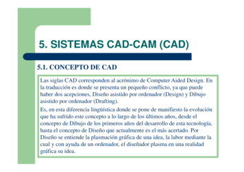
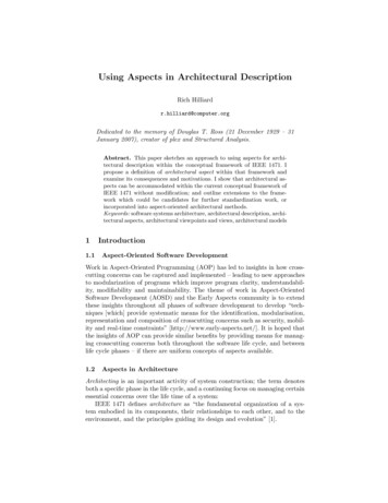
Symbols and Standards (Architectural CAD)Design and Drafting – 3D ModellingStudent ActivityUsing the software, create the drawing and produce your own architectural blocks using thedrawing set-up and the commands that have been demonstrated to you. In this activity and inthe small shed drawing in the Drawing of a Simple Building (Architectural CAD) activity, all unitswill be done using imperial measurement. The settings for the drawing will be architectural in theunits dialog box and the dimstyle dialog box.Your assignment is to draw all of the drafting symbols found in Figure 1 below (you do not needto draw the labelled leaders).Figure 11. Switch symbol. A switch symbol is just the letter S inserted as a text object. The height ofthe text should be 4". Type TEXT. Follow the prompts by pressing Enter for each one untilyou get the prompt to click on the location where you want the S to be placed. Three- andfour-way switches are noted with superscripts, for example S3 and S4 in AutoCAD 16 or bytyping the number S3 or S4 in the same text entry box in other versions of AutoCAD or othersoftware packages.2. Door symbol. The door symbol is made with a 36" vertical line. The arc of the door is madeby using the circle command. The centre of the circle is started at the bottom end of theline with a radius of 36". A line must be added to trim out three-quarters of the circle. This isdone by drawing a line starting at the bottom end of your first line and drawing it horizontallythrough the circle any distance. Type TRIM, press Enter, select the lines and the circle,and press Enter. Then pick the parts of the circle you want to trim out and delete the extraline. Two vertical lines 6" long should be added to the end of the arc and the base of thedoor to represent the thickness of standard walls as they are in all new frame construction(Figure 2).4Youth Explore Trades Skills
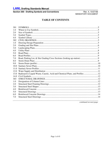
Design and Drafting – 3D ModellingSymbols and Standards (Architectural CAD)Figure 2—Lines from the door symbol extend to represent the thickness of the wall3. Light fixture symbol. A light fixture symbol is just a 4" circle with line parts at the north andsouth ends of the circle. This is done by drawing two vertical lines starting at the centre ofthe circle for a distance of about an inch outside the circle. Copy the whole object and placeit away from your light fixture, as you will be using it to make your outlet symbol. The interiorof the lines can be trimmed out using the Trim command.4. Outlet symbol. With the copy of the light fixture, use the Offset command to offset thecentre lines of the light fixture 1" on either side of the centre line. Type OFFSET, pick the twolines in the centre of the circle (it looks like one but you know there are two), press Enter,then enter the distance of 1" (be sure to put in the quotation mark). Press Enter, then pickon each side of the original line and there will be the two lines for the outlet. Delete the extracentre line (Figure 3).Figure 3—Steps involved in creating the outlet symbol5. Window symbol. This is the simplest style for drawing windows, though there are others.Draw a 6" horizontal line. Offset this line the length you want the window to be, using theOffset command; enter the distance in feet or inches. To draw the centre line of the windowbetween the offset lines you have just drawn, type L for line, type MID for the middle of theline, pick the middle of one of your lines, and then type MID again and pick the midpoint ofthe other line.Youth Explore Trades Skills5
Symbols and Standards (Architectural CAD)Design and Drafting – 3D Modelling6. To stretch the window either longer or shorter, type STRETCH and make a pick windowaround one end of the window; be sure to pick the endpiece and a bit of the centre line ofthe window. Press Enter after the selection and pick the intersection of the centre line andthe end of the window. Press Enter and pull the pieces in the direction and in the amountyou want to go. Then let the mouse drop the end of the window at the desired length.7. Save the drawing as myblocks.dwg.Commands to Use/LearnCentre rint / PlotSnapTextTrimMidpointUnitsMoveZoomYouth Explore Trades Skills
Design and Drafting – 3D ModellingSymbols and Standards (Architectural CAD)Procedure1. Open up a new file in your CAD software.2. Set units to “Architectural” (Figure 2). As in the included images at the end of the activity.3. Set your Grid to 2" and your Snap to 6".4. Limits: set up 0,0,0 and upper right corner 32',24'5. Units (Figure 4), Print / Plot (Figure 5), and Dimstyle (Figure 6) MUST be set to the values inthe screen captures. Look at the figures and set them carefully in AutoCAD. All other defaultsettings are satisfactory, though they can be changed if required.Units WindowSet “Type” to “Architectural” (Figure 4).Figure 4Youth Explore Trades Skills7
Symbols and Standards (Architectural CAD)Design and Drafting – 3D ModellingPrint/Plot WindowUse the print/plot window when you want to print your drawing. In this case, the plot is setto save to a PDF file. Otherwise, you can print to your local or network printer by selecting itin the “Printer/plotter” name list. Do not forget to set the orientation to “Landscape” and the“What to plot:” to “Limits” to plot to a standard letter-size paper (Figure 5).Figure 58Youth Explore Trades Skills
Design and Drafting – 3D ModellingSymbols and Standards (Architectural CAD)Dimstyle WindowSet “Unit format” to Architectural in the Primary Units tab (Figure 6). Also go to the Fit taband change the “Use overall scale of” to 32 to reflect the fact you have scaled up your limitsto 32' by 24' from the 11" by 8.5" used in the Draw Your Border activity.Figure 66. When you are finished, save the file. You will be able to open this file later for otherassignments to use the symbols. To save, select “Save As” from either the Application Menuor the Quick Access toolbar in the upper-left corner of the program (Figure 7). When the“Save Drawing As” window opens up, navigate to the folder where you save your work. Saveyour work as “myblocks.dwg” as shown (Figure 8).Youth Explore Trades Skills9
Symbols and Standards (Architectural CAD)Design and Drafting – 3D ModellingFigure 7Figure 810Youth Explore Trades Skills
Draw their own symbols Copy the symbols and place them in a drawing with correct orientation Use the stretch command to pull windows to the correct size Save the block as a drawing for insertion into the building drawing in Activity 12: Drawing of a Simple Building (Architectural CAD) Assumptions The student will: