Transcription
LANL Drafting Standards ManualSection 300 - Drafting Symbols and ConventionsRev. 4, 10/27/06MANDATORY DOCUMENTTABLE OF BOLS .5Where to Use Symbols .5Size of Symbols .5Symbol Types.5Symbol Library .5CIVIL DRAWINGS .5Drawing Design Preparation .5Grading and Site Plans .6Landscaping Plans.7Utility Plans .8Road Plans .8Road Profiles .9Road, Parking Lot, & Site Grading Cross Sections (looking up-station) .9Storm Drain Plans .9Storm Drain (profile) .10Sanitary Sewer Plans .10Sanitary Sewer Profiles .11Water Supply and Distribution .11Radioactive Liquid Waste, Caustic, Acid and Chemical Plans, and Profiles .12Civil Symbols.12STRUCTURAL DRAWINGS .12Designation of Column Lines .12Structural Steel Framing Drawings .12Structural Steel Shapes .13Reinforced Concrete .13Structural Drawings .13Reinforced Concrete Drawings .14Structural Steel Drawings .14continued on next pagePage 1 of 45
LANL Drafting Standards ManualSection 300 - Drafting Symbols and ConventionsRev. 4, 10/27/06MANDATORY DOCUMENTTABLE OF CONTENTS .06.07.03071.02.03.0ARCHITECTURAL DRAWINGS .15Drawing Design Preparation .15Life Safety Plans .15Demolition Plans.16Foundation Plans .16Floor Plans .17Reflected Ceiling Plans .18Floor Finish Plans .19Building Elevations .19Building Sections .20Enlarged Details and Plans .21Roof Plans (Construction).21Floor Plans of Record (FPR).22Roof Plan of Record (RPRs) .29Miscellany .30Evacuation Route Diagram (ERD) .31Architectural Symbols.32MECHANICAL DRAWINGS.32Mechanical Drawings .32Process Flow Diagrams (PFDs) & Piping & Instrument Diagrams (P&IDs) .33Mechanical Equipment List .35Mechanical Symbols .36ELECTRICAL DRAWINGS .36General .36One-Line Diagrams .36Electrical Equipment Plans .37Wiring Diagrams .38Electrical Schematics .38Electrical Schedules .38Lightning Protection System (LPS) .38PLUMBING .39General .39Plumbing Systems .39Isometrics and Schematics .39continued on next pagePage 2 of 45
LANL Drafting Standards ManualSection 300 - Drafting Symbols and ConventionsRev. 4, 10/27/06MANDATORY DOCUMENTTABLE OF CONTENTS (continued)308 FIRE PROTECTION DRAWINGS .401.0 Drawing Design Preparation .402.0 Building Architectural and Structural Features.413.0 Emergency Lighting .414.0 Fire Alarm Systems .425.0 Special Extinguishing Systems .426.0 Sprinkler Systems .437.0 Water Supplies .448.0 Other Systems .449.0 Attachments .45Attachment 1: Historically Used Drawing Numbers .45Attachment 2: Existing Facility Modification Process Guidance .4510.0 Appendices .45Appendix A: General – Plot Limits, Txt Conversions, Line Types Chart .45Appendix B: General Symbols Chart.45Appendix C: Civil Symbols Chart .45Appendix D 1-3: Fire Protection Symbols Chart .45Appendix E 1-3: Mechanical Symbols Chart .45Appendix F 1-3: Electrical Symbols Chart .45Appendix G 1-4: P&ID and PFD Symbols Chart .45Appendix H: Title Blocks and Title Sheet Informational Chart .45Appendix I: Architectural Symbols Chart.45Appendix J: Plumbing Symbols Chart .45Appendix K: Welding Symbols Chart .45Page 3 of 45
LANL Drafting Standards ManualSection 300 - Drafting Symbols and ConventionsRev. 4, 10/27/06MANDATORY DOCUMENTRECORDS OF 5/02309/16/043change 109/26/05410/27/06POCDocument rewritten and reformatted to support LIR220-03-01, Facility Engineering Manual. Thischapter supersedes LANL Facility EngineeringStandards Drafting Manual, Vol. 2, Rev. 7, dated4/17/98.Danny Nguyen,Dennis McLain,PM-2FWO-FESymbols - generated & on-line; Civil – expanded;Structural – slight modification; Architectural,Mechanical, Electrical - expanded greatly;Mechanical and Electrical - also refer to LEM newexamples.Richard Trout,Mitch S. Harris,FWO-SEMFWO-SEMAdd new subsections (7.0 & 8.0) on Record FloorPlans. Correct Layering Table. Minor editorialchanges as indicated by revision bars.Richard Trout,Kurt Beckman,FWO-SEMFWO-SEMAdded requirements for evacuation route diagrams,various plans: life safety, demolition, reflectiveceiling, floor and roof plans of record; lightningprotection drawings, plumbing and fire drawings.Addition of Attachment 1. Change from LEM toESM (Engineering Standards Manual). Othereditorial changes as noted by revision bars.Richard Trout,Gurinder Grewal,FWO-DECSFWO-DOMinor change. Corrected grid lines on Fig. 303-1 andorganizational name changes.Richard A. Trout,Gurinder Grewal,ENG-DECSENG-CEAdministrative changes only. Organization andcontract reference updates from LANS transition.IMP and ISD number changes based on new Conductof Engineering IMP 341. Master Spec number/titleupdates. Other administrative changes.Richard Trout,Kirk Christensen,FM&E-DESCENGPLEASE CONTACT THE DRAFTING STANDARDS POCfor upkeep, interpretations, and variance issuesLDSMOICDrafting Manual POCPage 4 of 45
LANL Drafting Standards ManualSection 300 - Drafting Symbols and Conventions301SYMBOLS1.0WHERE TO USE SYMBOLSRev. 4, 10/27/06Use standard symbols on all drawings, whenever possible. Guidance: The use of symbols canreduce the drawing time and clarify the drawings by the elimination of unnecessary details.2.0SIZE OF SYMBOLSGuidance: Symbol sizes can vary according to their use on drawings made “to scale” or “not toscale.” The size of symbols on drawings “not to scale” is dependent upon the complexity andaesthetics of the drawings.3.0SYMBOL TYPESThe LANL Drafting Symbols Library is not intended to be a complete listing of all possiblesymbols required for a project. Symbols may be created if not available in the LANL DraftingSymbols Library or in industry standard symbols. The Library’s symbols can be revised viacontrolled revisions by the Drafting Manual POC with Standards Manager approval and without aManual revision.Identify symbols generated that are not in the LANL Drafting Symbols Library on the disciplinelegend with a (NS) “non standard” located to the right of the symbol description.4.0SYMBOL LIBRARYA. Symbols generated in the LANL symbol library are drawn 1:1. Insert accordingly,consistently, and to the proper size in relation to the drawing.B. Do not explode symbols with text to meet text requirement in Section 213.C. Symbols generated are from various National Standards. When discrepancies in symbolsoccur in the National Standards, only one was selected to be placed in the library.D. Symbols are revised on a regular basis. LANL will only indicate symbol revisions by notatingthe new revision number and date on the affected appendix, not on each individual symbol.302CIVIL DRAWINGS1.0DRAWING DESIGN PREPARATIONA. Draw to scale and show north arrow symbol. Show dimensions including elevations in feetand decimals of a foot.B. Include in the site plan existing planimetric features such as buildings, roads, walks, parkingareas, large trees, underground and overhead utilities, valve boxes, water meters, fire hydrants,pressure reducing valves, backflow preventers, thrust blocks, valve pits, and other featurespertinent to the specific project.Page 5 of 45
LANL Drafting Standards ManualSection 300 - Drafting Symbols and ConventionsRev. 4, 10/27/06C. Refer to the mechanical drawings for lift stations, sumps, valves, etc. Include in the civildrawings site utilities outside building perimeters. Electrical/communications site plans maybe separated from the utilities plans providing they are carefully coordinated.D. Prepare the site plan from a current survey tied to known survey markers located in accordancewith the New Mexico State Plan Coordinate System (NMSPC), central zone, North AmericanDatum 1983 (NAD), and mean sea level elevations. Provide appropriate drawing scale toclearly identify the project construction limits, planimetric features, and proposedimprovements. Provide additional sheets with match lines if necessary. Include in the planinformation necessary for layout of all elements of the new project.E. Include in the plans, or separate drawing, existing and new features including final contoursclearly annotated at appropriate intervals; spot elevations; finish grades for drainage; siteimprovements; plan and profile of roads, walks, and drainage structures; test hole boringlocations; and borehole data (if available).F. Include in the landscape and/or terrain management plan, a list of plant materials, fences,signs, erosion control measures, irrigation systems, berms, screens, gravel areas, lights, andother landscape features, amenities, and structures.G. Provide plan and profile drawing sheets for existing and new utility systems in the areasurrounding the project. Prepare a plan and profile for new underground utility systemsshowing invert elevations, pipe slopes, and cover depths over the systems shown. Providescale of 1 inch equals 20 feet. Adjustments to the scale are allowed to improve clarity or toavoid excessive sheets and match lines.H. Prepare design profiles for: sanitary sewers, storm drains, steam and condensate lines,roadways, drainage channels, and other facilities as required.I.Prepare earthwork cross sections for: roadways, parking lots and site grading.J.Prepare profiles or cross-sections for locations where new underground utility runs cross otherexisting utilities. Show new utility lines as continuous in profile with break lines provided toshow changes in direction. Stationing for gravity sewers, storm drains and drainage channelsshall progress up gradient where possible. Progress stationing from left to right on thedrawing, preferably with the north arrow pointing up or to the right side of the drawing.K. Reproduce the soil boring logs and required notes on the drawings. Show borehole locationsin plan view with accurate state plane coordinates, surface elevations and stratigraphic depthinformation.2.0GRADING AND SITE PLANSInclude the following:A. Existing utilities including type, size, and locations from field survey information.B. Existing permanent structures, roadways, fences, walks, retaining walls, and any additionalplanimetric features to clearly identify the work area.Page 6 of 45
LANL Drafting Standards ManualSection 300 - Drafting Symbols and ConventionsRev. 4, 10/27/06C. Manhole invert and rim elevations for existing sewers, storm drains, electrical manholes, andall other manhole types.D. New construction, items to be removed, and limits of work. Provide a site removal plan ifappropriate.E. Clearing and grubbing areas.F. Existing contours, finished contours, and critical (existing and finish) spot elevations forproposed grading and paving improvements.G. Stationing, NMSPC coordinates or bearings and distances for location of facilities.H. Boring test holes and logs where applicable.I.Cross sections where major grading work is involved.J.Storm Water Pollution Prevention Plan (SWPPP) with proposed erosion control measures.K. Match lines of adjacent drawings.L. Fencing (standard or security).M. Pedestrian/vehicle circulation patterns, curb and gutter, parking layout, striping, permanentsigning, and sidewalks.N. Location map.O. Traffic control plan including temporary construction signing and signals in accordance withthe Manual of Uniform Traffic Control Devices.P. Stockpile and borrow areas.Q. Temporary laydown areas for the contractor’s equipment.R. Security fence locations for “Bubbled Out” (space left blank for security purposes) areas.3.0LANDSCAPING PLANSInclude the following:A. Planting/irrigation.B. Recreational layouts.C. Visual screening.D. Plant species and size.Page 7 of 45
LANL Drafting Standards ManualSection 300 - Drafting Symbols and Conventions4.0Rev. 4, 10/27/06UTILITY PLANSInclude the following:A. Location of existing structures and facilities (no contours required).B. Location of all utilities and describe them as to size, type material, slope and indicate fittings.C. Proposed points of intersections of all utilities crossings for interference.D. Depth of cover for utilities.E. Details.F. Rim and invert elevations on sanitary sewer and storm drainage.5.0ROAD PLANSInclude the following:A. Geometric plan and profile, pavement markings, surfacing, thickness, cross section, and trafficcontrol devices.B. Operational plan for vehicular circulation is required showing turnaround movements, ingressand egress.C. Centerline location, coordinates, or bearing and distances.D. Stationing.E. Curve data (show delta (D), radius (R), tangent (T), length (L), chord bearing (CH), point ofcurvature (PC), point of intersections (PI), and point of tangency (PT).F. PC and PT stationing.G. PI coordinates.H. Typical roadway sections with pavement type and thickness, base and sub-grade materials,cross slopes, and taper details.I.Drainage culverts, size and type, ditches, and hillside interceptor benches and slopes. Includeflowline elevations at culverts and slopes.J.Utility crossings.K. Horizontal alignment design parameters.Page 8 of 45
LANL Drafting Standards ManualSection 300 - Drafting Symbols and Conventions6.0Rev. 4, 10/27/06ROAD PROFILESInclude the following:A. Ground line (existing grade at centerline road).B. Finished grade (top of finished surface at centerline).C. Left and right curb profiles (if required).D. Longitudinal grades in percentages.E. Elevations at station intervals and vertical curves including: vertical point of curvature (VPC),vertical point of intersection (VPI), and vertical point of tangency (VPT).F. Elevations along vertical curve and tangents (if required).G. Vertical alignment design parameters.H. Drainage culverts & utility crossings.7.0ROAD, PARKING LOT, & SITE GRADING CROSS SECTIONS (LOOKING UP-STATION)Include the following:A. Stationing, scales, and earthwork requirements.B. Centerline and/or baseline location.C. Existing ground line (phantom line type).D. Finished grade surface and bottom of base course (continuous linetype).E. Annotate cut and fill slopes.F. Ditch sections and structural features such as drop inlets, culverts, etc.8.0STORM DRAIN PLANSInclude the following:A. Existing underground structures including size, type, and location. (To be relocated orremoved.)B. Existing storm drains, culverts, inlets, and outfall structures.C. Existing utilities.D. New storm drain location (including coordinates, distances, and bearings), stationing, curvedata (show D, R, T, L, PC, PI and PT), manholes, transitions, and junction structures.Page 9 of 45
LANL Drafting Standards ManualSection 300 - Drafting Symbols and ConventionsRev. 4, 10/27/06E. Catch basin locations. (Tie to curb returns or centerline road stationing/offset), type, size,invert elevations).F. Pipe length, size, type, pipe slope, and end inverts.G. Utilities crossings - water, sewer, gas, steam, electric, telephone, etc.H. Unique trenching, shoring, benching, and/or backfill requirements.9.0STORM DRAIN (PROFILE)Include the following:A. Ground line (existing grade at centerline storm drain).B. Street names, building designations, and existing structures.C. Existing underground utilities including sizes, types, interferences, and elevations.D. Centerline stationing, match lines, manholes, structures, design slopes, flow rates, and gradechanges.E. Storm drain slope (ft/ft), invert elevations, length, size, type of pipe, centerline stationing,direction of connecting pipe inlets, and transition structures.F. Parallel existing storm drains.G. Parallel existing utilities.H. Concrete or other encasement for utility crossings.I.Details of crossings with existing utilities.10.0 SANITARY SEWER PLANSInclude the following:A. Existing underground utilities, size, type, and location.B. Proposed sewer centerline geometry (coordinates, distances, and bearings), stationing, curvedata (show D, R, T, L, PL, PI and PT), manholes (type and all callouts from standarddrawings), and sizes.C. Encasement of sewer.D. Curbs, driveways, and sidewalks to be removed and replaced.E. Fire hydrants, valves, meters or other utility appurtenances to be relocated.Page 10 of 45
LANL Drafting Standards ManualSection 300 - Drafting Symbols and ConventionsRev. 4, 10/27/0611.0 SANITARY SEWER PROFILESInclude the following:A. Existing ground line and proposed cover along center line of sewer.B. Substructures and/or utilities (parallel or crossing) including size, type, rim and invertelevations (excavated and checked, if required).C. Centerline stationing, match lines, manholes, structures, design slopes, flow capacity, andgrade changes.D. Sewer profile slope and elevations, (ft/ft) and (ft), length, type, and diameter of pipe,centerline stationing, and direction of connecting inlets or Y branches.E. Parallel existing storm drains.F. Encasement for sewers.G. Details of crossings with existing utilities.12.0 WATER SUPPLY AND DISTRIBUTIONInclude the following:A. Location of all structures and facilities.B. Location, size and type of domestic water lines, valves, valve pits, meters, etc.C. Location, size and type of fire water lines, hydrants, post indicator valves, PRV’s, storagetanks, valves, valve boxes, meters, and pits.D. Coordinates at all angle points of distribution lines.E. Bearing and distance between PI's.F. Show existing utilities and structures along alignment.G. Show section cut including invert elevations at all utility crossings.H. Horizontal/vertical alignment design parameters.I.Typical trench sections, bedding, and backfill requirements.J.Restrained fittings and/or thrust block locations and calculations.K. Horizontal geometry including curve data, if required, D, R, T, L, PC, PI and PT.Page 11 of 45
LANL Drafting Standards ManualSection 300 - Drafting Symbols and ConventionsRev. 4, 10/27/0613.0 RADIOACTIVE LIQUID WASTE, CAUSTIC, ACID AND CHEMICAL PLANS, ANDPROFILESInclude the following:A. Existing ground line and proposed cover over the piping.B. Substructures and/or utilities (parallel or crossing) including size, type, rim and invertelevations (excavated and checked, if required).C. Piping profile slope and elevations, (ft/ft) and (ft), length and type of pipe, size, station size,and direction of connecting inlets or Y branches.D. Monitoring system instrument and controlE. Location of control valves, type, model number, and access requirements.F. Centerline stationing, match lines, manholes, structures, design slopes, flow capacity, andgrade changes.G. Encasement for piping.H. Details of crossings with existing utilities.14.0 CIVIL SYMBOLSSee Appendix C of this manual.303STRUCTURAL DRAWINGS1.0DESIGNATION OF COLUMN LINESOn the Plot Plan and Foundation Drawings, locate structures by coordinates or orthogonal offsets.The location of the base point coordinate shall be the intersection of the column lines in thenortheast corner of the structure, where practical. The column line bearing and offset distance, orcoordinate of an alternate column line intersection point shall be designated, see section 201.5.2.0STRUCTURAL STEEL FRAMING DRAWINGSFraming Plans and Framing Elevations are schematic drawings. Show the centerlines of steelframing members as solid heavy lines stopping short of the member they frame into. Only showpartial outlines of webs, flanges, and legs of members when necessary for clarity.Page 12 of 45
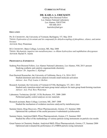
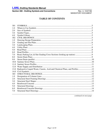
LANL Drafting Standards ManualSection 300 - Drafting Symbols and ConventionsRev. 4, 10/27/06Example:Figure 303-13.0STRUCTURAL STEEL SHAPESLabel structural steel construction, per AISC M013, “Detailing for Steel Construction."4.0REINFORCED CONCRETESymbols commonly used on reinforced concrete drawings are:#To indicate size of deformed bar (superscript)ØPlain rounds, e.g., spirals (superscript)@Spacing center to centerDirection in which bars extendLimits of area covered by bars5.0STRUCTURAL DRAWINGS5.1DimensioningOn plan views, dimensions are to be tied into points that can readily be transferred to concrete,steel, and other drawings including plot plans. Clearly indicate match lines and centerlines ofcolumns and equipment. When possible, keep dimensions outside the equipment and details.Dimension drawings in feet and inches.Page 13 of 45
LANL Drafting Standards ManualSection 300 - Drafting Symbols and Conventions5.2Rev. 4, 10/27/06ElevationsA. Indicate elevations in decimals of a foot, e.g., EL 96.25. Indicate elevations on SuperstructureConcrete and Steel Drawings in feet and inches, e.g., EL 115' - 6-1/2"B. Indicate floor and platform elevations to top of steel. Reference floor plate, top of grating ortop of slab as or - elevation to top of steel.C. Generally, the high point of the ground floor slab is to be the main vertical reference line.5.3CoordinatesOn the Floor Plan and Foundation Drawing, locate structures by 2 sets of coordinates. Thelocation of the coordinates shall be the intersection of the column lines and/or at corners of thestructure, where practical.5.4Loads and ReactionsA. Indicate the design loads for principal equipment supported on the drawings in their respectivelocations or in table format.B. Note Foundation Drawings with “Max Foundation Bearing Capacity lbs/sq. ft.”Piling Drawings shall be noted with "Max Pile End Bearing Pressure lbs/sq.ft.”C. Show floor and roof live loadin
A. Symbols generated in the LANL symbol library are drawn 1:1. Insert accordingly, consistently, and to the proper size in relation to the drawing. B. Do not explode symbols with text to meet text requirement in Section 213. C. Symbols generated are from various National Standards. When discrepancies in symbols