Transcription
Tevatron BPM Hardware h 30, 2004Electronic Design DocumentVince Pavlicek, Mark Bowden, Bill Haynes, Ken Treptow,Margaret Votava, Fermilab - Computing Division - CEPABob Webber, Fermilab - Accelerator Division - Accelerator ControlsDepartmentJim Steimel, Fermilab - Accelerator Division - Tevatron DepartmentAbstractThis document contains the specification for the Beam Position Monitor (BPM) upgradedata acquisition hardware. Expected operating modes and interactions with the BPMsoftware are described. Analog signal processing, timing system and diagnostic circuitsare specified in this document. Calibration and diagnostics procedures are described.The Beam Loss Monitor (BLM) upgrade has become a separate project. References tothe BLM system in this document are included where necessary to provide informationabout the functionality of the existing system. It is expected that the BLM upgradeproject will supersede and replace functions described in this document before the BPMhardware is complete.12/23/05
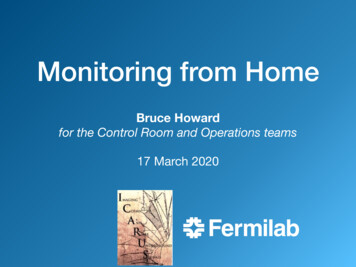
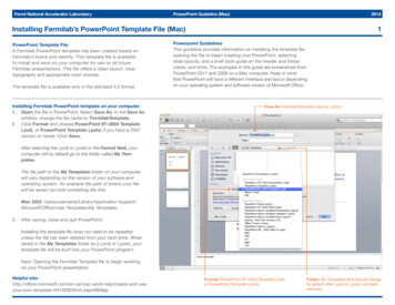
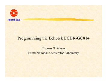
Tevatron BPM Hardware SpecificationsOverviewThis document describes the hardware needed for the data acquisition component of theTevatron Beam Position Monitor (BPM) upgrade project. The data acquisition (DA)hardware will digitize the analog position signal from the BPM sensors, digitally filter thesignals and make them available to a VME front-end computer. The DA could alsoprovide the interface to the Beam Loss Monitor (BLM) circuitry through the ExternalDevice Bus (EDB) to replace the functionality of the existing system. Figure 1 shows thefunctional block diagram and the different elements involved with the BPM upgradeproject.BPM signalsSignalconditioning gBSync ClkVME cratecontrollerH/W&S/WData outACNETClock&GateHardwareTiming ModuleTClk uleTClkS/WFigure 1 BPM Front End Functional Block DiagramThe hardware functions described in Figure 1 are implemented in four modules thatmatch the hardware blocks above. The signal conditioning and diagnostics areimplemented on the Filter module being designed at FNAL. The Digital Signal Receiver(DSR) is a Commercial-Off-The-Shelf (COTS) module from Echotek Corporation, theECDR-GC814/8-FV2. The timing functions are implemented on the VME TimingGenerator Fanout module designed at FNAL. The VME sub rack controller is a COTSSingle Board Computer from Motorola Corporation, the MVME240022/23/05
Tevatron BPM Hardware SpecificationsBeam Position SystemSensorThe Tevatron BPM sensors1 and 2 are two opposing curved stripline plates approximately18 cm long along the beam and oriented to partially surround the beam. Each platesubtends approximately 110 degrees of the full circle around the beam. The circularaperture of the pair (the diameter of the opening) is 6.6 cm. There are connections atboth ends of each plate, one connection emphasizing the proton direction of flight and theother the anti-proton direction. The signal taps are at the ends of the individual plates.The convention for the naming of the four signals from a specific BPM sensor are a letterdesignator for each of the two plates, the A plate, and the B plate, and whether it is theproton end or the anti-proton end. Each of the four BPM signals is treated identically inthis Data Acquisition (DA) system except for a resistive attenuator which matches thesensor voltage to the input voltage range of the Echotek module and can also be used toapproximately match the proton and anti-proton signal amplitude ranges. The signal ofinterest is the amplitude variation of the sensor signals as the beam position moves in thesensor but the amplitudes are also proportional to the number of particles passing throughthe sensor and to the bunch length. In 2004 the bunch size based variation of theamplitude of the proton signals at the proton outputs is approximately 5 times as large asthe anti-proton signal at the anti-proton outputs. The 236 Tevatron sensors are on the endof quadrupole magnets in the beam tunnel and the BPM DA electronics modules are inservice buildings around the ring. 200 to 300 meter long RG-8 cables bring the sensorsignals to the DA system and the Tevatron Filter board.BPM Data Acquisition SystemThe BPM signals pass through the Tevatron Filter board for amplitude conditioning andband pass filtering. The filter is centered at the 53.104 MHz accelerator RF frequencywith a bandwidth of approximately 10 MHZ. The filter specifications are in BeamsDocument #1165. This module also has the capability to switch in a diagnostic signaland drive that signal out to the sensor or back toward the Echotek module input. Bysequentially driving one output of a sensor and digitizing the other three sensor signalsthe general condition of that sensor and its associated cable plant can be determined.Short coaxial cables move the signals from the Tevatron Filter board outputs to theEchotek commercial digital signal receiver module that is the Analog to Digital converterand main signal processing element. On the module, the sensor signals are convertedfrom analog to digital representation, passed to a Digital Down Converter (DDC) signalprocessing chip for base banding, filtering and then placed in memory that is accessiblethrough the VME backplane bus. The data movement is controlled by firmware in areprogrammable FPGA device on the module. The VME sub rack controller is aMotorola MVME2400 type processor that controls the data acquisition process. Thesoftware that resides on the front-end microprocessors, also referred to as the DataAcquisition (DA) software, is described in Beams Document #860, Tevatron BPM12The Tevatron Beam Position and Beam Loss Monitoring Systems (Beams-Doc-806)Fermilab Energy Doubler Beam Position Detector (Beams-DOC-809)32/23/05
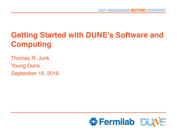
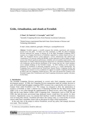
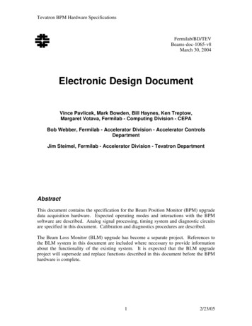
Tevatron BPM Hardware SpecificationsUpgrade Software Specifications for Data Acquisition. The system timing is controlledby the VME BPM Timing Generator Fanout module. The TGF timing is based on threeTevatron timing signals. 1) the Tevatron RF Clock (RFClk) at 53.104 MHz which issynchronous to the Tevatron beam, 2)Tevatron Beam Sync (TVBS), running at 7.5 MHzsynchronous with the RFClk and containing some Tevatron commands and the encodedturn marker, encoded as 0xAA, and 3) Tevatron Clock (TClk) running at 10 MHz andcontaining accelerator-complex-wide commands.The sensor front-end electronics depicted in Figure 1 are contained within a VME subrack holding a series of pairs of Tevatron Filter boards and BPM VME digitizing boards,the BPM Timing Generator Fanout card, the sub rack controller and, if necessary, BLMinterface hardware. Figure 2 illustrates the organization of the cards in the BPM VMEsub rack. One sub rack can hold the necessary electronics needed for a service building(sometimes called a house). There are 30 service buildings or houses around theTevatron ring, 27 of them contain BPM electronics and each BPM house has up to 6BPM digitizing boards. There are also up to 23 BLM digitizing boards in separate analogcrates. Table 6 is the current organization of BPM and BLM sensors relative to theservice buildings.The BPM digitizing modules are Echotek module ECDR-GC814/8-FV2, and eachmodule digitizes signals from 8 channels. An individual BPM sensor generatesinformation on 4 channels – the A and B plates for the proton end of the sensor and the Aand B plates for the antiproton end. Therefore one Echotek module will be capable ofaccepting signals from two BPM sensors. The digitized output that results from eachchannel of the digitizing module may be sent on for further processing or be used togenerate a calculated position when processed with data from the matching plate channel.The details are in the Software Specifications document. If the output is the digitized andfiltered signal data, each channel is actually represented by two components: a real (Q)and imaginary (I) part. The digital filtering on the Echotek module can also be disabledallowing a raw, oscilloscope type view of the signal.The operation of the Echotek module is controlled by two inputs that are common for alleight channels. They are the CLK and SYNC signals. The digitizing clock paces theEchotek module and comes from the BPM Timing Generator Fanout (TGF) Module. Aphase-lock-loop on the Timing module creates a clock output that has a fractionalrelationship to the Tevatron RF clock frequency. TeV RF is approximately 53.104 MHz.The Echotek clock is 7/5ths or approximately 74.346 MHz. This means that the 53.104MHz signal is technically under-sampled but the signals-of-interest are modulated ontothat RF signal and filtering and signal processing techniques allow the module to extractthose signals-of-interest. The digitization process can be gated, singly triggered ortriggered for a specified number of samples by the SYNC signal. SYNCs are generatedin the TGF and normally initiated with respect to the Tevatron-wide TCLK signal whichcarries Main Control Room (MCR) commands and state information. There are twoTCLK decoders in a given sub rack; one on the sub rack controller, implemented in aPMCUCD module mounted on a PMC slot and one implemented within the TGFModule. The TCLK decoder on the TGF can initiate digitizing sequences enabled onselected TCLK commands and can add fixed delays relative to the Tevatron turn marker42/23/05
Tevatron BPM Hardware Specifications( AA), with a resolution of one RFClk period, in order to remove cable delays (with aresolution of one RFClk period) or to time-in similar actions between the widelyseparated service buildings around the Tevatron ring. The TGF card is capable of finerdelay resolutions using the digitization clock or optional Phase Lock Loop outputs.The ACNET/MOOC software infrastructure and applications can also be triggered byinterrupts generated by the same TCLK signals that are decoded by the PCMUCD cardand this is discussed in detail in front-end software design document (#1067).Digital ReceiversTimingCPU GeneratorPMCUCDClock generatorincorporated intoTiming GeneratormoduleTevatron Filter boardFigure 2 Sub Rack Module, Example Configuration52/23/05
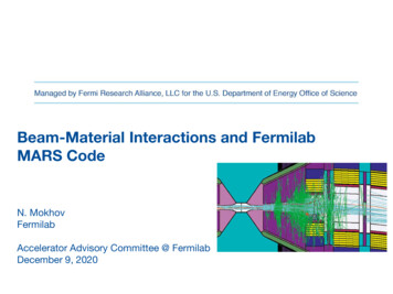
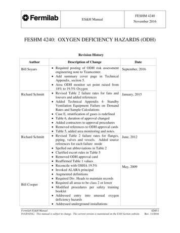
Tevatron BPM Hardware SpecificationsBPM RequirementsThe requirements for this system are based on the system requirements documented inTevatron BPM Upgrade Requirements Document (Beams Doc #554). A summary of thefunctional requirements are: Continuous closed orbit sampling with 1 kHz of IF bandwidth and 500 Hzmeasurement rate.Closed orbit position should be stable for single bunch, multiple bunches anduncoalesed bunches.Turn-by-turn sampling with 100 kHz of IF bandwidth and 47 kHz measurementrate. Store 8192 points/turn-by-turn request.Simultaneous measurement of protons and pbars. Measure pbars with closedorbit sampling and proton de-convolution (no change from closed orbit sampling)or use short gate sampling. Short gate sampling is a technique uses to separateproton signals from anti-proton signals on the same sensor lines. The technique isdescribed in Beams Document #1200.Data AcquisitionFunctional OverviewThe communication between the front-end processor and the Echotek modules happensthrough the VME backplane. If necessary, BLM data is exchanged through a digital I/Ointerface on the TGF board or as an I/O daughter board on the sub rack processor.Data coming from the BPM are stored into a set of buffers in the sub rack controller. Thedepth and number of logical buffers that reside on the sub rack controller is defined in theFront-end Software Design Document (Beams Doc #1067). Some of the buffers, mostnotably the turn by turn data, is first stored in memory on the Echotek boards and thentransferred to the sub rack controller on demand, as the processor/backplane does nothave the bandwidth to acquire it in real time. The actual physical implementation of thesub rack controller buffers will be described in the front-end software design document.Tevatron Filter boardThe Tevatron Filter board conditions the signals from the Tevatron BPM sensors forinput to the Echotek DSR Module. It also provides for injecting a diagnostic signal backinto the sensor, into the Echotek Module, or both. Schematics for the Filter Card can befound in the Tevatron Filter board Appendix.The Filter Card has eight channels so that one module is required for each EchotekModule. Each channel (Figure x) consists of an attenuator network, a band pass filter,and two relays. The BPM signals enter and exit via SMB connectors on the front panel.62/23/05
Tevatron BPM Hardware SpecificationsBand Pass Filt erT At t enuat orINROUTRRELAY 0RSMBSMBDiagnost ic I nRELAY 1Figure 3 Filter Card BPM Channel Block Diagram72/23/05
Tevatron BPM Hardware SpecificationsThe Timing Generator Fanout Card (TGF) controls the relays and provides the diagnosticsignal via bused TTL lines on the VME backplane. The Filter Card has a three positionDIP switch to set the card address. This allows up to eight modules per sub rack. TheTGF Card interface consists of the following lines: TFO A (0-2) – Module Address lines from the TFG.TFO CS* – Card Select line From the TFG, active low.TFO CLK – Clock line from the TFG (2 MHz maximum).TFO DOUT – Serial Data from the TFG.TFO DIN – Serial Data to the TFG.TFO RST* – Reset signal from the TFG, active low.TFO DIAG – Diagnostic signal from the TFG.TFO SP (0-3) – Spare outputs from the TFG.TFO SPIN – Spare input signal to the TFG.The TFG configures the relays by sending a 16 bit serial word to the Filter Card. ItDrives the address lines and Chip Select (A (0-2), CS*) to select a module and thenclocks out the 16 serial bits RC (0-15). The Most Significant Bit (MSB) (RC15) isshifted in first as shown in Table 1. The TFG then raises the CS* line to complete theoperation. The state of the relays is changed on the rising edge of the CS* signal. Thetable matches the two relays, the input relay (R0) and the test signal relay (R1) for eachchannel, as shown in Figure 3 with the RCn bit that controls it. If the bit is a one therelay is activated and switches to the normally open connection. Otherwise it is in thenormally closed position.Table 1Ch8R1 R0RC15 -Ch7Ch6R1 RO R1 R0-Ch5R1 R0-Ch4R1 R0-Ch3R1 R0-Ch2R1 R0-Ch1R1 R0- RC0The Filter Card receives the TTL diagnostic signal from the TFG, buffers it, sends itthrough a low pass filter and then distributes it on a bus to buffers on each of the eightchannels.The Filter Card has the following LEDs on the front panel: SEL – Indicates that the card is currently being address by the TFG (yellow). SW (0-2) – Indicates the setting of the address switches (green). 5V, 12V, -12V – Power supply indicators (green).[Add front panel pictures and signal descriptions]82/23/05
Tevatron BPM Hardware SpecificationsEchotek Data Converter ModuleThe Echotek module ECDR-GC814/8-FV2 is the baseline data converter. This modulebelongs to a general type of modules called Digital Signal Receivers (or Radios) (DSR).These modules have high speed digitizers that convert the analog, usually radiofrequency, inputs into digital information very early in the signal processing. Thisreduces the amount of analog circuitry in the system. The subsequent digital circuitry isused to down convert or base band the RF information, removing the high frequencycarrier (53 MHz in this case) and revealing the information modulated onto that carrier,48 KHz revolution information, 20 KHz betatron signals etc. The base banded signalsare filtered in n stages of digital FIR filters and the output data is stored in a buffermemory on the module. The sub rack processors can readout the data memory over thesub rack VME backplane.The data sheets for module are in the Appendix as Echotek DSR Module.[Add front panel pictures and signal descriptions]92/23/05
Tevatron BPM Hardware SpecificationsTiming Generator Fanout (TGF) ModuleThe Timing Generator Fanout (TGF) is a double width, 6U VME card that generatestiming signals that control and initiate acquisition of the BPM signals. The timing signalsare based on inputs from the accelerator controls clock system. These signal inputsinclude the Tevatron RF Clock (RFClk), Tevatron Beam Sync clock (TVBS) and theTevatron event clock (TCLK).The RFClk is the synchronization time base for the major functionality of the TGF. TheRFClk is used to over sample and decode the TVBS and TCLK signals.The TVBS base frequency is one seventh of the RF Clock (7.5 MHz) Tevatron events areencoded are encoded as an eight bit serial byte onto this carrier and can be extracted fromit. An important event is the revolution timing mark (0xAA). This event allowssynchronization with the pattern of particles circling around the Tevatron ring. Duringcolliding mode, particle bunches are spaced by 2.5 MHz in batches of 12, and foruncoalesed mode they are spaced by 53 MHz in batches of 30.The TCLK signal is very similar to TVBS with a 10MHz carrier frequency and from itthe module can extract a large number of events from the Main Control Room usuallyindicating changes in the state of the Tevatron. The TGF can be programmed to respondto any of up to sixteen selectable events at a time and interrupt the sub rack controller.For each Echotek DSR module the TGF creates a digitization time base clock that pacesthe data conversions and filtering on the board. It also supplies a trigger signal forcontrol of the data acquisition. For the Tevatron BPM system, the TGF multiplies the RFclock frequency by exactly 7/5 to produce the digitization clock. The RF frequency shiftsas the energy of the beam changes. At approximately 980 GeV the RF clock frequency istypically 53.10468 MHz which produces a digitization rate of 74.346552 MHz. Thenormal range of the RF clock is 53.103xxx to 53.104xxx. [The TGF module can alsogenerate other multiples of the RF Clock for the digitization clock, 10/7ths for example.Any multiple other than 7/5ths is created within the FPGA so the quality of the clocksignal is less than that of the signal generated by the on-board clock oscillator.]Digitization triggers will be triggered by and/or delayed from the revolution timing markso that the acquired data are related to the particle bunches and measurements in separateservice buildings are synchronized to each other as necessary.The sub rack controller can be programmed to read out BPM values based on a specificTCLK signal (e.g. TCLK 77 which is a TeV Flash command). The sub rack controllerdoes not receive Tevatron Beam Sync (TVBS) events. In the sub rack controller, thepreparation for digitization and read out is signaled by an arm event. An arm event isusually originated by commands from the MCR. For example, a turn by turnmeasurement could be armed by a TCLK command or state change and then started onthe next ‘AA’ turn marker plus a pre-programmed delay. More information is below inData Acquisition .102/23/05
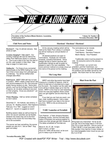
Tevatron BPM Hardware SpecificationsFront Panel ViewTGF 5.0V OnVME SelectRFClk LockedTVBS Event Decoded5.0V3.3VVMEEVENTRFCLKMDATBSYNCTCLK3.3V OnDiagEventMDat Event DecodedTClk Event DecodedJTAGPORTFirmware Download PortInputRFCLK InputRFCLKMDATBSYNCTCLKBSync InputMDat InputTClk InputOutputADC Clock OutputClk0 – Clk7DAC Output (NA)Trig0 CLK5SYNC5CLK6SYNC6CLK7SYNC7DACTRIG2TRIG0TRIG1ADC Sync OutputSync0 – Sync7Diagnostic SignalTo Relay CardTrig1 OutputTurn Marker EventI/O112/23/05
Tevatron BPM Hardware SpecificationsAlso see installation document #1512.Front Panel I/O DescriptionThe Timing Generator Fanout Module inputs are: RFCLK – Tevatron RF Clock (very close to 53.10468 MHz). The RFClk musthave signal level greater than 200mv and capable of driving an ac coupled 50ohm termination. TVBS – Tevatron Beam Sync is an approximately 7.5 MHz carrier with amodified Manchester encoding of Tevatron beam specific events. TVBS must becapable of driving 50-ohms with a signal level greater than 1.2v. TCLK – Tevatron Clock, a 10 MHz carrier modulated by a fixed protocol of bitpatterns that can carry commands and data events to electronics across theaccelerator complex. TClk must be capable of driving 50-ohms with a signal levelgreater than 1.2v. MDAT – A 10 MHz carrier modulated like TCLK to carry additional data andevents. TClk must be capable of driving 50-ohms with a signal level greater than 1.2v. Not required for the BPM project. An External Trigger Input – One possible use of this input trigger is to permit theTVBS decoding to be bypassed by creating a hard trigger rather than a decodedtrigger. Currently used for testing and future expansion. (Opt.) BLM External Device Bus – actually bidirectional but predominately areadout link for data from the Analog Box that processes the signals from theBLM sensors. Not required for the BPM project.The Timing Generator Fanout Module outputs are: A2D Clock signals [0-7] – the digitization clock to the Echotek modules. Theseregenerated clock outputs are based on a signal that is phase locked to the RFClkwith a frequency of RFClk multiplied by 7/5. Output levels are 700mv into 50ohms. A2D Sync signals [0-7] - the synchronization output for a sequence ofdigitization. The Sync output signals have a pulse width of 50ns and are capableof driving a 50-ohm termination. Diagnostic clock – A 53.104 MHz clock or pulse-train (selectable via VMEregister offset 0x100) to the Filter/Diagnostic board for the diagnostic functions.This signal is routed on the VME backplane. An External Trigger Output (Trig1)–Allows an external device to be triggeredfrom an internal firmware trigger condition such as a decoded BSync event. Usedfor testing and future expansion. An External Trigger Output (Trig2)–Same as the diagnostic clock. DAC Output –14-bit DAC for testing and possible future expansion VME Interrupts for signaling the sub rack controller.122/23/05
Tevatron BPM Hardware Specifications Backplane connections that allow the TGF to control the Tevatron Filter boards.These lines will also allow a level of auto-detection on a per sub rack basis so thatthe TGF will ‘know’ how many Filter boards there are to control.The A2D Sync signal variations are: TCLK trigger direct TCLK programmable delay TCLK repeated programmable delay TVBS trigger direct AA (turn marker) detect. TVBS programmable delay TVBS repeated programmable delay External Input Triggered – Similar to above TCLK or TVBS except it is a directtrigger and bypasses the Manchester decoding section.VME Base Address SelectionThe VME interface section of the TGF is capable of 16-bit address and data only. TheVME base address is selectable via a four position dip switch labeled ID3 – ID0 as shownbelow. For the BPM project, only ID1 will be turned off and all the others will be on.This gives a base address of 0x2000 where ID3 – ID0 controls the upper 4-bits of theVME address.TGF FirmwareThe overall TGF firmware will not be changeable remotely. The board will need to bedirectly connected to the programmer workstation or laptop to change the firmware.However the functional programmability is controlled by the following registers that areaccessible over the VME bus by the sub rack controller. All registers are 16 bits widealthough the effective width is noted. Also note that anything labeled MDAT below has132/23/05
Tevatron BPM Hardware Specificationsnot been implemented in the current version of the TeV BPM firmware and there are noplans to implement MDAT decoding in the future.BPM Timing Generator Fanout - Register Map from Offset 0hTable 2I/O ISTERRegister NameAcquisition Bucket Delay 0Acquisition Bucket Delay 1Acquisition Bucket Delay 2Acquisition Bucket Delay 3Acquisition Bucket Delay 4Acquisition Bucket Delay 5Acquisition Bucket Delay 6Acquisition Bucket Delay 7Gate Count 0Gate Count 1Gate Count 2Gate Count 3Gate Count 4Gate Count 5Gate Count 6Gate Count 7Not UsedNot UsedNot UsedTurn Scaler for BackgroundMdat TypeMdat Frame ValueMdat scale factorPre-Trigger Delay AllControlStatusBSync Turn EventBSync Start EventDiagnostics CounterDiagnostic Counter w/ waitMDAT Data sampled on StartBSync Clear Timestamp EventFirst Turn Timestamp (Wrd0)First Turn Timestamp (Wrd1)First Turn Timestamp (Wrd2)14MAPEffective s16-bits6-bitsSee Table 4See Table 58-bits8-bits16-bits8-bitsQuad WordQuad WordQuad /WR/WR/WR/WR/WR/WR/WReadR/WR/WRead OnlyR/WR/WRead OnlyWait on readR/WRead OnlyRead OnlyRead Only2/23/05
Tevatron BPM Hardware 700x720x740x760x780x7A0x7C0x7EFirst Turn Timestamp (Wrd3)TurnsCount (Low)TurnsCount (High)BSync Turn # Missing (Low)BSync Turn # Missing (High)SwitchTimeStamp CounterTurns CounterTClk TimeStamp EventTClk TimeStamp Wrd0TClk TimeStamp Wrd1TClk TimeStamp Wrd2TClk TimeStamp Wrd3Irq Vector Reg 1Irq Vector Reg 2Last Interrupted TClk EventTClk IRQ #Wrds PendingQuad WordLow High 32Low High 32Low High 32Low High 32Low wordLow word8-bitsQuad WordQuad WordQuad WordQuad WordSee Figure 4See Figure 48-bits8-bitsIRQ1 Source MuxIRQ2 Source MuxSee Table 3See Table x980x9ATClk Event0TClk Event1TClk Event2TClk Event3TClk Event4TClk Event5TClk Event6TClk Event7TClk Event8TClk Event9TClk Event10TClk Event11TClk Event12TClk Event13Memory Address RegisterRead OnlyRead OnlyRead OnlyRead OnlyRead OnlyRead OnlyRead OnlyRead OnlyR/WRead OnlyRead OnlyRead OnlyRead OnlyR/WR/WRead /WR/WR/WR/WR/WR/WR/WR/WR/WR/WR/WR/WR/WR/W2/23/05
Tevatron BPM Hardware Specifications0x9C0x9ETClk Event14TClk E0xB00xB20xB40xB60xB80xBA0xBC0xBEBSyncEvent(00 0F) FoundBSyncEvent (10 1F) FoundBSyncEvent (20 2F) FoundBSyncEvent (30 3F) FoundBSyncEvent (40 4F) FoundBSyncEvent (50 5F) FoundBSyncEvent (60 6F) FoundBSyncEvent (70 7F) FoundBSyncEvent (80 8F) FoundBSyncEvent (90 9F) FoundBSyncEvent (A0 AF) FoundBSyncEvent (B0 BF) FoundBSyncEvent (C0 CF) FoundBSyncEvent (D0 DF) FoundBSyncEvent (E0 EF) FoundBSyncEvent (F0 FF) 60xD80xDA0xDC0xDETClkEvent(00 0F) FoundTClkEvent (10 1F) FoundTClkEvent (20 2F) FoundTClkEvent (30 3F) FoundTClkEvent (40 4F) FoundTClkEvent (50 5F) FoundTClkEvent (60 6F) FoundTClkEvent (70 7F) FoundTClkEvent (80 8F) FoundTClkEvent (90 9F) FoundTClkEvent (A0 AF) FoundTClkEvent (B0 BF) FoundTClkEvent (C0 CF) FoundTClkEvent (D0 DF) FoundTClkEvent (E0 EF) FoundTClkEvent (F0 FF) R/W0X1000X1020X1040X1060X108FilterCard Control RegisterRelay Data, Card 0Relay Data, Card 1Relay Data, Card 2Relay Data, Card 3See Table 7See Table 8See Table 8See Table 8See Table 816R/WR/WR/WR/WR/WR/WR/W2/23/05
Tevatron BPM Hardware Specifications0X10A0X10C0X10E0X110Relay Data, Card 4Relay Data, Card 5Relay Data, Card 6Relay Data, Card 7See Table 8See Table 8See Table 8See Table 422ID ROMx0054, “T”x0047, “G”x0046, “F”x0000, “ “x0056, “V”x0045, “E”x0052, “R”x0053, “S”x0049, “I”x004F, “O”x004E, “N”x0000, “ “x0032, “2”x002E, “.”x0030, “0”x002E, “.”x0032, -bit8-bit8-bitR onlyR onlyR onlyR onlyR onlyR onlyR onlyR onlyR onlyR onlyR onlyR onlyR onlyR onlyR onlyR onlyR onlyR onlyR only172/23/05
Tevatron BPM Hardware SpecificationsTable 3IRQ SOURCE x090x0ANullStart EventRevolution EventMDAT Type MatchTurn Counter Trigger OutDelay Timer EnabledDelay Timer TriggerDelay Timer Terminal CountTurn Counter TriggerPeriodic timer (BGFlash rate)TClk Event MatchI/OAddress0x70.0x7216-bitsR/WINTERRUPT STATUS/ID REGISTER DETAIL (Eight instances)D15 . . . . . . . . . . . . . . . . . . . . . . . . . . . . . . . . . . . . . . . . . . . . . . . . . . . . . . . . . . . . . . . . . . . . . D0VECTORINTERRUPT PENDINGFLAG AUTO CLEARFLAGX X 0/1IP IRQ LEVELINTERRUPT AUTO CLEARIRQ ENABLE 1, IRQ DISABLE 0Figure 4182/23/05
Tevatron BPM Hardware SpecificationsTable 4CONTROLAND MODEREGISTERI/O Address 0x30DATALow 4]Control[5]Control[6]Control[7]Enable Pre-Trigger CounterEnable Delay TimerNot UsedNot UsedTrigger SourceTrigger Source“Start” Source“Start” SourceHigh l [12]Control[13]Control[14]Control[15]Not UsedEnable TClkEnable Beam SyncNot UsedSingle/Repetitive ADC Sync OutNot UsedReset TClk IRQ PendingReset TSGZero Disabled, One EnabledZero Disabled, One EnabledZero PreTrigger, One External,Two Start EventZero Start Event, One Null,Two Turn Scaler (periodic)Zero Disabled, One Enabled**Zero Disabled, One EnabledZero Repetitive, One SingleZero Disabled, One EnabledZero No action, One Reset** Proposed ChangeControl Register Comments:Control(7:6)When equal to “00”, the Start Source is the BSync start event register (0x36) is equal thedecoded BSync serial input.When equal to “01”, No Start Source.When equal to“10”, Start is generated when the turn scaler counter (0x26) is equal tozero. The Turn scaler counter is decremented by the decoded BSync Turn event.Control(12)When
Jim Steimel, Fermilab - Accelerator Division - Tevatron Department Abstract This document contains the specification for the Beam Position Monitor (BPM) upgrade data acquisition hardware. Expected operating modes and interactions with the BPM software are described. Analog signal processing, timing system and diagnostic circuits