Transcription
INSTALLATION GUIDEQDM-05-000051Control Panel 2.0 Installation GuideProduct DescriptionThe View Control Panel 2.0 houses the controlcomponents and power source that areresponsible for the operation of a View system.There are two configurations of the panel,one supporting up to 128 window controllers,with six Class 2 circuit outputs, and the othersupporting up to 256 window controllers withtwelve Class 2 circuit outputs. Additionally,each control panel includes a six-port Layer 3Ethernet switch to allow for interconnection ofthe panels on a private VLAN and support forup to two IEEE 802.3af midspan injectors forconnection of View sensors.intelligencePurposeThe purpose of this Guide is to provide explanations and procedures for installing, configuringand operating the View Control Panel 2.0 (CP 2.0)Package Includes1. Control Panel 2.02. Four (4) mounting brackets, one for each corner of the Control PanelScopeThis Guide provides safety guidelines, detailed planning installation instructions and setupinformation for installing the View Control Panel 2.0. Determining the location and placement Mounting the Control Panel Adding Power to the Control PanelNote: The Control Panel weighs 70 lbs, recommend 2-person handling (lifting) when movingor installing the Control Panel.Rev 2 Mar 20192019 View, Inc. 1 of 8
INSTALLATION GUIDEQDM-05-000051AudienceThis guide does not provide sufficient information for anyone but a C10 qualified installerto install this product. Installers should be licensed electricians familiar with the hazards ofinstalling electrical equipment.Optional Accessories1. Pull Box - PN: 010-1016112. PoE Injector PoE 1: 015-101821-01 PoE 2: 015-101821-023. SFP Kits 850 mm PN: 015-101844-01 1310 sm PN: 015-101844-02 1000 base T PN: 015-101844-03Abbreviations and AcronymsNEC - National Electric Code (NFPA 70)NFPA79 - Standard for Industrial Control Panels (NFPA 79)UL508 - Underwriters Laboratories Standard UL-508CEC - Canadian Electric CodeCSA - Canadian Standards AssociationDC - Direct CurrentFCC - Federal Communications CommissionNFPA - National Fire Protection AssociationSFP - Small Form Factor PluggableVAC - Volts ACVDC - Volts DCLOTO - Lock-Out, Tag-OutAdditional Supporting Documentation1. Control Panel 2.0 Data Sheet - QDM-02-0000332. Pull Box 2.0 Data Sheet - QDM-02-000037Rev 2 Mar 20192019 View, Inc. 2 of 8
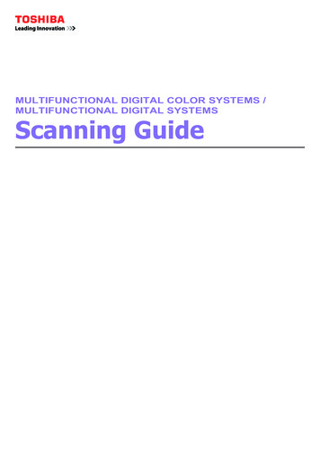
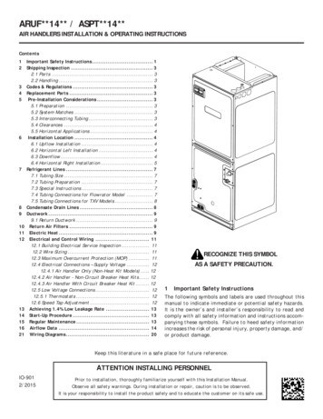
INSTALLATION .99”29.96”29.02”intelligenceRev 2 Mar 18J21J19J222019 View, Inc. 3 of 8
INSTALLATION GUIDEQDM-05-000051InstallationStep 1: Identify installation location1. The Control Panel should be placed in the location determined by the General Contractoras seen on the Interconnect Drawings (schematics). If there are multiple Control Panelsfor the installation, they will each be marked on the front panel with their designatedlocation and labeled to coincide with the Interconnect Drawings.2. Before mounting the Control Panel to the wall, be sure there is enoughclearance provided to install the Trunk Line and Power Insert cables as required.3. Mounting surface must be capable of handling the weight of the unit (70lbs).Recommend mounting surface ¾” Fire Retardant Rated plywood. Securely mount theControl Panel using the 4 mounting tabs onto the wall according to local building coderequirements for mounting 70lb. enclosure.4. The Control Panel should be mounted with sufficient working clearances. Per NECArticle 110.26: a) the top of the Control Panel should be no higher than 2m (6.5 ft. A.F.F.above finished floor), including the pull box if one is used; b) 15 in. of clear space fromthe vertical center-line of the panel to the sides; c) 36 in. of clearance in front of thepanel.Step 2: Connecting Power1. Refer to the control panel schematic (340-101695) provided in the document pocketon the door of the control panel for details of the AC connections and locations2. The View Control Panel is rated for 120-240VAC, single phase operation (Line, Neutraland Ground). This product cannot be used in 3-phase circuits (e.g. 208VAC wye ordelta connections).3. Installation requires an upstream (facility panelboard) UL-489 branch circuit protectionsufficient to provide 20A (at 120VAC, 10A for 240VAC) for the control panel (perNEC Article 409.21 A-1), marked as disconnect device for the control panel. Thisunit can also be installed in jurisdictions that specify IEC 60947-1 and IEC 60947-3Each View control panel requires a “DEDICATED” 20-amp circuit, do NOT shareground or neutral with other circuits.4. Lock-out and Tag the facility disconnect before proceeding5. Open the front panel to reveal the inside of the Control Panel.Rev 2 Mar 20192019 View, Inc. 4 of 8
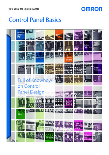
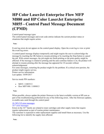
INSTALLATION GUIDEQDM-05-0000516. Turn CB1 off (lever in the down position )DOWNLABELLCB1TB1NGND7. Remove the protective panel covering CB1REMOVEUSE COPPER CONDUCTORS ONLYTEMPERATURE RATING OFTHE FIELDWIRING CONDUCTORS: 75 CTERMINALTIGHTININGTORQUE: 20 in-lbWiring Instructions: Turn off powerbefore doing any work on panel.Remove AC shield to access mainCircuit Breaker and AC Terminals.LNLCB1TB1NGSERVICE ONLY, 5A MAX.FUSE RATING OF 250V, 6.3AGNDLABELLCB1Rev 2 Mar 2019TB1NGND2019 View, Inc. 5 of 8
INSTALLATION GUIDEQDM-05-0000518. Install flexible or rigid (EMT) 1/2” conduit (per NEC Ch9, Annex C, table C.1) to portshown 0J18J21J19J229. Conduit installation should resemble the configuration belowEMT1/2”intelligence10. Furnish Line, Neutral, and ground wiring from the upstream panelboard to the CP.Typically this should be 12AWG THHN wire per NEC table 310.15(B).Rev 2 Mar 20192019 View, Inc. 6 of 8
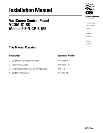
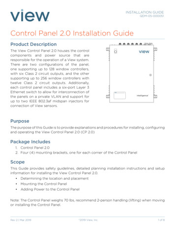
INSTALLATION GUIDEQDM-05-00005111. Connect the facility ground (green or green/yellow wire) to the ground stud designatedby the PE ground symbol in the top left of the enclosure. Termination will require a ringterminal for a #10 or M5 stud.12. Connect Line to the top of CB1, tighten the screw to 20 in-lbs13. Connect Neutral to one of the open positions of TB1-N Tighten the screw to 20 LTB1NTB1TB1TB2OFFRev 2 Mar 20192019 View, Inc. TB27 of 8
INSTALLATION GUIDEQDM-05-00005114. Verify there are no shorts between Land N, and between L and ground15. Close the panel door and energize theenclosure by removing the LOTO andswitching power on16. With the appropriate PPE (as specifiedby NFPA 70E) open the enclosure andverify a reading of 120 to 240VAC ispresent between the line side of CB1and N17. De-energizetheenclosurebyreapplying the LOTO18. Replace the protective panel removedin step 719. Turn CB1 ON by moving the lever tothe UP position.UP20. Close the Cabinet door.21. Remove the LOTO and re-energize the panel.Verify the green light is illuminated on the front of the Control Panel. Once verified, turnthe Control Panel off.POWERPOWERintelligence22. Final commissioning to be completed by View FSE only.Rev 2 Mar 20192019 View, Inc. 8 of 8
Control Panel using the 4 mounting tabs onto the wall according to local building code requirements for mounting 70lb. enclosure. 4. The Control Panel should be mounted with sufficient working clearances. Per NEC Article 110.26: a) the top of the Control Panel should be no higher than 2m (6.5 ft. A.F.F.