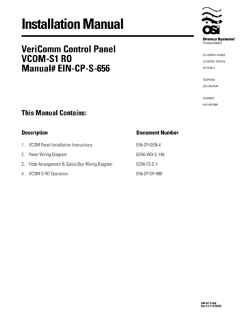
Transcription
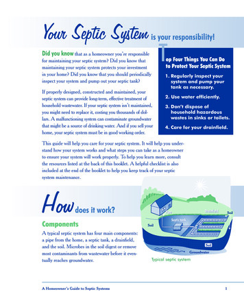
Installation ManualVeriComm Control PanelVCOM-S1 ROManual# EIN-CP-S-656This Manual Contains:DescriptionDocument Number1. VCOM Panel Installation InstructionsEIN-CP-GEN-42. Panel Wiring DiagramEDW-WD-S-1483. Float Arrangement & Splice Box Wiring DiagramEDW-FS-S-14. VCOM-S RO OperationEIN-CP-OP-498EIN-CP-S-656Rev 2.0 01/02/02
VCOM Panel InstallationThis document contains general installation instructions for VeriComm control panels. Consult allsupplemental documents (Control Panel Wiring Diagram, Float Arrangement Diagram, etc.) beforeinstallation. Follow the outlined sequence below. Getting StartedRead all instructions before proceeding with theinstallation. Improper installation may void warranties.1. Inspect your order for completeness and inspect each component forshipment damages. If something is missing or damaged, contactyour supplier to obtain replacement parts.2. Check to ensure the instructions and items supplied conform to stateand local regulations.3. A qualified electrician must be employed to install and service thepanel and ancillary wiring. The equipment must be installed incompliance with the National Electric Code, as well as state andlocal codes.The VCOM panels are part of the VeriCommproduct line, and work in conjunction withthe VeriComm Monitoring System. Control Panel PlacementCONTROLPANEL1. Physical installation of the control panel should be within view of theseptic tank and located at a convenient height (about five feet abovegrade).ControlPanel5 Feet2. The panel should be securely fastened to a 4 x 4 post that has beenconcreted into the ground. Alternatively, the panel can be fastenedto an exterior wall, subject to the restrictions below:4x4Post If the panel contains motor contactors, a thumping sound can beheard each time the pump is started or stopped. Therefore, thesepanels should not be mounted on an exterior wall unless it is in alocation away from living areas, such as on a garage wall.Concrete3 Feet3. If possible, position the panel in the shade to protect it from weather.Extreme temperatures can cause inconsistent performance of theelectrical components.MountingBracket4. Check state and local electrical codes for proper placement of panels.Ensure that access to the panel is not obstructed.EIN-CP-GEN-4Rev. 3.1, 08/01/05 Orenco Systems , Inc.Page 1 of 3
Float and Pump Installation1. Install the electrical splice boxes for the floats and pumps beforeinstalling the actual floats and pumping equipment. The splice boxesare installed near the top of the riser, using the grommets provided. Do not remove the colored2. Install the floats. Thread the float and pump cords through the cordgrips into the PVC splice box, leaving adequate length of electricalcord coiled inside the riser to allow easy removal of the pump andfloat assembly. Do not thread the markers andmarkers or the paper tags fromthe float cords. These shouldbe left on the float cord,outside the splice box.tags through the cord grips.3. Tighten the cord grips, using hand pressure or a wrench if necessary,until the cord will no longer move in the cord grip. If the cord gripsare not tight enough, the seal will not be watertight, but overtightening may damage the cord or the cord grip, so use only asmuch force as necessary.4. Run the wires from the control panel to the splice box. The wirescan be brought through a conduit, or can be buried using suitabledirect-burial wire. Conduit that enters the splice box must be sealed,even if the wires are direct-buried, to prevent the infiltration of waterinto the splice box. Use an electrically approved sealant to plug thewires coming in through the conduit hub. The number of wiresrequired depends on the control panel and the number of floats andpump(s) used. Adequate length of cordshould be left within the splicebox to allow for easy removalfor future disconnecting andre-splicing. A cord is secure and theconnection watertight when thecord grip is tight enough toprevent slippage.Consult the appropriate float arrangement diagram for the controlpanel and float arrangement being used.Wire should be sized at 14 AWG for the floats. Refer to the figurebelow to determine the proper size for the pump wires. Whencalculating wire size, the length and size of your branch circuit wiresfrom the service entrance panel to the pump control panel must alsobe taken into account. Wire that is improperly sizedRecommended Breaker & Wire SizePump Motor Size120 VAC 1/2 hp240 VAC 1/2 hp3/4 hp1 hp1-1/2 hp*Breaker SizeWire SizeMax Distance*20 amp15 amp20 amp20 amp20 amp10 AWG14 AWG14 AWG12 AWG12 AWG105 ft161 ft130 ft172 ft126 ft(too small) can cause excessivevoltage drop and poor pumpperformance.This is the maximum distance from this sub-panel to the pump motor for therecommended wire size. Distance is based on 3% maximum voltage drop from sub-panelto load at maximum recognized pump motor amps at 75 C.5. All splices made in the splice box should use waterproof wire nuts orbutt connectors and heat shrink tubing. Refer to Drawing EIN-SBSB-1 for instructions on making waterproof splices. Refer to theappropriate float arrangement diagram for instructions on how toconnect the floats together. Splices that are not waterproofmay cause a malfunction of thepump controls if water shouldleak into the splice box.EIN-CP-GEN-4Rev. 3.1, 08/01/05 Orenco Systems , Inc.Page 2 of 3
Control Panel Connections1.Connect the wires coming from the floats to the terminals in thecontrol panel. Refer to the appropriate float arrangement diagram forthe correct terminal connections for your system.2.Connect the wires coming from the pumps to the pump terminals.Refer to the panel wiring diagram for the correct terminalconnections for your system.3.Connect the incoming power to the panel. Power to the panel mustbe appropriate to the control panel and pump motor (120 VAC,single-phase for a 120 VAC motor, 240 VAC single-phase for a 240VAC motor, etc.).4.Ensure that the panel is properly grounded and that the fuse orbreaker and wire size, from the main power panel and to the pump,are correctly sized. A separate circuit for the pump controls and eachof the pump motors is recommended.NOTE: Voltage for the controls in the panel is always 120 VAC,although the pump voltage may be 120 VAC or 240 VAC.5. Use 60 minimum CU conductors only. Torque the terminal blocksto 15 LB-IN and the ground lugs to 45 LB-IN. Torque the circuitbreakers to 20 LB-IN for 14-10 AWG wire, 25 LB-IN for 8 AWGwire, and 27 LB-IN for 6-4 AWG wire. Telephone Line InstallationThe VeriComm control panels utilize a common phone line with thehomeowner. These panels do not require a dedicated phone line.1. Install a standard analog line from the homeowner’s phone splicebox to the VeriComm control panel.Recommended Part:Outdoor 4-conductor phone cableRadio Shack Cat. #: 278-3862. If an RJ-11 crimping tool is available, crimp anRJ-11 plug directly to the phone wire. Connectthe phone line to the jack on the surgearrestor/DSL filter in the panel.Do not service the pump or anyelectrical wiring in the pump vaultwithout disconnecting the powerat the circuit breaker and/or fuse.Serious injury and/or damage tothe system could result if the panelis not properly grounded. Ensurethat the fuse, breaker, and wiresize—from the main power paneland to the pump—are sizedcorrectly.The pump vault is a hazardous areaand may contain explosive gases.Take appropriate precautionsaccording to local, state, andfederal regulations beforecommencing work in the pumpvault.It is the responsibility of theinstaller to comply with all local,state, and federal regulations thatmay govern the installation ofsystems of this nature. Failure tocomply with such regulations mayvoid the manufacturer’s warrantyand could possibly cause bodilyinjury. Phone wires should not be runin the same conduit as powerwires. The phone line surge arrester /DSL filter requires a goodconnection to ground to beeffective. Ensure that this subpanel is effectively groundedto the service panel.3. If an RJ-11 crimping tool is NOT available, the red and green phonewire can be terminated at terminals “R” and “T”. The red wireshould be connected to “R” and the green to “T”.EIN-CP-GEN-4Rev. 3.1, 08/01/05 Orenco Systems , Inc.Page 3 of 3
Control Panel Wiring DiagramModel VCOM-S1 ROKey Factory Wire Field Wire Alternate Field Wire Audio Alarm, 115 VACAAL Alarm LightAS Audio Silence SwitchCCB Controls Circuit BreakerDF Fuse, 120VAC/1A Motor ContactorMPCB Pump Circuit BreakerPSA Phone Line Surge ArresterRTU ATRTU-100 ControllerTL Terminal LinkTR Transformer 120-36/18VACOptions* )123J3DO4(4)J1DO3(3)DO2(2)DO1(1) Heater Power Light Pump Run Light Surge ArresterCOM )DI6(14)DI7(15)DI8(16)RET(17)RET TB1(18)X2GPLX1Telephone Line ConnectionTR13M14Remote Alarm ConnectionsPSAASOrenco ModelConnect phone line to ATRTU-100RJ-11 jack on phone linesurge arrestor/DSL filter.MMT134For float arrangement diagram,see drawing no."EDW-FS-S-1".56NN1CCB10APCB20AGreenN N1Controls Pump Controls PumpNeutral NeutralL1L11020ONONN N1GroundL1GroundWireNutNeutralPump L1Factory default.Wire as shown.GroundNOTE: Motors must haveinternal overload protection20ONControls L1Pump115 VAC / 1 Hp.1 Phase / 60 Hz.From Main Power Panel115 VAC, 1 Phase, 60 Hz.Main disconnectprovided by cuuuiiitttGroundLugPump NeutralControls NeutralPhoneLineInDFPower Wiring OptionsTTTwwwoooCCCiiirrrcccuuuiiitttsssT2Orenco ModelAHW or equiv.CONTROLSTerminalStripSANNote: 115VAC signal is presentduring alarm conditions.HTL20Remote AlarmLight AlarmOptions*L1For VCOM-S ROoperation description,see drawing no."EIN-CP-OP-498".Use one wire nut to connect the pole ofthe pump circuit breaker together withthe controls breaker and with theincoming L1 power line. Use anotherwire nut to connect the neutral block ofthe pump with the controls neutral blockand with the incoming neutral line.EDW-WD-S-148Rev. 6.0 05/01/07
Float & Splice Box Wiring DiagramFloat Arrangement1234Splice Box WiringTerminal StripTo Terminal#6To Terminal#5High Level Alarm /Pump On(YB)-Yellow &BlueTo GroundTerminalCord GripHand tighten each cord gripso that the cord will not easilyslide through the grommet.Pump OffR-RedTo Terminal#3Redundant Off &Low Level AlarmW-WhiteY BHigh Level Alarm /Pump OnTo Terminal#4Pump CordFloat TypesTypical Orenco float model: ASpecs: contact - normally opendifferential - no minimumpower rating - signalRWTo Terminal#2Pump OffTo Terminal#1Float Tag WhiteNote: Multi-function floats will havemore than one markerRedundant Off &Low Level AlarmKeyBlack WireWhite WireGreen WireAttention: Failure to follow splicinginstructions will void warrantyWaterproofWire NutHeat Shrink &Butt Connector ** Refer to drawing EIN-SB-SB-1for splicing instructions.Control Panel SeriesFloat Function Color CodeSplice Box ModelDrawing No.VCOM-S RO(YB)RWSB4EDW-FS-S-1EDW-FS-S-1Rev 1.0 02/06/01
VCOM-S RO Panel OperationOverviewInput & Output DefinitionsThe VCOM-S RO telemetry-enabled panel isused for remote monitoring and control of ondemand simplex pumping operations.The following inputs and outputs have been used with your control panel:Basic control logic manages the day-to-dayfunctionality of the control panel. As the tankfills with effluent, floats activate a dischargepump. A pump cycle starts when the top float israised by effluent, and ends when the middlefloat drops.Fault conditions are automatically reported tothe VeriComm Monitoring System and notlocally at the panel, making the system virtuallyinvisible to the homeowner. However, if faultconditions are not responded to, or the systemcannot communicate with the VeriCommMonitoring System, then local alarms may beactivated.To silence local alarms, press the “Push-ToSilence” button until the audible alarm stops.The procedures outlined in the remainder ofthis document are to verify properinstallation; they should be conducted in thesequence outlined while in “Test Mode”.Note:1. Digital inputs are the yellow LEDs horizontally aligned along the bottom of the controller,2. Digital outputs are the red LEDs vertically aligned on the right side of the controller, and3. Inputs and outputs are activated by various events (e.g., Floats are activated when the float is in the upposition, “Push-To-Silence” is activated when the push button, located on the front of the panel is pressed).EIN-CP-OP-498Rev 1.2 07/29/05Page 1 of 3
Verify System Status System Data Logs are suspended.In test mode, the floats will function as described: Ensurethat the panel installation instructionshave been completed.High Level Alarm /Pump On (top float): Whenlifted, this float turns the pump on. The pump willcontinue to run until the Pump Off float is lowered.This float also activates the alarm light (steady) andaudible alarm when lifted for more than 10 seconds.Pressing and holding the illuminated “Push-ToSilence” button on the front of the control panel willsilence the audible alarm. The alarm light willremain on (steady) until the float is lowered. Verifythat the circuit breakers are in the onposition. Verify controllerstatus. The “Power LED”located on the controller (see Fig. 1, pg. 1)will either be: Blinking – indicates that the controller isoperating normally, or Solid Off (when power is applied) –indicates that there is a possible problemwith:1. The input fuse on the PC board,2. The main fuse located inside thepanel,3. The controls circuit breaker locatedinside the panel, or4. The incoming line voltage.Enable Test ModeWhile in test mode, the alarm light will be flashing ifthere is NOT an alarm condition present. During analarm condition the alarm light will be steady. Holdthe “Push-To-Silence” button on thefront of the panel until the audible alarmsounds (approximately 15 seconds) to enabletest mode. Digital input #5 should be illuminatedwhen the button is held in. When the audible alarm sounds toindicate that the panel is in test mode,release the button. Whilein test mode, the panel will operate inthe following manner. The Call Home function is disabled, Local audible and visual alarms areactivated as alarm conditions occur, andFloat TestPump Off (middle float): When lowered, this floatturns the pump off.Manual Pump Test Verifythat the pump is submerged in waterbefore continuing. If the RO (bottom) floatdrops, the alarm should sound. Pressdown the spring-loaded“MAN/AUTO” switch located inside thepanel. The pump should immediatelyactivate. For verification: Digital input #6 should illuminate (seeFig. 1, pg. 1), indicating that theauxiliary contact is on.Redundant Off & Low Level Alarm (bottomfloat): When lowered, this float turns the pump off.This is a secondary off float that will operate if thePump Off float fails. This float also activates thealarm light (steady) and the audible alarm. Pressingand holding the illuminated “Push-To-Silence” buttonon the front of the control panel will silence theaudible alarm. The alarm light will remain on(steady) until the float is lifted. Measurethe voltage and amperage of thepump. Measure the voltage at the pumpterminals in the panel while the pumpis running. A low voltage conditioncould indicate that the site wiring isimproperly sized. Using a loop ammeter, place theammeter clamp around the loop of wirelocated above the pump circuit breaker.The amperage should be within thespecifications of the pump.EIN-CP-OP-498Rev 1.2 07/29/05Page 2 of 3
To perform the following test, sufficient effluent isrequired. If there is not enough effluent in the tank,turn the Pump Circuit breaker off.To test the functionality of the floats and ensure thatthe panel is installed correctly, follow the stepsbelow:1. RO/Low Level Alarm Float Test Pullthe float assembly out of the pump vaultand position it so that all the floats are in thedown position. Digital inputs #1, #2, and #3 should NOTbe illuminated. The alarm light should be on (steady);the audible alarm may be sounding. Liftand secure the bottom float in the upposition. Digital input #1 should be illuminated. Within a few seconds, the audible alarmshould shut off and the alarm lightshould be flashing.2. Pump Off Float Test Liftand secure the middle float in the upposition. Digital input #1 and #2 should beilluminated. After a short interval (within 10seconds), the audible alarm and alarmlight (steady) should activate. Digitaloutputs #2 and #3 should also beilluminated at this time. Drop the top float and ensure that it is now inthe down position. The audible alarm should stop after a fewseconds and the alarm light should beflashing. Digital outputs #2 and #3should NOT be illuminated. The pump should continue pumping asindicated by digital output #1 and digitalinput #6 being illuminated.4. Deactivating the Pump Dropthe middle float and ensure that it isnow in the down position. The pump should stop. This is indicatedby digital output #1 NOT beingilluminated. Digital input #1 should remainilluminated; indicating that the RO(bottom) float is in the up position. Reinstallthe float assembly into the pumpvault. Ensure that the floats are free fromentanglement (e.g., float cords, etc). Once the communication session hasended, the modem will automaticallydisconnect. If the LED does not illuminate within thespecified time, verify that the phone linehas a dial tone. This can be done byhooking up a phone to the line that isgoing into the panel.Disable Test Mode (optional) Thepanel will automatically disable testmode and return to normal operation after 30minutes. To disable test mode immediately,hold the “Push-To-Silence” button on thefront of the panel until the audible alarmsounds (approximately 15 seconds). Digital input #5 should be illuminatedwhen the “Push-To-Silence” button isheld in. When the audible alarm sounds toindicate that the panel is no longer in testmode, release the button. Ensurethat the tank has enough water tomaintain the RO (bottom) float in the upposition.3. Pump On/High Level Alarm Float Test Liftand secure the top float in the upposition. Digital inputs #1, #2, and #3 should beilluminated. The pump should activate (within 2 to 4seconds), indicated by digital output #1and the auxiliary contact (digital input#6) being illuminated.Communication Test Pressand release the “Push-To-Silence”button 15 times within a one-minute period.This instructs the panel to call the VeriCommMonitoring System. A red LED (see Fig. 1, pg. 1 - ModemActivity) should illuminate, indicatingthat the controller has establishedcommunication with the host (this maytake a couple of minutes).EIN-CP-OP-498Rev 1.2 07/29/05Page 3 of 3
VCOM-S RO Reference ChartVCOM-S RO Reference ChartProgram: S1RO System 3.1Program: S1RO System 3.1Input Functions (Yellow):1. RO & Low Level Alarm Float2. Pump Off Float3. High Level Alarm/ Pump On Float4. Not used5. Push to Silence6. Auxilliary ContactOutput Functions (Red):1. Pump2. Alarm Light3. Audible AlarmConditions for activation:Float in up positionFloat in up positionFloat in up positionPushbutton is pressedMotor contactor is activatedCondition for activation:Pump is activatedAlarm Light is activatedAudible Alarm is activatedInput Functions (Yellow):1. RO & Low Level Alarm Float2. Pump Off Float3. High Level Alarm/ Pump On Float4. Not used5. Push to Silence6. Auxilliary ContactOutput Functions (Red):1. Pump2. Alarm Light3. Audible AlarmConditions for activation:Float in up positionFloat in up positionFloat in up positionPushbutton is pressedMotor contactor is activatedCondition for activation:Pump is activatedAlarm Light is activatedAudible Alarm is activatedTest Mode:The panel should be put in test mode during maintenance activities,troubleshooting, or panel start-up. To enable test mode, hold the silencebutton on the front of the panel until the audible alarm sounds (about 15seconds). When testing is complete, the panel can be put back into normaloperation by again holding the silence button until the alarm sounds, orthe panel will automatically exit test mode after 30 minutes.Test Mode:The panel should be put in test mode during maintenance activities,troubleshooting, or panel start-up. To enable test mode, hold the silencebutton on the front of the panel until the audible alarm sounds (about 15seconds). When testing is complete, the panel can be put back into normaloperation by again holding the silence button until the alarm sounds, orthe panel will automatically exit test mode after 30 minutes.Forcing a Call:To force the panel to call out, push the silence button on the front of thepanel 15 times within a one minute period. Allow five minutes for the callto be initiated. Once the panel has made a successful connection, the red“CD” light on the board should be illuminated. The red light remainsilluminated until the call has completed.Forcing a Call:To force the panel to call out, push the silence button on the front of thepanel 15 times within a one minute period. Allow five minutes for the callto be initiated. Once the panel has made a successful connection, the red“CD” light on the board should be illuminated. The red light remainsilluminated until the call has completed.EIN-CP-REF-86Rev 1.1 03/12/07EIN-CP-REF-86Rev 1.1 03/12/07VCOM-S RO Reference ChartVCOM-S RO Reference ChartProgram: S1RO System 3.1Program: S1RO System 3.1Input Functions (Yellow):1. RO & Low Level Alarm Float2. Pump Off Float3. High Level Alarm/ Pump On Float4. Not used5. Push to Silence6. Auxilliary ContactOutput Functions (Red):1. Pump2. Alarm Light3. Audible AlarmConditions for activation:Float in up positionFloat in up positionFloat in up positionPushbutton is pressedMotor contactor is activatedCondition for activation:Pump is activatedAlarm Light is activatedAudible Alarm is activatedInput Functions (Yellow):1. RO & Low Level Alarm Float2. Pump Off Float3. High Level Alarm/ Pump On Float4. Not used5. Push to Silence6. Auxilliary ContactOutput Functions (Red):1. Pump2. Alarm Light3. Audible AlarmConditions for activation:Float in up positionFloat in up positionFloat in up positionPushbutton is pressedMotor contactor is activatedCondition for activation:Pump is activatedAlarm Light is activatedAudible Alarm is activatedTest Mode:The panel should be put in test mode during maintenance activities,troubleshooting, or panel start-up. To enable test mode, hold the silencebutton on the front of the panel until the audible alarm sounds (about 15seconds). When testing is complete, the panel can be put back into normaloperation by again holding the silence button until the alarm sounds, orthe panel will automatically exit test mode after 30 minutes.Test Mode:The panel should be put in test mode during maintenance activities,troubleshooting, or panel start-up. To enable test mode, hold the silencebutton on the front of the panel until the audible alarm sounds (about 15seconds). When testing is complete, the panel can be put back into normaloperation by again holding the silence button until the alarm sounds, orthe panel will automatically exit test mode after 30 minutes.Forcing a Call:To force the panel to call out, push the silence button on the front of thepanel 15 times within a one minute period. Allow five minutes for the callto be initiated. Once the panel has made a successful connection, the red“CD” light on the board should be illuminated. The red light remainsilluminated until the call has completed.Forcing a Call:To force the panel to call out, push the silence button on the front of thepanel 15 times within a one minute period. Allow five minutes for the callto be initiated. Once the panel has made a successful connection, the red“CD” light on the board should be illuminated. The red light remainsilluminated until the call has completed.EIN-CP-REF-86Rev 1.1 03/12/07EIN-CP-REF-86Rev 1.1 03/12/07
Connect the incoming power to the panel. Power to the panel must be appropriate to the control panel and pump motor (120 VAC, single-phase for a 120 VAC motor, 240 VAC single-phase for a 240 VAC motor, etc.). 4. Ensure that the panel is properly grounded and that the fuse or breaker and wire size, from the main power panel and to the pump,