Transcription
ARUF**14** / ASPT**14**AIR HANDLERS INSTALLATION & OPERATING tant Safety Instructions . 1Shipping Inspection . 32.1 Parts . 32.2 Handling . 3Codes & Regulations . 3Replacement Parts . 3Pre-Installation Considerations . 35.1 Preparation . 35.2 System Matches . 35.3 Interconnecting Tubing . 35.4 Clearances . 45.5 Horizontal Applications . 4Installation Location . 46.1 Upflow Installation . 46.2 Horizontal Left Installation . 46.3 Downflow . 46.4 Horizontal Right Installation . 5Refrigerant Lines . 77.1 Tubing Size . 77.2 Tubing Preparation . 77.3 Special Instructions . 77.4 Tubing Connections for Flowrator Model . 77.5 Tubing Connections for TXV Models . 8Condensate Drain Lines . 8Ductwork . 99.1 Return Ductwork . 9Return Air Filters . 9Electric Heat . 9Electrical and Control Wiring . 1112.1 Building Electrical Service Inspection . 1112.2 Wire Sizing . 1112.3 Maximum Overcurrent Protection (MOP) . 1112.4 Electrical Connections – Supply Voltage . 1212.4.1 Air Handler Only (Non-Heat Kit Models) . 1212.4.2 Air Handler - Non-Circuit Breaker Heat Kits . 1212.4.3 Air Handler With Circuit Breaker Heat Kit . 1212.5 Low Voltage Connections . 1212.5.1 Thermostats . 1212.6 Speed Tap Adjustment . 12Achieving 1.4% Low Leakage Rate . 13Start-Up Procedure . 13Regular Maintenance . 13Airflow Data . 14Wiring Diagrams . 20RECOGNIZE THIS SYMBOLAS A SAFETY PRECAUTION.1 Important Safety InstructionsThe following symbols and labels are used throughout thismanual to indicate immediate or potential safety hazards.It is the owner’s and installer’s responsibility to read andcomply with all safety information and instructions accompanying these symbols. Failure to heed safety informationincreases the risk of personal injury, property damage, and/or product damage.Keep this literature in a safe place for future reference.ATTENTION INSTALLING PERSONNELIO-9012/2015Prior to installation, thoroughly familiarize yourself with this Installation Manual.Observe all safety warnings. During installation or repair, caution is to be observed.It is your responsibility to install the product safely and to educate the customer on its safe use.
HIGH VOLTAGE!Disconnect ALL power before servicing.Multiple power sources may be present.Failure to do so may cause property damage,personal injury or death.Installation and repair of this unit should be performedONLY by individuals meeting the requirements of an“entry level technician”, at a minimum, as specified bythe Air-Conditioning, Heating and Refrigeration Institute(AHRI). Attempting to install or repair this unit withoutsuch background may result in product damage,personal injury or death.This product is factory-shipped for use with208/240/1/60 electrical power supply. DO NOTreconfigure this air handler to operate with any otherpower supply.CO can cause serious illness including permanent braindamage or death.To avoid property damage, personal injury or deathdue to electrical shock, this unit MUST have anuninterrupted, unbroken electrical ground. Theelectrical ground circuit may consist of anappropriately sized electrical wire connecting theground lug in the unit control box to the buildingelectrical service panel.Other methods of grounding are permitted if performedin accordance with the National Electric Code(NEC)/American National Standards Institute(ANSI)/National Fire Protection Association (NFPA) 70and local/state codes. In Canada, electrical groundingis to be in accordance with the Canadian Electric Code(CSA) C22.1.Advertencia especial para la instalación de calentadores ó manejadorasde aire en áreas cerradas como estacionamientos ó cuartos de servicio.Las emisiones de monóxido de carbono pueden circular a travésdel aparato cuando se opera en cualquier modo.El monóxido de carbono puede causar enfermedades severascomo daño cerebral permanente ó muerte.When installing or servicing this equipment, safetyclothing, including hand and eye protection, isstrongly recommended. If installing in an area that hasspecial safety requirements (hard hats, etc.), observethese requirements.RISQUE D'EMPOISONNEMENT AU MONOXYDE DE CARBONEDo not connect to or use any device that is not designcertified by the manufacturer for use with this unit.Serious property damage, personal injury, reducedunit performance and/or hazardous conditions mayresult from the use of such non-approved devices.Cette ventilation est nécessaire pour éviter le danger d'intoxicationau CO pouvant survenir si un appareil produisant du monoxydede carbone continue de fonctionner au sein de la zone confinée.To prevent the risk of property damage, personalinjury, or death, do not store combustible materials oruse gasoline or other flammable liquids or vapors inthe vicinity of this unit.2
2 Shipping InspectionAlways transport the unit upright; laying the unit on its side or top during transit may cause equipment damage. Theinstaller should inspect the product upon receipt for shipping damage and subsequent investigation is the responsibility ofthe carrier. The installer must verify the model number, specifications, electrical characteristics, and accessories arecorrect prior to installation. The distributor or manufacturer will not accept claims from dealers for transportationdamage or installation of incorrectly shipped units.2.1 PartsAlso inspect the unit to verify all required components are present and intact. Report any missing componentsimmediately to the manufacturer or to the distributor. Use only factory authorized replacement parts (see Section5). Make sure to include the full product model number and serial number when reporting and/or obtaining serviceparts.2.2 HandlingUse caution when transporting/carrying the unit. Do not move unit using shipping straps. Do not carry unit with hooksor sharp objects. The preferred method of carrying the unit after arrival at the job site is to carry via a two-wheelhand truck from the back or sides or via hand by carrying at the cabinet corners.3 Codes & RegulationsThis product is designed and manufactured to comply with applicable national codes. Installation in accordance with suchcodes and/or prevailing local codes/regulations is the responsibility of the installer. The manufacturer assumes noresponsibility for equipment installed in violation of any codes or regulations.The United States Environmental Protection Agency (EPA) has issued various regulations regarding the introductionand disposal of refrigerants. Failure to follow these regulations may harm the environment and can lead to theimposition of substantial fines. Should you have any questions please contact the local office of the EPA and/or refer toEPA’s website www.epa.gov.4 Replacement PartsWhen reporting shortages or damages, or ordering repair parts, give the complete product model and serial numbers asstamped on the product. Replacement parts for this product are available through your contractor or local distributor.For the location of your nearest distributor consult the white business pages, the yellow page section of the local telephone book or contact:CONSUMER AFFAIRSGOODMAN MANUFACTURING COMPANY, L.P.7401 SECURITY WAYHOUSTON, TEXAS 77040(877) 254-47295Pre-Installation Considerations5.1 PreparationKeep this document with the unit. Carefully read all instructions for the installation prior to installing product. Makesure each step or procedure is understood and any special considerations are taken into account before startinginstallation. Assemble all tools, hardware and supplies needed to complete the installation. Some items may need tobe purchased locally. Make sure everything needed to install the product is on hand before starting.5.2 System MatchesThe entire system (combination of indoor and outdoor sections) must be manufacturer approved and Air-Conditioning, Heating, and Refrigeration Institute (AHRI) listed. NOTE: Installation of unmatched systems is not permitted andwill void the product warranty.5.3 Interconnecting TubingGive special consideration to minimize the length of refrigerant tubing when installing air handlers. Refer to RemoteCooling/Heat Pump Service Manual RS6200006, and TP-107 Long Line Set Application R-410A for tubing guidelines. Ifpossible, allow adequate length of tubing such that the coil may be removed (for inspection or cleaning services) fromthe cabinet without disconnecting the tubing.3
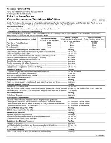
5.4 ClearancesThe unit clearance from a combustible surface may be 0". However, service clearance must take precedence. Aminimum of 24" in front of the unit for service clearance is required. Additional clearance on one side or top will berequired for electrical wiring connections. Consult all appropriate regulatory codes prior to determining final clearances. When installing this unit in an area that may become wet (such as crawl spaces), elevate the unit with asturdy, non-porous material. In installations that may lead to physical damage (i.e. a garage) it is advised to installa protective barrier to prevent such damage. Always install units such that a positive slope in condensate line (1/4"per foot) is allowed.5.5 Horizontal ApplicationsIf installed above a finished living space, a secondary drain pan (as required by many building codes), must beinstalled under the entire unit and its condensate drain line must be routed to a location such that the user will seethe condensate discharge.6Installation LocationNOTE: These air handlers are designed for indoor installationonly.The ARUF**14** and ASPT**14** product lines may be installed inone of the upflow, downflow, horizontal left or horizontal rightorientations as shown in Figures 2, 3, 4 and 5. The unit may beinstalled in upflow or horizontal left orientation as shipped (refer to specific sections for more information).Minor field modifications are necessary to convert to downflowor horizontal right as indicated in below sections.Side Drain Pan Removal: Refer to Figure 1, remove the two (2)screws that secure the drip shield support brackets to thecondensate collectors (front and back). Unsnap the side drainpan from vertical (bottom) drain pan using a screw driver or anysmall lever. The side drain pan and drip shield brackets may nowbe removed. The bottom left drain connection is the primarydrain for this application and condensate drain line must beattached to this drain connection. The bottom right drainconnection is for the secondary drain line (if used).6.1 Upflow InstallationNo field modifications are mandatory however to obtain maximum efficiency, the horizontal side drain pan & extension mustbe removed.DRIP SHIELD REMOVALFigure 16.2 Horizontal Left InstallationNo field modifications are permissible for this application.The bottom left drain connection is the primary drain for this application and condensate drain line must be attached tothis drain connection. The bottom right drain connection isfor the secondary drain line (if used).MODEL LIST FOR DOWNFLOW KIT6.3 DownflowDFK-BDFK-CDFK-DNo field modifications are mandatory however to obtainDOWNFLOW KITDOWNFLOW KITDOWNFLOW KITmaximum efficiency, the horizontal side drainpan & extenARUF25B14**ARUF37C14**ARUF37D14**sion must be removed.ARUF29B14**ARUF43C14**ARUF43D14**IMPORTANT NOTE: To prevent coil pan “sweating” in theARUF31B14**ARUF49C14**ARUF47D14**downflow application, a downflow kit (DFK) is availablethrough your local distributor. The DFK is not supplied withARUF49D14**the air handler and is required by the manufacturer on allARUF61D14**downflow installations. See Table 1 for the correct DFK andASPT61D14**follow the instructions provided for installation.DOWNFLOW KITTable 14
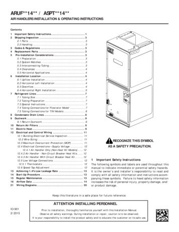
6.4 Horizontal Right InstallationSide drainpan extension must be removed for all models except : ARUF47D14**, ARUF61D14**, ASPT61D14**.Refer to Figure 6 and 7 for the location of the components referenced in the following steps.1. Before inverting the air handler, remove blower access panel and coil access panel. The coil access panel and tubingpanel may remain screwed together during this procedure. Remove and retain the seven (7) screws securing the coilaccess panel to the cabinet and the six (6) screws securing the blower access panel to the cabinet.2. Slide the coil assembly out from the cabinet. Use the drain pan to pull the assembly from the cabinet.NOTE: DO NOT USE MANIFOLDS OR FLOWRATOR TO PULL THE COIL ASSEMBLY OUT. FAILURE TO DO SO MAYRESULT IN BRAZE JOINT DAMAGE AND LEAKS.3. Removal of the center support is required on unitswith 21" wide cabinet. Remove and retain the two(2) screws that secure the center support to the cabinet. Remove the center support.4. Using the drain pan to hold the coil assembly, slidethe coil assembly back into the cabinet on thedownflow brackets as shown in Figure 8.5. Re-install the center support (if removed) using thetwo (2) screws removed in Step 4.6. Re-install the access panels removed in Step 1 asshown in Figure 9.7. The bottom right drain connection is the primary drainfor this application and condensate drain line mustbe attached to this drain connection. The bottom leftdrain connection is for the secondary drain line (ifused). Install the PVC plug that was removed fromthe side drain pan primary connection and install iton the vertical primary connection.NOTE: If removing only the coil access panel from theunit, the filter access panel must be removed first. Failure to do so will result in panel damage.UPFLOWDOWNFLOWFigure 2Figure 3HORIZONTAL LEFTHORIZONTAL RIGHTFigure 4Figure 55
BlowerAccessPanelSecondaryDrain ain Port forUpflow/Downflow ApplicationINTERNAL PART TERMINOLOGYEXTERNAL PART TERMINOLOGYFigure 6Figure 7Coil Slideson the downflow bracketIMPORTANT NOTE:Ensure coil slides on the rails along the groove provided on the drain pan sidewalls. Failure to do so will result in improper condensate drainage.COIL INSTALLATION FOR DOWNFLOWFigure 86ACCESS PANEL CONFIGURATION FOR DOWNFLOWOR HORIZONTAL RIGHTFigure 9
7 Refrigerant LinesNOTE: Refrigerant tubing must be routed to allow adequateaccess for servicing and maintenance of the unit.Do not install the air handler in a location that violatesthe instructions provided with the condenser. If the unitis located in an unconditioned area with high ambienttemperature and/or high humidity, the air handler maybe subject to nuisance sweating of the casing. On theseinstallations, a wrap of 2" fiberglass insulation with a vaporbarrier is recommended.This product is factory-shipped with R410A and drynitrogen mixture gas under pressure. Use appropriateservice tools and follow these instructions to preventinjury.A quenching cloth is strongly recommended to preventscorching or marring of the equipment finish whenbrazing close to the painted surfaces. Use brazingalloy of 5% minimum silver content.7.1 Tubing SizeFor the correct tubing size, follow the specificationfor the condenser/heat pump.CAUTIONApplying too much heat to any tube can melt the tube. Torchheat required to braze tubes of various sizes must beproportional to the size of the tube. Service personnel mustuse the appropriate heat level for the size of the tube beingbrazed.7.2 Tubing PreparationAll cut ends are to be round, burr free, and clean.Failure to follow this practice increases the chancesfor refrigerant leaks. The suction line is spun closedand requires tubing cutters to remove the closed end.NOTE: To prevent possible damage to the tubing joints, do not handle coil assembly with manifold or flowrator tubes.Always use clean gloves when handling coil assemblies.7.3 Special InstructionsUnits without a factory installed TXV come equipped with a flowrator piston for refrigerant expansion. For mostinstallations with matching applications, no change to the flowrator piston is required. However, in mix-matchedapplications, a flowrator piston change may be required. See the piston kit chart (provided in the literature packet)or consult your local distributor for details regarding mix-matched flowrator piston sizing. If the mix-match application requires a different flowrator piston size, change the flowrator piston in the flowrator body on the indoorcoil before installing the coil and use the procedure in section 8.4.NOTE: The use of a heat shield is strongly recommended when brazing to avoid burning the serial plate or the finishof the unit. Heat trap or wet rags must be used to protect heat sensitive components such as service valves and TXVvalves sensing bulb.7.4 Tubing Connections for Flowrator Model1. Loosen the 13/16 nut 1 TURN ONLY to allow high pressure tracergas to escape. No gas indicates a possible leak.SUCTION LINEWITH SPIN CLOSURE2. After the gas has been expelled, remove the nut and discard theblack or brass cap plastic seal.3. Remove the flowrator piston to verify it is the correct size forthe outdoor unit being installed and then replace the piston(changing size, if needed). See piston kit chart in the literaturekit for appropriate piston size.4. Remove the spin closure on the suction line using a tube cutterand deburr the tube.RUBBERGROMMETSUCTION SPUN END AND GROMMETFigure 105. Insert the suction line into the connection, slide the insulation and the rubber grommet at least 18" away from thebraze joint.6. Remove the tailpiece clamped to the exterior of the cabinet or in the literature kit packet and slide the 13/16 nutinto place.7. Braze tailpiece to the line set liquid tube and braze suction line connection. Quench all brazed joints with a damprag upon completion of brazing. Do not allow water to enter the inside of the tubing.7
8. AFTER THE TAILPIECE HAS COOLED, confirm position of the whiteTeflon seal and hand tighten the 13/16 nut.9. Torque the 13/16 nut to 7-25 ft-lbs. or tighten 1/6 turn.PLASTIC or BRASS CAP13/16” NUTTAILPIECEExcessive torque can cause orifices to stick. Use theproper torque settings when tightening orifices.PISTONWHITETEFLON SEALTAILPIECE JOINT7.5 Tubing Connections for TXV ModelsFigure 11TXV models come with factory installed TXV with the bulb preinstalled on the vapor tube.1. Remove refrigerant tubing panel or coil (lower) access panel.2. Remove access valve fitting cap and depress the valve stem in access fitting to release pressure. No pressure indicates possible leak.3. Replace the refrigerant tubing panel.4. Remove the spin closure on both the liquid and suction tubes using a tubing cutter.5. Insert liquid line set into liquid tube expansion and slide grommet about 18" away from braze joint.6. Insert suction line set into suction tube expansion and slide insulation and grommet about 18" away from braze joint.7. Braze joints. Quench all brazed joints with water or a wet rag upon completion of brazing.8Condensate Drain LinesThe coil drain pan has a primary and a secondary drain with 3/4" NPT female connections. The connectors required are 3/4" NPT male, either PVC or metal pipe, and should be hand tightened to a torque of no more than 37 in-lbs. to preventdamage to the drain pan connection. An insertion depth of approximately 3/8” to 1/2” (3-5 turns) should be expected atthis torque.1. Ensure drain pan hole is not obstructed.2. To prevent potential sweating and dripping on to finished space, it may be necessary to insulate the condensate drainline located inside the building. Use Armaflex or similar material.A secondary condensate drain connection has been provided for areas where the building codes require it. Pitch all drainlines a minimum of 1/4" per foot to provide free drainage. Provide required support to the drain line to prevent bowing.If the secondary drain line is required, run the line separatelyfrom the primary drain and end it where condensate dischargeCAUTIONcan be easily seen.NOTE: Water coming from secondary line means the coil priIf secondary drain is not installed, the secondarymary drain is plugged and needs immediate attention.access must be plugged.Insulate drain lines located inside the building or above a finished living space to prevent sweating. Install a condensatetrap to ensure proper drainage.NOTE: When units are installed above ceilings, or in other locationswhere damage from condensate overflow may occur, it is MANDATORYto install a field fabricated auxiliary drain pan under the coil cabinetenclosure.The installation must include a “P” style trap that is located as close asis practical to the evaporator coil. See Figure 12 for details of a typicalcondensate line “P” trap.NOTE: Trapped lines are required by many local codes. In the absenceof any prevailing local codes, please refer to the requirements listed inthe Uniform Mechanical Building Code.8DrainConnectionAir Handler2" MIN.POSITIVE LIQUIDSEAL REQUIREDAT TRAP3" MIN.Figure 12
A drain trap in a draw-through application prevents air from being drawn back through the drain line during fan operation thus preventing condensate from draining, and if connected to a sewer line to prevent sewer gases from being drawninto the airstream during blower operation.Field experience has shown condensate drain traps with an open vertical Tee between the air handler and the condensatedrain trap can improve condensate drainage in some applications, but may cause excessive air discharge out of the openTee. The manufacturer does not prohibit this type of drain but we also do not recommend it due to the resulting airleakage. Regardless of the condensate drain design used, it is the installer’s responsibility to ensure the condensate drainsystem is of sufficient design to ensure proper condensate removal from the coil drain pan.Use of a condensate removal pump is permitted when necessary. This condensate pump should have provisions forshutting off the control voltage should a blocked drain occur. A trap must be installed between the unit and the condensate pump.IMPORTANT NOTE: The evaporator coil is fabricated with oils that may dissolve styrofoam and certain types of plastics.Therefore, a removal pump or float switch must not contain any of these materials.Tip: Priming the “P” trap may avoid improper draining at the initial installation and at the beginning of the coolingseason.9 DuctworkThis air handler is designed for a complete supply and return ductwork system.Do not operate this product without all the ductworkattached.To ensure correct system performance, the ductwork is tobe sized to accommodate 350-450 CFM per ton of coolingwith the static pressure not to exceed 0.5" in w.c. Refer toACCA Manual D, Manual S and Manual RS for information on duct sizing and application. Flame retardant ductwork is tobe used and sealed to the unit in a manner that will prevent leakage.NOTE: A downflow application with electric heat must have an L-shaped sheet metal supply duct without any outlets orregisters located directly below the heater.9.1 Return DuctworkDO NOT LOCATE THE RETURN DUCTWORK IN AN AREA THAT CAN INTRODUCE TOXIC, OR OBJECTIONABLE FUMES/ODORS INTO THE DUCTWORK. The return ductwork is to be connected to the air handler bottom (upflow configuration).10Return Air FiltersEach installation must include a return air filter. This filtering may be performed at the air handler using the factoryfilter rails or externally such as a return air filter grille. When using the factory filter rails, a nominal 16x20x1”, 20x20x1”or 24x20x1” (actual dimension must be less than 23-½”x20”) filter can be installed on a B, C and D cabinet respectively(the cabinet size is the seventh letter of the model number).11Electric HeatRefer to the installation manual provided with the electric heat kit for the correct installation procedure. All electricheat must be field installed. If installing this option, the ONLY heat kits that are permitted to be used are the HKS series.Refer to the air handler unit’s Serial and Rating plate or the HKS specification sheets to determine the heat kits compatible with a given air handler. No other accessory heat kit besides the HKS series may be installed in these air handlers.The heating mode temperature rise is dependent upon the system airflow, the supply voltage, and the heat kit size (kW)selected. Use data provided in Tables 2, 3 and 4 to determine the temperature rise ( F).NOTE: For installations not indicated above the following formula is to be used:Where:TRkW3412VC* 1.08 CFM TR (kW x 3412) x (Voltage Correction) / (1.08XCFM)Temperature RiseHeater Kit Actual kWBtu per kW.96 (230 Supply Volts).92 (220 Supply Volts).87 (208 Supply Volts)ConstantMeasured Airflow*VC (Voltage Correction)9
NOTE: The Temperature Rise Tables can also be used to estimate the air handler airflow delivery. When using thesetables for this purpose set the room thermostat to maximum heat and allow the system to reach steady state conditions.Insert two thermometers, one in the return air and one in the supply air. The temperature rise is the supply air temperatureminus the room air temperature. Using the temperature rise calculated, CFM can be estimated from the TR formulaabove. See Technical Manual and/or Service Manual for more information.HEAT KIT NOMINAL kWCFMHEAT KIT NOMINAL 1421283535681015 19/20 0 SUPPLY VOLTAGE - TEMP. RISE FTable 2CFM15 19/20 25220/1/60 SUPPLY VOLTAGE - TEMP. RISE FTable 3HEAT KIT NOMINAL kW3568101519/20 03720004781113202733208/1/60 SUPPLY VOLTAGE - TEMP. RISE FTable 4M ODELHEATER KIT NIMUM CFM REQUIRED FOR HEATER KITSTable 510
12Electrical and Control WiringNominal InputMinimum VoltageMaximum Voltage208-240197253IMPORTANT: All routing of electrical wiring must be madethrough provided electrical knockouts. Do not cut, puncture or alter the cabinet for electrical wiring.ELECTRICAL VOLTAGETable 612.1 Building Electrical Service InspectionThis unit is designed for single-phase electrical supply only. DO NOT OPERATE ON A THREE-PHASE POWER SUPPLY.Measure the power supply to the unit. The supply voltage must be measured and be in agreement with the unitnameplate power requirements and within the range shown.12.2 Wire SizingWire size is important to the operation of your equipment. Use the following check list when selecting theappropriate wire size for your unit. Wire used must carry the Minimum Circuit Ampacity (MCA) listed on the unit’s Series and Rating Plate. Refer to the NEC (USA) or CSA (Canada) for wire sizing. The unit MCA for the air handler and the optional electric heat kit can be found on the unit Series and Rating Plate. Wire must be sized to allow no more than a 2% voltage drop from the building breaker/fuse panel tothe unit. Wires with different insulation temperature ratinghave varying ampacities - be sure to check the temperature rating used.Refer to the latest edition of the National ElectricCode or in Canada the Canadian Electric Code whendetermining the correct wire size.12.3 Maximum Overcurrent Protection (MOP)Every installation must include an NEC (USA) or CEC(Canada) approved overcurrent protection device.Also, check with local or state codes for any specialregional requirements.Protection can be in the form of fusing or HACR stylecircuit breakers. The Series and Rating Plate provides the maximum overcurrent device permissible.FIRE HAZARD!To avoid the risk of property damage, personal injuryor fire, use only copper conductors.HIGH VOLTAGE!Disconnect ALL power before servicing.Multiple power sources may be present.Failure to do so may cause property damage,personal injury or death.HIGH VOLTAGE!To avoid property damage, personal injury or deathdue to electrical shock, this unit MUST have anuninterrupted, unbroken electrical ground. Theelectrical ground circuit may consist of anappropriately sized elec
Before inverting the air handler, remove blower access panel and coil access panel. The coil access panel and tubing panel may remain screwed together during this procedure. Remove and retain the seven (7) screws securing the coil access panel to the cabinet and the six (6) screws securing the blower access panel to the cabinet. 2.