Transcription
SUPER SuperServer 5016I-MRSuperServer 5016I-MRFUSER’S MANUALRevision 1.0
The information in this User’s Manual has been carefully reviewed and is believed to be accurate.The vendor assumes no responsibility for any inaccuracies that may be contained in this document,makes no commitment to update or to keep current the information in this manual, or to notify anyperson or organization of the updates. Please Note: For the most up-to-date version of thismanual, please see our web site at www.supermicro.com.Super Micro Computer, Inc. ("Supermicro") reserves the right to make changes to the productdescribed in this manual at any time and without notice. This product, including software, if any,and documentation may not, in whole or in part, be copied, photocopied, reproduced, translated orreduced to any medium or machine without prior written consent.IN NO EVENT WILL SUPERMICRO BE LIABLE FOR DIRECT, INDIRECT, SPECIAL, INCIDENTAL,SPECULATIVE OR CONSEQUENTIAL DAMAGES ARISING FROM THE USE OR INABILITY TOUSE THIS PRODUCT OR DOCUMENTATION, EVEN IF ADVISED OF THE POSSIBILITY OFSUCH DAMAGES. IN PARTICULAR, SUPERMICRO SHALL NOT HAVE LIABILITY FOR ANYHARDWARE, SOFTWARE, OR DATA STORED OR USED WITH THE PRODUCT, INCLUDING THECOSTS OF REPAIRING, REPLACING, INTEGRATING, INSTALLING OR RECOVERING SUCHHARDWARE, SOFTWARE, OR DATA.Any disputes arising between manufacturer and customer shall be governed by the laws of SantaClara County in the State of California, USA. The State of California, County of Santa Clara shallbe the exclusive venue for the resolution of any such disputes. Super Micro's total liability forall claims will not exceed the price paid for the hardware product.This equipment has been tested and found to comply with the limits for a Class B digital devicepursuant to Part 15 of the FCC Rules. These limits are designed to provide reasonable protectionagainst harmful interference in a residential installation. This equipment generates, uses, and canradiate radio frequency energy and, if not installed and used in accordance with the manufacturer’sinstruction manual, may cause interference with radio communications. However, there is noguarantee that interference will not occur in a particular installation. If this equipment does causeharmful interference to radio or television reception, which can be determined by turning theequipment off and on, you are encouraged to try to correct the interference by one or more of thefollowing measures: Reorient or relocate the receiving antenna. Increase the separation betweenthe equipment and the receiver. Connect the equipment into an outlet on a circuit different fromthat to which the receiver is connected. Consult the dealer or an experienced radio/televisiontechnician for help.California Best Management Practices Regulations for Perchlorate Materials: This Perchloratewarning applies only to products containing CR (Manganese Dioxide) Lithium coin cells. “PerchlorateMaterial-special handling may apply. See NG: Handling of lead solder materials used in thisproduct may expose you to lead, a chemical known tothe State of California to cause birth defects and otherreproductive harm.Manual Revision 1.0Release Date: October 7, 2009Unless you request and receive written permission from Super Micro Computer, Inc., you maynot copy any part of this document.Information in this document is subject to change without notice. Other products and companiesreferred to herein are trademarks or registered trademarks of their respective companies or markholders.Copyright 2009 by Super Micro Computer, Inc.All rights reserved.Printed in the United States of America
PrefacePrefaceAbout This ManualThis manual is written for professional system integrators and PC technicians. Itprovides information for the installation and use of the SuperServer 5016I-MR/5016IMRF. Installation and maintenance shall be performed by experienced techniciansonly.The SuperServer 5016I-MR/5016I-MRF is a single processor system based on theSC512-200mini-tower chassis and the Super X8SIL/X8SIL-F motherboard.Manual OrganizationChapter 1: IntroductionThe first chapter provides a checklist of the main components included with thesystem and describes the main features of the Super X8SIL/X8SIL-F motherboardand the SC512-200chassis.Chapter 2: InstallationThis chapter describes the steps necessary to setup the system. If your server wasordered without the processor and memory components, this chapter will refer youto the appropriate sections of the manual for their installation.Chapter 3: System InterfaceRefer to this chapter for details on the system interface, which includes the functionsand information provided by the control panel on the chassis as well as other LEDslocated throughout the system.Chapter 4: System SafetyYou should thoroughly familiarize yourself with this chapter for a general overviewof safety precautions that should be followed when installing and servicing theSuperServer 5016I-MR/5016I-MRF.iii
SUPERSERVER 5016I-MR/5016I-MRF User's ManualChapter 5: Advanced Motherboard SetupChapter 5 provides detailed information on the X8SIL/X8SIL-F motherboard, including the locations and functions of connectors, headers and jumpers. Referto this chapter when adding or removing processors or main memory and whenreconfiguring the motherboard.Chapter 6: Advanced Chassis SetupRefer to Chapter 6 for detailed information on the SC512-200chassis. You shouldfollow the procedures given in this chapter when installing, removing or reconfiguring Serial ATA or peripheral drives and when replacing system power supply unitsand cooling fans.Chapter 7: BIOSThe BIOS chapter includes an introduction to BIOS and provides detailed information on running the CMOS Setup Utility.Appendix A: POST Error Beep CodesAppendix B: Installing WindowsAppendix C: System Specificationsiv
PrefaceNotesv
SUPERSERVER 5016I-MR/5016I-MRF User's ManualTable of ContentsChapter 1 Introduction1-1Overview . 1-11-2Motherboard Features . 1-2Processors . 1-2Memory . 1-2Serial ATA . 1-2PCI Expansion Slots . 1-2I/O Ports . 1-2Other Features . 1-21-3Server Chassis Features . 1-3System Power . 1-3Serial ATA Subsystem . 1-3Control Panel . 1-3Rear I/O Panel . 1-3Cooling System . 1-31-4Contacting Supermicro . 1-5Chapter 2 Server Installation2-1Overview . 2-12-2Unpacking the System . 2-12-3Preparing for Setup . 2-1Choosing a Setup Location . 2-1Rack Precautions . 2-2Server Precautions. 2-2Rack Mounting Considerations . 2-3Ambient Operating Temperature . 2-3Reduced Airflow . 2-3Mechanical Loading . 2-3Circuit Overloading . 2-3Reliable Ground . 2-32-4Installing the System into a Rack . 2-4Basic Installation Procedure . 2-4Installing with Rackmount Kit . 2-4Installing the Chassis Rails . 2-5Installing the Rack Rails . 2-5Installing the Server into the Rack . 2-6Installing the Server into a Telco Rack . 2-7vi
Table of Contents2-5Checking the Motherboard Setup . 2-82-6Checking the Drive Bay Setup . 2-10Chapter 3 System Interface3-1Overview . 3-13-2Control Panel Buttons . 3-1Reset . 3-1Power . 3-13-3Control Panel LEDs . 3-2Overheat. 3-2NIC2 . 3-2NIC1 . 3-2HDD. 3-2Power . 3-3Chapter 4 System Safety4-1Electrical Safety Precautions . 4-14-2General Safety Precautions . 4-24-3ESD Precautions . 4-34-4Operating Precautions . 4-4Chapter 5 Advanced Motherboard Setup5-1Handling the Motherboard . 5-1Precautions . 5-1Unpacking . 5-15-2Motherboard Installation . 5-25-3Connecting Cables . 5-2Connecting Data Cables . 5-2Connecting Power Cables . 5-3Connecting the Control Panel . 5-35-4I/O Ports . 5-45-5Processor and Heatsink Installation. 5-4Installing the LGA1156 Processor . 5-5Installing a Passive CPU Heatsink . 5-75-6Installing Memory . 5-9DIMM Installation . 5-9Memory Support . 5-9Memory Population Guidelines . 5-105-7Installing PCI Add-On Cards . 5-125-8Motherboard Details . 5-135-9Connector Definitions . 5-15vii
SUPERSERVER 5016I-MR/5016I-MRF User's ManualMain ATX Power Supply Connector . 5-15Processor Power Connector . 5-15Power Button . 5-15Reset Button . 5-15Overheat (OH)/Fan Fail . 5-16NIC1/NIC2 (LAN1/LAN2) . 5-16HDD LED. 5-16Power On LED . 5-16Chassis Intrusion . 5-17ATX PS/2 Keyboard and PS/2 Mouse Ports . 5-17Fan Headers. 5-17Onboard Speaker . 5-17Speaker . 5-18Serial Ports . 5-18Universal Serial Bus (USB) . 5-18LAN1/LAN2 (Ethernet Ports) . 5-18Onboard Power LED . 5-19Power Supply I2C Connector. 5-19T-SGPIO 0/1 Headers . 5-19Alarm Reset. 5-195-10Jumper Settings . 5-20Explanation of Jumpers . 5-20CMOS Clear . 5-20VGA Enable . 5-20LAN1/LAN2 Enable/Disable . 5-21PCI Slot SMB Enable . 5-21USB Wake-Up . 5-21BMC Jumper . 5-215-11Onboard Indicators. 5-22LAN1/2 LEDs. 5-22IPMI Dedicated LAN LEDs . 5-22Onboard Power LED. 5-22IPMI Heartbeat LED . 5-225-12SATA and Floppy Drive Connections . 5-23SATA Ports . 5-23Floppy Connector . 5-235-13Installing Software . 5-24Supero Doctor III . 5-25viii
Table of ContentsChapter 6 Advanced Chassis Setup6-1Static-Sensitive Devices . 6-1Precautions . 6-1Unpacking . 6-16-2Control Panel . 6-26-3System Fans . 6-3System Fan Failure . 6-36-4Drive Bay Installation/Removal . 6-4Accessing the Drive Bays . 6-46-5Power Supply . 6-6Power Supply Failure . 6-6Chapter 7 BIOS7-1Introduction. 7-1Starting BIOS Setup Utility . 7-1How To Change the Configuration Data . 7-1How to Start the Setup Utility . 7-27-2Main Setup . 7-27-3Advanced Setup Configurations. 7-47-4Security Settings . 7-207-5Boot Settings . 7-217-6Exit Options . 7-22Appendix A POST Error Beep CodesAppendix B Installing WindowsAppendix C System Specifications
SUPERSERVER 5016I-MR/5016I-MRF User's ManualNotes
Chapter 1: IntroductionChapter 1Introduction1-1OverviewThe SuperServer 5016I-MR/5016I-MRF is 1U server comprised of two main subsystems: the SC512-200 mini 1U chassis and the X8SIL/X8SIL-F motherboard. Pleaserefer to our web site for information on operating systems that have been certifiedfor use with the SuperServer 5016I-MR/5016I-MRF (www.supermicro.com).In addition to the motherboard and chassis, various hardware components havebeen included with the SuperServer 5016I-MR/5016I-MRF, as listed below: One cooling fan (FAN-0059L4) One passive heatsink (SNK-P0046P) One riser card (CSE-RR1U-E8) SATA AccessoriesOne SATA cable (CBL-0061L)One SuperServer 5016I-MR/5016I-MRF User's ManualOptional One slim DVD-ROM drive (DVM-LITE-DVDRW-SBT or DVM-PNSC-DVDSBT) One DVD-ROM drive cable (CBL-0341L) One DVD USB adapter (CDM-USATA-G)1-1
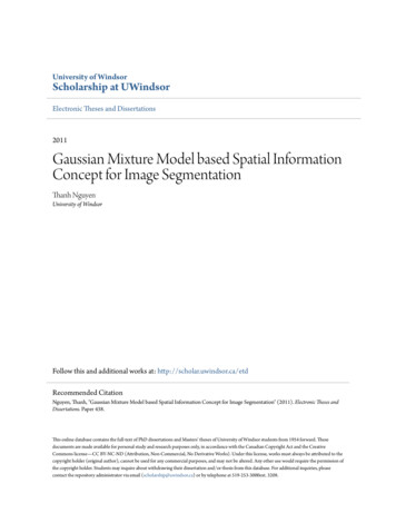
SUPERSERVER 5016I-MR/5016I-MRF User's Manual1-2Motherboard FeaturesAt the heart of the SuperServer 5016I-MR/5016I-MRF lies the X8SIL/X8SIL-F, asingle processor motherboard based on the Intel 3400 chipset. Below are themain features of the X8SIL/X8SIL-F. (See Figure 1-1 for a block diagram of thechipset).ProcessorsThe X8SIL/X8SIL-F supports a single Intel 3400 series processor in an LGA1156socket. Please refer to the motherboard description page on our web site for acomplete listing of supported processors (www.supermicro.com).MemoryThe X8SIL/X8SIL-F has four DIMM slots that can support up to 16 GB of UDIMM(unbuffered DIMMs) or up to 32 GB or RDIMM (registered DIMMs) DDR31333/1066/800 memory. Dual-channel configurations are supported. Memory modules of the same size and speed should be used. See Chapter 5 for details.Serial ATAA SATA controller is integrated into the chipset to provide a 3 Gb/s Serial ATA subsystem, which is RAID 0, 1, 10 and (Windows only) 5 capable. The SATA drivesare hot-swappable units. The X8SIL/X8SIL-F has four SATA ports.PCI Expansion SlotsThe X8SIL/X8SIL-F has two PCI-Express 2.0 x8 slots, one PCI-Express 2.0 x4 (ina x8 slot) and one 32-bit PCI 33 MHz slot.I/O PortsThe color-coded I/O ports include a COM port, two USB 2.0 ports, PS/2 mouseand keyboard ports and two Gb Ethernet ports. An IPMI LAN port is also includedon the X8SIL-F.Other FeaturesOther onboard features that promote system health include onboard voltage monitors, a chassis intrusion header, 3-phase switching voltage regulators, chassis andCPU overheat sensors, Thermal Monitor 2 (TM2) support and a BIOS flash upgradeutility.1-2
Chapter 1: Introduction1-3Server Chassis FeaturesThe SC512-200 is a mini 1U rackmount server platform configuration. The followingis a general outline of the main features of the SC512-200 chassis.System PowerWhen configured as a SuperServer 5016I-MR/5016I-MRF, the SC512-200 chassisincludes a single 200W power supply.Serial ATA SubsystemThe SC512-200 chassis was designed to support one internal 3.5" Serial ATA harddrive. This Serial ATA drive is not hot-swappable; power must be removed from thesystem before installing or replacing.Control PanelThe control panel on the SC512-200 provides important system monitoring andcontrol information. LEDs indicate power on, network activity, hard disk drive activity,overheat warning and fan failure. A main power button and a system reset button arealso included. Below the control panel are two USB ports for front side access.Rear I/O PanelThe rear I/O panel on the SC512-200 provides one motherboard expansion slot, oneCOM port (another is internal), two USB ports, PS/2 mouse and keyboard ports, agraphics port and two Gb Ethernet ports.Cooling SystemThe SC512-200 chassis has an innovative cooling design that features one 10-cmblower-type system cooling fan. The blower fan plugs into a chassis fan headeron the motherboard and an air shroud channels the airflow to efficiently cool theprocessor area.A fan speed control setting in BIOS allows fan speed to be determined by systemtemperature [the recommended setting is 3-pn (Server)].1-3
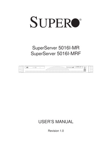
SUPERSERVER 5016I-MR/5016I-MRF User's ManualFigure 1-1. Intel 3400 Chipset:System Block DiagramNote: This is a general block diagram. Please see Chapter 5 for details.PCIe x8 SLOTPCIe2.0 x8PCIe x8 SLOTPCIe2.0 x85.0Gb5.0GbXeon 3400SeriesVID[0-7]1 PCI 32 SLOT2.5GbpsPCI 32IBexPeakCK505Rev1.0FLASHSPI 16Mb300MB/sPCHGLAN182574LRJ45PCIe TPM1.2HERMON on)RMIISPIP/S2DIMM1(Far)DIMM2PCIe x12.5GbpsUSB2.0LPC5/7 USB PORTSSATA-IIDIMM1(Far)DIMM22.5Gbx4 DMIPCIe x4Intel 3400/34204/6 SATA PORTSDDR3 (CHB)1333/1066MHzVRM 11.1MISC VRsPCIe x8 SLOTDDR3 (CHA)1333/1066MHzW83627DHGLPC I/O1-4VGAPORT4 UDIMM4 RDIMM(4 Quad rankRDIMM run on800MHz)
Chapter 1: Introduction1-4Contacting SupermicroHeadquartersAddress:Super Micro Computer, Inc.980 Rock Ave.San Jose, CA 95131 U.S.A.Tel: 1 (408) 503-8000Fax: 1 (408) 503-8008Email:marketing@supermicro.com (General Information)support@supermicro.com (Technical Support)Web Site:www.supermicro.comEuropeAddress:Super Micro Computer B.V.Het Sterrenbeeld 28, 5215 ML's-Hertogenbosch, The NetherlandsTel: 31 (0) 73-6400390Fax: 31 (0) 73-6416525Email:sales@supermicro.nl (General Information)support@supermicro.nl (Technical Support)rma@supermicro.nl (Customer Support)Asia-PacificAddress:Super Micro Computer, Inc.4F, No. 232-1, Liancheng Rd.Chung-Ho 235, Taipei CountyTaiwan, R.O.C.Tel: 886-(2) 8226-3990Fax: 886-(2) 8226-3991Web Site:www.supermicro.com.twTechnical 228-1366, ext.132 or 1391-5
SUPERSERVER 5016I-MR/5016I-MRF User's ManualNotes1-6
Chapter 2: Server InstallationChapter 2Server Installation2-1OverviewThis chapter provides a quick setup checklist to get your SuperServer 5016IMR/5016I-MRF up and running. Following the steps in the order given shouldenable you to have the system operational within a minimal amount of time. Thisquick setup assumes that your server system has come to you with the processor and memory preinstalled. If your system is not already fully integrated with amotherboard, processor, system memory etc., please turn to the chapter or sectionnoted in each step for details on installing specific components.2-2Unpacking the SystemYou should inspect the box the SuperServer 5016I-MR/5016I-MRF was shippedin and note if it was damaged in any way. If the server itself shows damage, youshould file a damage claim with the carrier who delivered it.Decide on a suitable location for the rack unit that will hold the server. It shouldbe situated in a clean, dust-free area that is well ventilated. Avoid areas whereheat, electrical noise and electromagnetic fields are generated. You will also needit placed near a grounded power outlet. Read the Rack and Server Precautionsin the next section.2-3Preparing for SetupThe SuperServer 5016I-MR/5016I-MRF does not ship with a rack rail hardwarepackage as the system can be rack mounted without the use of rails. An optionalrack rail package is available if you wish to order from Supermicro. Follow the stepsin the order given to complete the installation process in a minimal amount of time.Please read this section in its entirety before you begin the installation procedureoutlined in the sections that follow.Choosing a Setup Location Leave enough clearance in front of the rack to enable you to open the front doorcompletely ( 25 inches) and approximately 30 inches of clearance in the backof the rack to allow for sufficient airflow and ease in servicing.This product is for2-1
SUPERSERVER 5016I-MR/5016I-MRF User's Manualinstallation only in a Restricted Access Location (dedicated equipment rooms,service closets and the like). This product is not suitable for use with visual display work place devicesacccording to §2 of the the German Ordinance for Work with Visual DisplayUnits.!Warnings and Precautions!!Rack Precautions Ensure that the leveling jacks on the bottom of the rack are fully extended tothe floor with the full weight of the rack resting on them. In single rack installation, stabilizers should be attached to the rack. In multiplerack installations, the racks should be coupled together. Always make sure the rack is stable before extending a component from therack. You should extend only one component at a time - extending two or more simultaneously may cause the rack to become unstable.Server Precautions Review the electrical and general safety precautions in Chapter 4.Determine the placement of each component in the rack before you install therails.Install the heaviest server components on the bottom of the rack first, and thenwork up. Use a regulating uninterruptible power supply (UPS) to protect the server frompower surges, voltage spikes and to keep your system operating in case of apower failure. Allow the hot plug SATA drives and power supply modules to cool before touching them. Always keep the rack's front door and all panels and components on the serversclosed when not servicing to maintain proper cooling.2-2
Chapter 2: Server InstallationRack Mounting ConsiderationsAmbient Operating TemperatureIf installed in a closed or multi-unit rack assembly, the ambient operating temperature of the rack environment may be greater than the ambient temperature of theroom. Therefore, consideration should be given to installing the equipment in anenvironment compatible with the manufacturer’s maximum rated ambient temperature (Tmra).Reduced AirflowEquipment should be mounted into a rack so that the amount of airflow requiredfor safe operation is not compromised.Mechanical Loading
manual, please see our web site at www.supermicro.com. Super Micro Computer, Inc. ("Supermicro") reserves the right to make changes to the product described in this manual at any time and without notice. This product, including software, if any, . Supero Doctor III . 5-25 SUPERSERVER 5016I-MR/5016I-MRF User's Manual. Chapter 6 Advanced .