Transcription
Lighting Surge Protection ModulesDesign and Installation Guide
LEDLighting SurgeProtection ModulesDesign and InstallationGuideTable of ContentsPageIntroduction3Indirect Lightning-Induced Surge3Regional Differences in Lightning Frequency6Components That Protect Against Induced Surge Events8Modular Solution vs. a Solution Embedded into thePower Supply Unit9Thermally Protected MOV for SPD Safety9Over-voltage Testing in UL 1449 and IEC 61643-1110Coordination between the SPD and the Power Supply Unitto Reduce “Surge Let-through”16Power Supply Unit Design Considerations (Fuse,Equivalent Resistance, TVS Diode)18Wiring Guide20Installation Guide22Legal Disclaimers23 2014 Littelfuse, Inc.Specifications descriptions and illustrative material in this literature are as accurate as known at the time of publication,but are subject to changes without notice. Visit littelfuse.com for more information.
LED Lighting Surge Protection ModulesDesign and Installation GuideIntroduction and Indirect Lightning-Induced SurgeIntroductionLED lighting is increasingly replacing legacy light sources (mercury vapor, metal halideand sodium vapor) in outdoor applications as a result of technological revolutions in LEDefficiency (higher lumens per watt), secondary optics (better lenses/reflectors), and greaterthermal dissipation. However, the initial cost of installing outdoor LED lighting can besubstantial; this cost is justified and payback is established based on the lower wattagedemand, lower maintenance cost, and longer lifetime it offers. In order to protect outdoorLED lighting from failing within an investment payback period of about five years, the lightingmust offer high durability and reliability. Transient surge events in AC power lines, which candamage lighting fixtures, represent a significant threat to outdoor LED lighting installations.Indirect Lightning-Induced SurgeWhen nearby electrical equipment is switched on or off, over-voltage transient surges canoccur in AC power lines. Nearby lightning strikes can also generate transient surges in ACpower lines (Figure 1), especially in outdoor environments.Figure 1. Transient over-voltage on an AC power line resulting from an indirect lightning strike.Lightning strikes are electrostatic discharges, which usually travel from cloud to cloudor cloud to the ground, with magnitudes of millions of volts (Figure 2). Indirect lightningstrikes, even those that occur several miles away, can induce magnetic fields that generatesurges of thousands of volts through current-carrying copper wires, such as the overheadand underground cables that power streetlights. These indirect strikes, which producelevels of energy with magnitudes greater than 1000A 2s, can be characterized with specificwaveforms. 2014 Littelfuse LED Lighting SPD Modules Design and Installation Guide3www.littelfuse.com
LED Lighting Surge Protection ModulesDesign and Installation GuideIndirect Lightning-Induced Surge re 2. Indirect lightning strikes can induce magnetic fields in overhead and underground powerlines that produce over-voltage transient surges.The surges produced by electrical storms can adversely affect outdoor LED lightinginstallations. The luminaire (the combination of a module or a light engine with control gear toform a lighting system) is susceptible to damage both in the differential and common modes: Differential Mode – High voltage/current transients between the Line-Neutral (L-N) orLine-Line (L-L) terminals of the luminaire could damage components in the power supplyunit or the LED module board. Common Mode – High voltage/current transients between the L-G (earth) or N-G (earth)terminals of the luminaire could damage safety insulation in the power supply unit or LEDmodule board, including the LED to heat sink insulation.Based on site surveys and statistics on years of lightning strike data in the United States, theIEEE (Institute of Electrical and Electronics Engineers) recommends test criteria for inducedsurge waveforms and energy levels for indoor/outdoor locations (Category A/B/C). The IEEErecommendations were then referred to by ANSI (the American National Standards Institute)and the DOE (Department of Energy) when testing standards were established in theUnited States. 2014 Littelfuse LED Lighting SPD Modules Design and Installation Guide4www.littelfuse.com
LED Lighting Surge Protection ModulesDesign and Installation GuideIndirect Lightning-Induced Surge (continued)ServiceEquipmentCategory A: Partsof the installation atsome distance from theservice entranceServiceEntranceCategory B: BetweenCategory A andCategory CCategory C: Externalpart of structure,extending some distanceinto the ory ALocationCategory BOutbuildingServiceEntranceUnderground ServiceLocationCategory CFigure 3. Location categories defined by IEEE standards for surge environments.The U.S. Department of Energy (DOE) Municipal Solid State Street Lighting Consortium(MSSLC) has developed a model specification that ensures roadway LED luminaires andparking lot and garage LED lighting exhibit adequate surge immunity to withstand indirectlightning energy. Cities, municipalities, and utilities in North America are adopting this modelspecification in their Requests for Quotes (RFQs) for lighting retrofit and replacementprojects. The DOE specification details performance and surge suppression requirements asshown in Table 1 for two levels, Location Category C Low and C High.Table 1. 1.2/55μs - 8/20μs Combination Wave Specification*This is a MINIMUM requirement.Note that for most combinationwave generators, which havea source impedance of 2W, thegenerator charging voltage willneed to be raised above thespecified level (to somewhere inthe vicinity of 20kV) to obtain thespecified current peak.ParameterTest Level/ Configuration1.2/50µs Open Circuit Voltage PeakLow: 6 kV. High: 10kV*8/20µs Short Circuit Current PeakLow: 3 kA. High: 10kACoupling ModesL1 toPE, L2 to PE, L1 to 72Polarity and Phase AnglePositive at 90 and Negative at 270 Test Strikes5 for each Coupling Mode and Polarity/Phase AnglecombinationTime Between Strikes1 minuteTotal Number of Strikes 5 strikes 3 coupling modes 2 polarity/phase angles 30 totaI strikes 2014 Littelfuse LED Lighting SPD Modules Design and Installation Guide5www.littelfuse.com
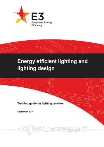
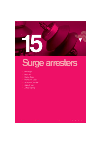
LED Lighting Surge Protection ModulesDesign and Installation GuideRegional Differences in Lightning FrequencyThe DOE test waveform used to evaluate surge immunity of luminaires used in outdoorlighting (Figure 4) is a combination 1.2x50μs open circuit voltage and 8x20μs short circuitcurrent waveform. To perform this test, the specified peak current is calibrated on the surgegenerator by shorting the output to ground prior to connection to the luminaire.1.01.0Front Time - 8 µs0.80.60.6I(t)/IpV(t)/VpFront Time - 1.2 µs0.8Duration - 50 µs0.40.20Duration - 20 µs0.40.20204060800100Time (µs)01020304050Time (µs)Figure 4. Open-circuit voltage and short-circuit current waveforms to represent transient surgeson an AC power line. Vp and Ip represent the peak voltage and current, respectively.Regional Differences in Lightning FrequencyLightning frequency may refer to the number of lightning strikes in a region during a particularperiod or to the probability quotient of lightning strike frequency.Satellite-based Lightning Imaging Sensor (LIS) observations are used to study lightningactivity in different regions of the world. This research has shown clear differences in bothflash frequency and optical radiance in different regions. The flash activity in different regionsshows a clear difference, corresponding to the local climate, topography, and environmentconditions.IEEE studied the effect of indirect lightning on outdoor lighting and recommended transientsurge testing levels (3kA and 10kA) for the United States. For other regions for which lightingsurvey data and regional regulations aren’t available, NASA’s research on worldwide lightningstrike frequency (Figure 5) may be useful as a reference for comparison. Central and SouthAmerica, Africa, Southern and Southeastern Asia have lightning strike frequencies similarto Florida in the United States, so an equivalent surge immunity level (10kA) is suggested.For regions with fewer lightning strikes, such as Europe, Eastern Asia, and Australia, a lowersurge immunity level could be considered at 3kA. 2014 Littelfuse LED Lighting SPD Modules Design and Installation Guide6www.littelfuse.com
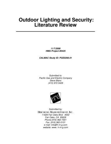
LED Lighting Surge Protection ModulesDesign and Installation GuideRegional Differences in Lightning Frequency (continued)Figure 5. This map of worldwide lightning frequency (courtesy of NASA Global HydrologyResource Center) depicts the number of lightning flashes/km2/year for various regions.Incorporating a robust surge suppression circuit in an outdoor LED luminaire can eliminatedamage caused by surge energy, enhancing reliability, minimizing maintenance, andextending the useful life of the lighting installation (Figure 6). A surge protection subassemblythat can suppress excessive surges to lower voltage levels is an optimal way to protect theLED luminaire investment.Figure 6. LED street light protection scheme. 2014 Littelfuse LED Lighting SPD Modules Design and Installation Guide7www.littelfuse.com
LED Lighting Surge Protection ModulesDesign and Installation GuideComponents That Protect Against Induced Surge EventsComponents That Protect Against Induced Surge EventsProtecting outdoor LED lighting from lightning induced surges requires diverting high voltage/current transient interference away from sensitive electronics in the lighting fixture. A varietyof surge protective devices (SPDs) are used in outdoor LED lighting to suppress surge energyand minimize surge impact. These include metal-oxide varistors (MOVs), gas discharge tubes(GDTs), and transient voltage suppression (TVS) diodes (Figure 7). These components aredesigned to remain at “standby” in the circuit under normal operation. When an abnormalhigh-voltage transient occurs, they activate to absorb the transient energy, then return tostandby mode.Original transientVoltageGDTMOVTVS diodeTimeFigure 7. How GDTs, MOVs, and TVS diodes respond to a transient surge to suppress thethreat it poses.Of the technologies outlined in Table 2, MOVs are preferred and widely used for surgeprotection in power distribution panels due to their high surge energy-handling capabilityand fast response to transient voltage. Therefore, MOVs are also suitable for use as surgeprotection devices in outdoor LED lighting applications.TechnologyGDTMOVTVS DiodeHigh(1kA 100kA)High(0.1kA 100kA)Medium(0.1kA 15kA)Slow (ns)Fast (ns)Faster (ps)HighMediumLowLeakage CurrentNoLowLowFollow-on CurrentYesNoNoFatigueYesYesNoSurge Handling Capability(8/20µs)Response TimeMax. Clamping VoltageTable 2. Surge protection device technologies 2014 Littelfuse LED Lighting SPD Modules Design and Installation Guide8www.littelfuse.com
LED Lighting Surge Protection ModulesDesign and Installation GuideModular Solution vs. a Solution Embedded and Thermally Protected MOV for SPD SafetyModular Solution vs. a Solution Embedded into thePower Supply UnitOutdoor luminaires are easily affected by transient surges inductively coupled into powerlines from lightning strikes. IEEE C62.41.2 -2002 categorizes two different exposure levelsfor outdoor locations (Category C Low and C High) with different suggested surge levels.Similarly, some regions or countries may have different surge level requirements due todifferent lightning strike density in the area. Although some LED luminaires feature surgeprotection devices embedded in the power supply unit, Littelfuse recommends that thesurge protection circuit be provided as an independent module that’s separate from theluminaire power supply; in this way, the same luminaire can be easily marketed globally byattaching different surge protection modules to meet differing surge level requirements.MOVs are widely used in surge protection circuits for their fast response times, high surgeenergy handling, compact size, and cost-effectiveness. However, after MOVs absorb acertain number of surge strikes, they will begin to degrade and can no longer provide thesame protection as new ones. Having a separate surge protection module allows for easyreplacement when the original module reaches its end of life.Thermally Protected MOV for SPD SafetyMOV technology is not only inexpensive but also highly effective for suppressing transientsin power supplies and many other applications, such as the SPD modules that are oftenplaced upstream from an LED driver.MOVs tend to degrade gradually after a large surge or multiple small surges. This degradationleads to increasing MOV leakage current; in turn, this raises the MOV’s temperature, evenunder normal conditions like 120Vac/240Vac operating voltage. A thermal disconnectadjacent to the MOV (Figure 8) can be used to sense the increase in MOV temperaturewhile it continues to degrade to its end-of-life condition; at this point, the thermal disconnectwill open the circuit, removing the degraded MOV from the circuit and preventing it fromfailing catastrophically.Figure 8. A thermal disconnect can open the circuit, preventing a catastrophic failure of adegraded MOV. 2014 Littelfuse LED Lighting SPD Modules Design and Installation Guide9www.littelfuse.com
LED Lighting Surge Protection ModulesDesign and Installation GuideOver-voltage Testing in UL 1449 and IEC 61643-11MOVs are designed to clamp fast over-voltage transients within microseconds. However, inaddition to short duration transients, MOVs inside SPD modules can experience temporaryover-voltage conditions caused by loss of neutral or by incorrect wiring during installation(Figure 9). These conditions can severely stress an MOV, causing it to go into thermalrunaway; in turn, this will result in overheating, smoke, and the potential for fire. UL 1449and IEC 61643-11, the safety standards for SPDs, define specific abnormal conditions underwhich devices must be tested to ensure SPD safety. Robust SPD module designs includethermal disconnects to protect the MOVs from thermal runaway.Figure 9. Temporary over-voltage conditions can severely stress MOVs, leading tothermal runaway.Over-voltage Testing in UL 1449 and IEC 61643-11UL 1449 Abnormal Overvoltage TestIn AC line applications, the loss of a Neutral-Ground connection may occur in such a way thatthere exists a risk that a sustained over-voltage may be applied to an MOV that is rated fora much lower continuous voltage. In an unlimited current condition, the MOV will first fail toa low impedance (few Ohms) state, but due to the high amount of energy available, it mostoften ruptures instantaneously. If, however, there are loads connected to the AC line thatlimit current flow, the MOV can overheat and potentially cause the SPD device to overheatresulting in smoke, out-gassing and eventually fire. 2014 Littelfuse LED Lighting SPD Modules Design and Installation Guide10www.littelfuse.com
LED Lighting Surge Protection ModulesDesign and Installation GuideOver-voltage Testing in UL 1449 and IEC 61643-11 (continued)120 VMOV ratedfor 150 V rmscontinuousvoltage120 VLoadFigure 10. Loss of Neutral-Ground connection in a standard U.S. split-phase powerdistribution system.For example, in a standard U.S. 120V AC Line application, two 120V AC power lines (180 out of phase) are commonly fed from a center-tapped 240V transformer. See Figure 10.Let’s assume a 150V-rated MOV is present in the top 120V circuit, and some load existson the bottom 120V circuit. Both the MOV and load share the center tap, which is theNeutral-Ground connection. If a break occurs on the center tap (X—X), then the load in thebottom phase acts as a current limiter, and the line fuse may not clear. In this scenario, the150V rated MOV is subjected to 240V at a limited current, potentially resulting in thermalrunaway for the MOV. Table 44.1 in UL 1449 4th Edition defines the test voltage that shouldbe applied to various SPD devices depending on the designer’s desired device rating.(See Table 3.)a. For device ratings not specifiedin the table, the test voltage shallbe the maximum phase voltage (ifavailable) or twice the conductorpair voltage rating up to 1000V max.b. Abnormal Overvoltage Tests arenot required to be conducted on600V delta rated units, but shortcircuit testing shall be performed.c. The Short Circuit and IntermediateCurrent tests are performed at thefull phase voltage.Nominal �120V / 220–240V120 / 208V220 / 380V230 / 400V220–240 / 380–415240 / 415V254–270 / 440–480V346 / 600V400 / 690V120 / 240V240 / WYEHigh leg deltaHigh leg deltaDeltaTest Voltage aTwice Rated Voltage240380400480600690Twice Rated Voltage up toMax. 00VDeltabTable 3. Test voltage selection table (reproduced from Table 44.1 in UL 1449 4th Edition). 2014 Littelfuse LED Lighting SPD Modules Design and Installation Guide11www.littelfuse.com
LED Lighting Surge Protection ModulesDesign and Installation GuideOver-voltage Testing in UL 1449 and IEC 61643-11 (continued)IEC 61643-11 Temporary Overvoltage (TOV) TestCompared to surge transients, which are short-duration (microseconds) over-voltagedisturbances in AC power lines, temporary over-voltages (TOVs) are longer-duration(milliseconds to minutes long) abnormal high voltages affecting the SPD module. TOVscan lead to short-circuited SPD modules and thermal runaway, potentially resulting in acatastrophic fire or explosion of the SPD.Several things can cause TOVs to occur in AC power lines. IEC 61643-11 includes a TOVtest in the standard to simulate these possible causes and verify SPD module safety. TOVsare caused by short-circuit faults in the power distribution network and by faults in the lowvoltage system and the high/medium voltage system. TOV caused by faults in the low voltage system–– Line-to-Ground Fault. A single line-to-ground fault at one phase shifts theground potential at the fault location and generates 1.73 ( 3) over-voltage atanother phase line-to-ground in the worst case. The over-voltage conditioncontinues until an over-current device activates to clear the line-to-ground fault,which usually happens in less than five seconds.(A) Normal Conditions(B) Fault ConditionsCCLine-to-GroundOver-voltageNeutral GroundBABA GroundFigure 11. Line-to-ground fault in 3-phase electric power system. 2014 Littelfuse LED Lighting SPD Modules Design and Installation Guide12www.littelfuse.com
LED Lighting Surge Protection ModulesDesign and Installation GuideOver-voltage Testing in UL 1449 and IEC 61643-11 (continued)–– Loss of Secondary Neutral. A broken neutral shifts its potential away and maycause a 1.73 ( 3) over-voltage at Line-to-Neutral in the worst case.(A) Normal(B) Lost of neutralL1L1U0U0NNU0N1L3L2L3L2Figure 12. Lost-of-neutral in 3-phase electric power system TOV caused by faults in the high/medium voltage systemWhen a distribution transformer (for example, 10kV to 380V, as shown in Figure 13) hasa short-circuit fault at the high-voltage side (10kV) Line-to-Ground, it generates a highfault current (Id 300A, 200ms duration) through grounding resistor Re (4Ω), which inturn elevates the Neutral potential (Ue 1200V) at the low-voltage side. The TOV test thusintends to simulate a ground fault at the high-voltage system by injecting 1200V into N-G atthe SPD module in the low-voltage system.100kV10kV380VId 300AUe 1200VRe (4-ohm) grounding resistorFigure 13. Line-to-ground fault in high/medium voltage transformerTemporary over-voltages affect SPDs when a short-circuit fault happens in a power network.It is important for SPDs to meet both the UL 1449 and IEC 61643-11 standards to ensuretheir safety and reliability. The addition of thermally protected MOVs in SPDs not onlysuppresses transient voltages but also ensures their own safety against overheating andcatching fire. 2014 Littelfuse LED Lighting SPD Modules Design and Installation Guide13www.littelfuse.com
LED Lighting Surge Protection ModulesDesign and Installation GuideOver-voltage Testing in UL 1449 and IEC 61643-11 (continued)End-of-Life/Replacement Indication for SPDsWhen an MOV becomes overheated due to temporary over-voltage or excessive leakagecurrent, a thermal disconnect may be used to help remove it from the AC circuit. However,with the MOV removed from the circuit, the SPD module no longer provides surgesuppression. Therefore, it’s important to supply proper indication so that maintenancepersonnel will know the SPD is not working and requires replacement.Luminaire designers can choose from two main types of SPD module configurations basedon their maintenance and warranty strategies. Those are parallel- and series-connected surgeprotection subassemblies. Parallel Connection – The SPD module is connected in parallel with the load. An SPDmodule that has reached end-of-life is disconnected from the power source while leavingthe AC/DC power supply unit energized. The lighting still remains operational, but theprotection against the next surge to which the power supply unit and LED module areexposed is lost. In a parallel-connected SPD module, replacement indication can be addedthrough the use of a small LED that indicates the SPD module status to the maintenancetechnician. Options for a green LED indicating an online SPD module or a red LEDindicating an offline SPD module are available. Or, rather than an LED indication at eachlighting fixture, the need for SPD module replacement could be indicated remotely to alight management center with SPD module end-of-life indication wires connected to anetworked smart lighting system. Series Connection – The SPD module is connected in series with the load, wherethe end-of-life SPD module is disconnected from the power source, which turns thelight off. The loss of power to the luminaire serves as indication for a maintenance call.The disconnected SPD module not only turns the lighting off to indicate the need forreplacement but also isolates the AC/DC power supply unit from future surge strikes.General preference for this configuration is growing rapidly because the luminaireinvestment remains protected while the SPD module is awaiting replacement. It’s far lessexpensive to replace a series-connected SPD module than the whole luminaire as in thecase of a parallel-connected SPD module.(b)(a)Figure 14. An SPD module that’s parallel-connected to a luminaire (a) and an SPD module that’sseries-connected to a luminaire (b). 2014 Littelfuse LED Lighting SPD Modules Design and Installation Guide14www.littelfuse.com
LED Lighting Surge Protection ModulesDesignandInstallationGuideLLL AC/DCNPowerOver-voltage Testing in UL 1449 andL IECor61643-11(continued)NN/G-SupplyGLED ModuleLSP10 Wiring Guide, Parallel Connection with End-of-Life IndicationParallel ConnectionApply series-connected models of LSP10 Series thermally protected varistor modules (asSPDindicated by an S suffix in the part number)as parallel connections in the lighting fixture. ThisLSP10xxxPturns the output wires of the series-connected SPD modules into end-of-life indication wires.LLorN/GLLNN AC/DCPower-SupplyGParallel ConnectionWith LED indicating SPD status- ON (green): SPD is online- OFF: SPD needs replacementLED ModuleLED normally onSPDLSP10xxxSRFigure 15. Connect a current limiting resistor and a green LED to form an external indicator ofmodule status. When the green LED is on, the module is working normally. When the greenLED is off, the module is disconnected from the power circuit, so it is no longer providing surgeprotection to downstream devices. It must be replaced with a new one.LSP05 Wiring Guide, Parallel Connection with End-of-Life IndicationLLorN/GLLNNAC/DCPowerSupplyGParallel ConnectionWith LED indicating SPD status- ON (green): SPD is online- OFF: SPD needs replacementLLorN/GSPD-LED ModuleR1R2R3NCLED normally onLSP05xxxPMLLNNRAC/DCPowerSupplyG -LED ModuleR1Parallel ConnectionSPDLED normally offR2R3With LED indicating SPD statusLSP05xxxPM- OFF: SPD is online- ON (red): SPD needs replacementRFigure 16. Apply parallel-connected models of LSP05 Series thermally protected varistor modules(as indicated by a PM suffix in the part number) and connect indication wires to a current-limitingresistor and a LED indicator. Either a normally-on green LED or a normally-off red LED could beselected as the LED indicator. 2014 Littelfuse LED Lighting SPD Modules Design and Installation Guide15www.littelfuse.com
LED Lighting Surge Protection ModulesDesign and Installation GuideCoordination between the SPD and the Power Supply UnitMatching the Resistor to the Indicating LEDGreen/red indicating LEDs are available in the market with different form factors, sizes andratings. Since the LED connected to SPD is fed by AC line voltage, it is important to choosean LED rated to withstand the full AC voltage in the reverse-bias mode. Adding anotheradequately rated diode to the LED circuit (parallel or series) could also prevent the LED frombeing damaged by the AC voltage.The value of the current-limiting resistor is chosen to match the optimal LED drivingcondition. Its resistance and wattage are determined by the AC line voltage and the desiredcurrent for driving the LED. For example, in a 240V AC circuit, a resistor rated 150kΩ and0.5W will limit the current to 1.6mA to drive the LED. The LED can be driven by a lowercurrent than its full current rating and still illuminate with a minimum brightness level. As longas the brightness is visually acceptable under sunlight, keep the driving current low to saveenergy by minimizing the power dissipated by the current limiting resistor.Indication wires from SPDs are electrically energized by AC power line. Unused wires mustbe capped off by wire nuts to prevent the risk of short circuit or shock hazard.Coordination between the SPD and the Power Supply Unit toReduce “Surge Let-through”Surge Protection Modules and MOV CoordinationGenerally, most LED power supplies are a constant current type, and are often referred to asLED drivers. These can be purchased as off-the-shelf assemblies containing MOVs to meetlower level surge requirements. Typically, drivers are rated to handle surges in the range of1-4kV. The varistor (MOV2 in Figure 18) is usually located downstream of the fuse on the ACmains, and can range from 7 to 14mm in diameter. However, to provide higher level surgeimmunity, outdoor lighting original equipment manufacturers (OEMs) may want to add surgeprotection devices (SPDs) on the AC input lines of their luminaires ahead of the LED driver. 2014 Littelfuse LED Lighting SPD Modules Design and Installation Guide16www.littelfuse.com
LED Lighting Surge Protection ModulesDesign and Installation GuideCoordination between the SPD and the Power Supply Unit (continued)Typically, compliance testing of luminaires involves 20kV/10kA surges in North America andup to 10kV/5kA1 in Europe.LLMOV2NLMOV1MOV2NGGAC InputLED DRIVERMOV1SPDUltraMOV 25Sor TMOV25S SeriesSPDAC InputLED DRIVERUltraMOV 25Sor TMOV25S SeriesFigure 17. SPD protection schemes that increase the surge immunity of an LED driver.SPD modules are responsible for protecting luminaires against these high surge levels, whichcan occur in outdoor lighting environments. The SPDs use 3-4 parallel- or series-connectedhigh-surge-withstand (for example, 25mm or 34mm diameter) MOVs across the AC lines,as shown in the green MOV1 block of Figure 17. As shown in that figure, the MOVs areinstalled from Line to Ground, Neutral to Ground and Line to Neutral. For installations inregions with severe lightning exposure, it is common to use parallel-connected MOVs for theLine to Neutral leg. This will increase differential mode surge capability and the reliability ofa luminaire.When adding this supplemental protection in front of the LED driver, it is very importantto select (MOV1) characteristics that coordinate with those of the existing (MOV2) devicein the driver. The coordination criterion for MOV1 selection is to make sure these largerdisc MOVs in the SPD module clamp first, thereby taking the brunt of the surge energybefore the smaller (MOV2) disc turns on. This will avoid catastrophic current through thedriver MOV and premature opening of the fuse, which happens if the driver MOV turns onfirst. Therefore, the MOVs in the SPD module should have a lower maximum continuousoperating voltage rating than the MOV in the driver.A certain amount of impedance between the primary SPD and the driver can be beneficial;perhaps a few microHenries will help ensure proper coordination. For example, a longerlength of cable between the primary SPD and the driver may be sufficient due to thecharacteristic impedance of the wire. On the other hand, lead wires on the input side of theSPD should be minimized to prevent increased clamping voltage in the SPD module due tothe characteristic impedance of those wires.1 Although North American luminaire standards characterize immunity testing as a 10kV/10kArequirement, the test setup calls for a 2Ω source impedance, and it is actually a 20kV/10kA requirement. 2014 Littelfuse LED Lighting SPD Modules Design and Installation Guide17www.littelfuse.com
LED Lighting Surge Protection ModulesDesign and Installation GuidePower Supply Unit Design ConsiderationsThe following steps summarize a design process that helps ensure enough inductance ispresent between the SPD MOVs and the one in the driver:1. MOV1 and MOV2 need to be coordinated so that most of surge current/energy flowsthrough MOV1.2. Select MOVs with V
Table of Contents Page Introduction 3 Indirect Lightning-Induced Surge 3 Regional Differences in Lightning Frequency