Transcription
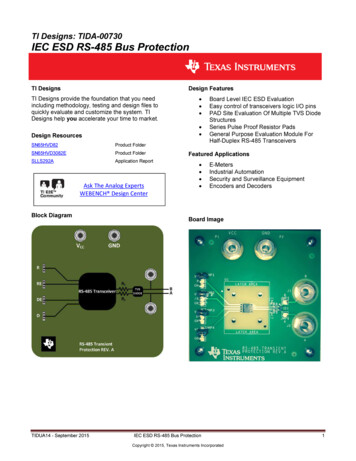
TI Designs: TIDA-00730IEC ESD RS-485 Bus ProtectionDesign FeaturesTI DesignsTI Designs provide the foundation that you needincluding methodology, testing and design files toquickly evaluate and customize the system. TIDesigns help you accelerate your time to market. Design ResourcesSN65HVD82 Product FolderSN65HVD3082EProduct FolderSLLS292AApplication ReportAsk The Analog ExpertsWEBENCH Design CenterBlock DiagramTIDUA14 - September 2015Board Level IEC ESD EvaluationEasy control of transceivers logic I/O pinsPAD Site Evaluation Of Multiple TVS DiodeStructuresSeries Pulse Proof Resistor PadsGeneral Purpose Evaluation Module ForHalf-Duplex RS-485 TransceiversFeatured Applications E-MetersIndustrial AutomationSecurity and Surveillance EquipmentEncoders and DecodersBoard ImageIEC ESD RS-485 Bus ProtectionCopyright 2015, Texas Instruments Incorporated1
www.ti.com1Design OverviewIndustrial networks such as RS-485, RS-422, RS-232, CAN, and Profibus are expected towithstand harsh system-level transients in their end applications without being damaged.These events can be caused by electrostatic discharge during handling, interruption ofinductive loads, relay contact bounce, and/or lightning strikes. Designing to meet theserequirements can be challenging without the proper tools and knowledge about the standardsthat the design requires.TI design TIDA-00730 shows a practical example of how to protect the most sensitivecomponents against these lethal transients. This documentation walks through the TIA/EIA485 standard, the IEC 61000-4-x transient test standards, the implementation of system levelprotection against the transient and overall schematic design/layout.
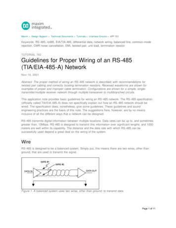
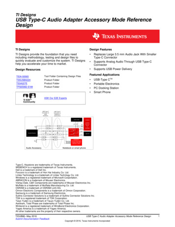
www.ti.com2StandardsThere are many standards that can be referenced by engineers looking to ensure ESDrobustness in their end design. Human Body Model (HBM), Machine Model (MM), andCharged Device Model (CDM) are the most common ESD standards in industry, as mostvendors provide data on these parameters in the supporting documentation for a givendevice. These traditional ESD models do not take into account system-level ESD events andare solely meant as device level specs. These specifications ensure that the device can makeit through the handling and assembly process without being damaged by ESD.HBM, MM, and CDM are sufficient models for many industrial applications but some industrialapplications are subjected too much greater stresses. In the real world the transients that asystem can be subjected to are much more severe than the levels covered by theaforementioned ESD standards. The next three sections will discuss the IEC 61000-4-2Electrostatic Discharge Immunity Test, IEC 61000-4-4 Electrical Fast Transient/BurstImmunity Test, the IEC 61000-4-5 Surge Immunity Test standards and the expected levels ofenergy the industrial system can see.2.1IEC 61000-4-2 Electrostatic Discharge Immunity TestThe IEC 61000-4-2 ESD immunity test is a system-level ESD test that imitates a chargedoperator discharging onto an end system. The characteristics of the IEC ESD test differ fromthat of other ESD standards in rise times, the amount of energy delivered during the strike,and the number of strikes administered during the testing. There are two types of testingmethods involved with the IEC ESD; contact discharge and air discharge. The contact ESDtest discharges an ESD pulse from an IEC ESD gun directly onto the device under test(DUT). The air ESD discharge test involves moving the charged ESD gun towards the DUTuntil the air breaks down enough to allow conduction of the ESD strike between the ESD gunand the DUT. The IEC ESD testing is performed with both positive and negative polarities,and a passing score is not achieved unless both polarities at a single level are survived.Table 1 shows the IEC 61000-4-2 ESD test voltage levels and the peak current levels:Table 1: IEC 61000-4-2 ESD Test Voltage LevelsLevelContact DischargeTest Voltage (kV)1234*2468SpecialPeak Current(A)7.51522.530SpecialAir DischargeLevelTest Voltage (kV)1234*24815Special* is an open level. The level has to be specified in the dedicated equipment speciation. If higher voltages thanthose shown are specified, special test equipment may be needed.Figure 1 depicts the basic shape of the IEC ESD pulse and shows the timing sequence of thetest pulses.TIDUA14 - September 2015IEC ESD RS-485 Bus ProtectionCopyright 2015, Texas Instruments Incorporated3
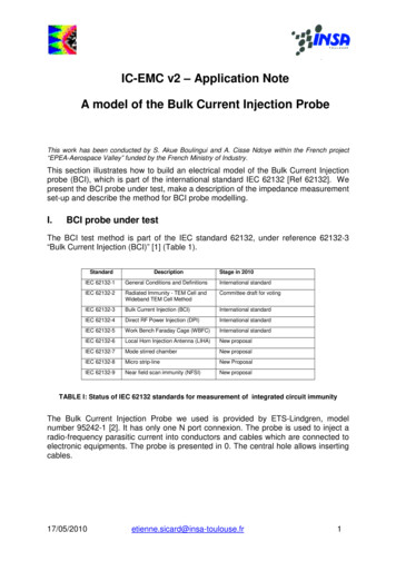
www.ti.comFigure 1: Current Waveform of IEC ESD Pulse and Timing Sequence of Test2.2IEC 61000-4-4 Electrical Fast Transient/Burst Immunity TestThe IEC 61000-4-4 electrical fast transient (EFT) or burst immunity test is meant to simulatethe switching transients caused by the interruption of inductive loads, relay contact bounce,etc. The EFT test is performed on power lines, I/O data lines, I/O control lines and earthwires. The EFT test is a burst of pulses that have predetermined amplitude and limitedduration. The typical duration of a burst is 15 ms at a repetition rate of 5 kHz, although 100kHz repetition is a more realistic test. The burst period, which is the time from the start of oneburst to the start of the next burst, is 300 ms. The test requires the application of six burstframes of ten seconds duration with ten second pauses between frames. In a typical EFT testsequence 3 million pulses will be delivered to the DUT via a capacitive clamp which couplesthe energy into the system. Table 2 below shows the IEC 61000-4-4 EFT test voltage levelsand repetition rates:Table 2: IEC 61000-4-2 ESD Test Voltage LevelsOn I/O Signal, data and control portsTest VoltageRepetition Rate(kV)(kHz)10.255 or 10020.55 or 100315 or 100425 or 100**Special*Is an open level. The level has to be specified in the dedicated equipment specification.LevelOn Power Port, PETest Voltage (kV)Repetition Rate(kHz)0.55 or 10015 or 10025 or 10045 or 100SpecialSpecialFigure 2 below depicts the basic shape of the IEC EFT pulse and shows the timing sequenceof the test pulses.Figure 2: Voltage waveform of an EFT (Burst) Pulse and Timing Sequence of an Entire Test CycleTIDUA14 - September 2015IEC ESD RS-485 Bus ProtectionCopyright 2015, Texas Instruments Incorporated4
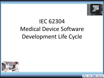
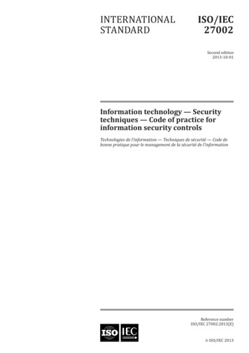
www.ti.com2.3IEC 61000-4-5 Surge Immunity TestThe IEC 61000-4-5 Surge immunity test is the most severe transient immunity test in terms ofcurrent and duration. This test is meant to simulate transients caused by direct or indirectlightning strikes as well as the switching of power systems including load changes and shortcircuits.The surge generator’s output waveforms are specified for open and short circuit conditions.Characteristics for this test are high current (due to low generator impedance) and long pulseduration. Pulse duration for the surge immunity test is approximately 1000 times longer thanthat of IEC ESD and IEC EFT, resulting in high-energy pulses.This test requires five positive surge pulses and five negative surge pulses with a timeinterval between pulses of one minute. Typically though, this time interval is reduced tosomething shorter than one minute to help reduce overall test time.Table 3: IEC Surge Open Circuit Voltage Test LevelsLevel1234*Open-circuit voltage 10% (kV)0.5124Special* Can be any level above, below, or in between the other levels. This level can be specified in the productstandard.Figure 3 below depicts the basic shape of the IEC surge pulse and shows the timingsequence of the test pulses.Figure 3: Voltage and Current waveform of a Surge Pulse and Timing Sequence of a Test Cycle3System DescriptionIn this TI Design, a TVS diode is implemented on each bus line along with series pulse proofresistors to protect the RS-485 transceiver from lethal ESD, EFT (burst), and surgetransients. The TVS diode acts as a clamping circuit to redirect the transient energy to groundwhile the pulse proof resistors act as a current limiter to protect the bus lines from dangerousovervoltage conditions. Figure 4 shows the TI Design with all of its components:TIDUA14 - September 2015IEC ESD RS-485 Bus ProtectionCopyright 2015, Texas Instruments Incorporated5
www.ti.comFigure 4: RS-485 Transceiver with TVS Diode and Series Pulse Proof Resistors44.1TIA/EIA-485 Standard and TransceiversTIA/EIA-485 StandardTIA/EIA-485 is a differential signaling standard which defines the electrical characteristics ofdrivers and receivers used to implement a balanced, multi-point transmission line. Acompliant TIA/EIA-485 transceiver must support a differential signal of 1.5 V across a 54 Ωload as well as a -7 V-to- 12 V common mode voltage range. RS-485 transceivers aredesigned to support a wide range of serial data transmission data rates over very longdistances (up to 1000 meters).Texas Instruments RS-485 transceivers meet or exceed the requirements set by the TIA/EIA485 standard and support other features like automatic polarity correction, receiverequalization, 1.8 V I/O levels, and integrated IEC ESD protection. While all of these featuresare nice to have, this TI Design only focuses on the SN65HVD3082E (a standard 5-V RS-485transceiver), and the SN65HVD82 (a 5-V transceiver with integrated IEC ESD protection).4.1.1 SN65HVD3082EThe SN65HVD308xE family of transceivers support half-duplex operation and are designedfor RS-485 data bus networks. They are powered by a 5-V supply, support data rates up to20 Mbps, and are fully compliant to the TIA/EIA-485 standard.4.1.2 SN65HVD82The SN65HVD82 transceiver supports half-duplex operation and is designed for RS-485 databus networks in demanding industrial applications. The SN65HVD82 is powered by a 5-Vsupply, is optimized for data rates up to 250 kbps, and is fully compliant to the TIA/EIA-485standard. The bus pins, A and B, have integrated ESD protection making them robust to ESDevents with high levels of protection against HBM, Air-Gap Discharge, CDM, IEC 61000-4-2,TIDUA14 - September 2015IEC ESD RS-485 Bus ProtectionCopyright 2015, Texas Instruments Incorporated6
www.ti.comand IEC 61000-4-4. The SN65HVD82 supports 12 kV of IEC ESD protection, 16 kV HBMprotection, and 4kV IEC EFT protection on die.5System Design TheoryThis TI Design features the CDSOT23-SM712 TVS diode from Bourns Inc., series pulse proofresistors, a pad site for an 8 pin SOIC RS-485 transceiver with the SN65HVD82 installed, andbanana jacks for injecting the ESD, EFT, and surge test pulses. The concept behind thedesign is to protect the RS-485 transceiver from lethal transients that can occur in real worldapplications caused by electrostatic discharge during handling, interruption of inductive loads,relay contact bounce, and/or lightning strikes. If the energy that is delivered during one ofthese transient events is large enough in amplitude it can permanently damage the device.The TVS is placed very close the board connector where the bus lines enter the design toensure that any transient energy coupled onto the bus is minimized at the point of origin. TheTVS acts as a clamping circuit to redirect any high energy pulses to ground and away fromthe transceiver. The diode needs to be rated for the type of energy levels that are expectedper the design. This design was done with the IEC 61000-4-2 standard in mind, and theCDSOT23-SM712 is rated for this application.The series pulse-proof resistors on the A and B bus lines limit the residual clamping currentthe transceiver sees if the TVS clamping voltage is higher than the specified maximumvoltage of the transceiver bus pins. These resistors are typically very low in value ( 10-20Ω)and should be selected to accommodate the appropriate power levels.6Getting Started HardwareThe reference design is a simple design that includes pulse proof resistors, a CDSOT23SM712 TVS diode from Bourns, and a SN65HVD82 RS-485 transceiver from TexasInstruments. VCC and GND are connected to the reference design via the banana jacks thatcan be identified via the silkscreen on the board. The device can be placed into drive modeby pulling the driver enable (DE) pin high via the three pin berg header labeled DE. PullingDE low disables the driver. The board can be placed into receive mode by pulling the receiverenable pin low (/RE) via the three pin berg header labeled /RE. Pulling /RE high disables thereceiver. Once the proper mode is enabled, the device functionality can be checked via thethree pin berg header labeled R which is the receiver pin, the three pin berg header labeled Dwhich is the driver pin, and the bus pins via single terminal berg pins labeled A and B.Once device functionality is verified, the transient testing can be done via the two bananajacks connected to the bus pins. The IEC ESD contact test pulses can be injected onto thebus pins by directly touching the banana jacks and discharging the pulses. The IEC ESD airtest pulses can be injected onto the bus pins by using either the banana jacks or the singlepole berg headers by approaching the contact point slowly until the ESD gun discharges.Care should be taken to ensure that the appropriate bus pin is struck during the air testing asthe ESD pulse can jump from pin to pin if the ESD gun is close to both the A and B pins. TheEFT test can be performed by connecting your bus wire to the A and B pins and inserting itinto the capacitive clamp defined by the IEC 61000-4-4 standard. The surge generator usesshielded banana jacks to couple the energy onto the bus pins directly.When performing these types of compliance tests, the test methods should be followed as itis laid out in the standards documentation. After each test level is completed the leakagecurrent should be observed as this is a clear indication that something broke in the device.TIDUA14 - September 2015IEC ESD RS-485 Bus ProtectionCopyright 2015, Texas Instruments Incorporated7
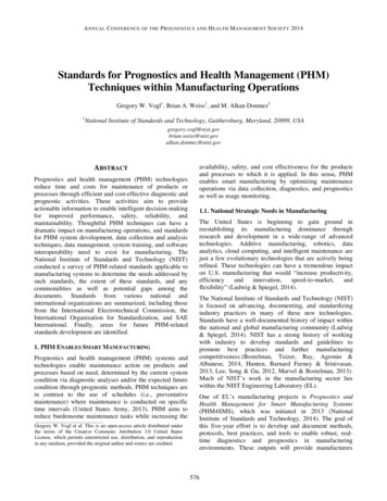
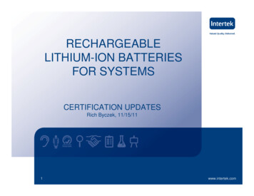
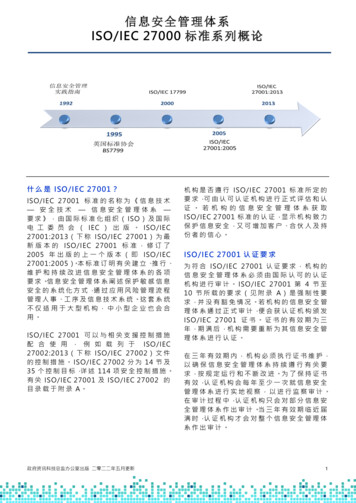
www.ti.comThe device should be checked for general functionality in both the driver and receiverdirections. Figure 5 shows an overview of the board with descriptions of each point.Figure 5: RS-485 Transient EVM Overview7Test SetupFigures 5, 6, and 7 below show the test setups used in the IEC immunity compliance testingfor this RS-485 design. Figure 5 shows the IEC ESD setup. The setup used for this testing isfully compliant to the IEC ESD specification. Figure 6 shows the EFT and surge generatorbox. The EFT/surge generator box is made by EMC-Partner and is model number CDN-UTP.Figure 7 shows the complete test setup with the capacitive clamp defined in the IEC 61000-44 standard as well as the protective cases used to encase the DUTS during testing. Figure 8shows a close up image of the capacitive clamp used to couple the EFT pulses onto the buscable.TIDUA14 - September 2015IEC ESD RS-485 Bus ProtectionCopyright 2015, Texas Instruments Incorporated8
www.ti.comFigure 6: IEC ESD Compliant Test SetupTIDUA14 - September 2015IEC ESD RS-485 Bus ProtectionCopyright 2015, Texas Instruments Incorporated9
www.ti.comFigure 7: Electrical Fast Transient (EFT) and Surge GeneratorTIDUA14 - September 2015IEC ESD RS-485 Bus ProtectionCopyright 2015, Texas Instruments Incorporated10
www.ti.comFigure 8: EFT and Surge Test SetupTIDUA14 - September 2015IEC ESD RS-485 Bus ProtectionCopyright 2015, Texas Instruments Incorporated11
www.ti.comFigure 9: EFT Capacitive Clamp8Test DataBelow the test results for the SN65HVD3082E and the SN65HVD82 are summarized for theIEC 61000-4-2 ESD immunity test, the IEC 61000-4-4 EFT immunity test, and the IEC 610004-5 surge immunity test.Table 4: Summary of Test ResultsProtection SchemeIEC ESD (kV)IEC EFT (kV)IEC Surge (kV)SN65HVD82TVS 30 Contact 4 1 4 1 30 AirSN65HVD3082ETVSTIDUA14 - September 2015 14 Contact 30 AirIEC ESD RS-485 Bus ProtectionCopyright 2015, Texas Instruments Incorporated12
www.ti.comTable 5: IEC ESD Contact Discharge Test ResultsIEC ESD Level 4kV 5kV 6kV 7kV 8kV 9kV 10kV 11kV 12kV 13kV 14kV 15kV 16kV 17kV 18kV 19kV 20kV 21kV 22kV 23kV 24kV 25kV 26kV 27kV 28kV 29kV 30kVIEC ESD 24kV-25kV-26kV-27kV-28kV-29kV-30kVRS-485 IEC ESD Test ResultsPositive Contact ESD StrikesSN65HVD82Board 1Board 2 Board 1Board 2Board 3 TIDUA14 - September 2015Board 3SN65HVD3082Board 1Board 2Board 3 NTNTNTNTNTBoard 1Board 2Board 3 NT NT NT NT NT NT NT NT NT NT NT NT NT NT NTNegative Contact ESD StrikesIEC ESD RS-485 Bus ProtectionCopyright 2015, Texas Instruments Incorporated13
www.ti.comTable 6: IEC ESD Air Discharge Test ResultsRS-485 IEC ESD Test ResultsPositive Air ESD StrikesSN65HVD82SN65HVD3082IEC ESD Level 4kV 5kV 6kV 7kV 8kV 9kV 10kV 11kV 12kV 13kV 14kV 15kV 16kV 17kV 18kV 19kV 20kV 21kV 22kV 23kV 24kV 25kV 26kV 27kV 28kV 29kV 30kVBoard 1Board 2 Board 1Board 2Board 3 IEC ESD -25kV-26kV-27kV-28kV-29kV-30kVTIDUA14 - September 2015Board 3Board 1Board 2Board 3 Board 1Board 2Board 3 Negative Air ESD StrikesIEC ESD RS-485 Bus ProtectionCopyright 2015, Texas Instruments Incorporated14
www.ti.comTable 7: IEC Electrical Fast Transient Test ResultsRS-485 IEC EFT Test ResultsPositive EFT StrikesSN65HVD82 Board 1SN65HVD82 Board 2IEC EFT Level 0.5kV 1kV 2kV 4kVNegative EFT StrikesSN65HVD82 Board 1SN65HVD82 Board 2IEC EFT Level -0.5kV-1kV-2kV-4kVIEC EFT Level SN65HVD82 Board 3 Positive EFT StrikesSN65HVD3082E Board 1 SN65HVD3082E Board 2 SN65HVD3082E Board 3 0.5kV 1kV 2kV 4kVIEC EFT Level SN65HVD82 Board 3 Negative EFT StrikesSN65HVD3082E Board 1 SN65HVD3082E Board 2 SN65HVD3082E Board 3-0.5kV-1kV-2kV-4kVTIDUA14 - September 2015 IEC ESD RS-485 Bus ProtectionCopyright 2015, Texas Instruments Incorporated 15
www.ti.comTable 8: IEC Surge Test ResultsRS-485 IEC Surge Test ResultsPositive Surge StrikesSN65HVD82 Board 1SN65HVD82 Board 2IEC EFT Level 0.5kV 1kV 2kV 4kVNTNTNegative Surge StrikesSN65HVD82 Board 1SN65HVD82 Board 2IEC EFT Level 0.5kV 1kV 2kV 4kVIEC EFT Level SN65HVD82 Board 3 NTNTNegative Surge StrikesSN65HVD3082E Board 1 SN65HVD3082E Board 2 SN65HVD3082E Board 3 0.5kV 1kV 2kV 4kV8.1NTNTNTPositive Surge StrikesSN65HVD3082E Board 1 SN65HVD3082E Board 2 SN65HVD3082E Board 3 1kVIEC EFT Level NT 0.5kV 2kV 4kV SN65HVD82 Board 3NT NTNTNTTest ResultsThe test results show that by adding a TVS diode to the A and B bus lines of both theSN65HVD3082E and SN65HVD82 transceivers, the transient immunity increasessignificantly. The designs pass IEC ESD level 4 criteria, IEC EFT level 4 criteria, and IECsurge level 2 criteria. Both designs also fall into the “special” characteristic per the IEC ESDstandard as the SN65HVD3082E passes IEC ESD up to 14kV while the SN65HVD82passes up to 30kV IEC ESD, surpassing the level 4 ESD voltage.Not every design or application will require 30kV of ESD protection, but for thoseapplications that do, the SN65HVD82 coupled with the CDSOT23-SM712 TVS diode fromBourns will provide this. For designs that do not require this level of protection but need to berated up to level 4 IEC ESD ( 8kV), coupling the SN65HVD3082E with the same CDSOT23SM712 diode takes a standard RS-485 transceiver with no integrated IEC ESD protection to 14kV IEC ESD protection.TIDUA14 - September 2015IEC ESD RS-485 Bus ProtectionCopyright 2015, Texas Instruments Incorporated16
www.ti.com99.19. Design FilesSchematicsTo download the Schematics for each board, see the design files athttp://www.ti.com/tool/tidu00730Figure 10: IEC ESD RS-485 Bus Protection Schematic9.2Bill of MaterialsTo download the Bill of Materials for each board, see the design files athttp://www.ti.com/tool/tidu00730TIDUA14 - September 2015IEC ESD RS-485 Bus ProtectionCopyright 2015, Texas Instruments Incorporated17
www.ti.comTable 1: TIDA-00730 BOMBill Of MaterialsTIDA-00730 – IEC ESD RS-485 Bus uF1uF0.1uF10uf1uFDNITVSHeader 3x1Header 1x1102J1,J2, P1, P2Solderless Banana Jack111213621R3,R4,R5,R6,R7,R8R10,R11U149.9108D tecSamtecEmerson Network PowerCoAnyAnyTexas InstrumentsManufacturer Part NumberAny (5V Rating)Any (5V Rating)Any (5V Rating)Any (5V Rating)Any (5V Rating)Any (5V PCB Footprint120608050603734304020603SOT 23 321berg1x3berg1x1108-0740-001Any (1% Tolerance)Any (1% Tolerance)SN65HVD82060306038Pin D
www.ti.comPCB Layout Recommendations1) Place the protection circuitry close to the bus connector to prevent noise transientsfrom entering the board.2) Use VCC and ground planes to provide low-inductance.i. NOTE: High-frequency currents follow the path of least inductance andnot the path of least impedance.3) Design the protection components into the direction of the signal path. Do not forcethe transient’s currents to divert from the signal path to reach the protection device.4) Apply 100-nF to 220-nF bypass capacitors as close as possible to the VCC pins oftransceiver, UART, and controller ICs on the board.5) Use at least two vias for VCC and ground connections of bypass capacitors andprotection devices to minimize effective via-inductance.6) Use 1-kΩ to 10-kΩ pull up or pulldown resistors for enable lines to limit noise currentsin these lines during transient events.7) Insert series pulse-proof resistors into the A and B bus lines if the TVS clampingvoltage is higher than the specified maximum voltage of the transceiver bus pins.These resistors limit the residual clamping current into the transceiver and prevent itfrom latching up.54CRVia to groundVia to VCC6 R1RMCUR75R6 RSN65HVD82/3082EFigure 11: Layout ExampleJMP9.35TVS
www.ti.com9.3.1 Layout PrintsTo download the Layout Prints for each board, see the design files athttp://www.ti.com/tool/tidu00730TOP SILKSCREENFigure 12: Top SilkscreenTOP SOLDER MASKFigure 13: Top Solder MaskTIDUA14 - September 2015IEC ESD RS-485 Bus ProtectionCopyright 2015, Texas Instruments Incorporated20
www.ti.comTOP LAYERFigure 14: Top LayerBOTTOM LAYERFigure 15: Bottom LayerTIDUA14 - September 2015IEC ESD RS-485 Bus ProtectionCopyright 2015, Texas Instruments Incorporated21
www.ti.comBOTTOM SOLDER MASKFigure 16: Bottom Solder MaskBOTTOM SILKSCREENFigure 17: Bottom SilkscreenTIDUA14 - September 2015IEC ESD RS-485 Bus ProtectionCopyright 2015, Texas Instruments Incorporated22
www.ti.comMECHANICAL DIMENSIONSFigure 18: Mechanical DimensionsTIDUA14 - September 2015IEC ESD RS-485 Bus ProtectionCopyright 2015, Texas Instruments Incorporated23
www.ti.com9.4Layout GuidelinesFigure 19: Layout GuidelinesTIDUA14 - September 2015IEC ESD RS-485 Bus ProtectionCopyright 2015, Texas Instruments Incorporated24
www.ti.com9.5Gerber filesTo download the Gerber files for each board, see the design files at http://www.ti.com/tool/tidu00730Figure 20: Gerber File
www.ti.com9.6Assembly DrawingsTo download the Assembly Drawings for each board, see the design files athttp://www.ti.com/tool/tidu00730Figure 21: Assembly DrawingTIDUA14 - September 2015IEC ESD RS-485 Bus ProtectionCopyright 2015, Texas Instruments Incorporated26
www.ti.com10 References1. Texas Instruments Application Report, Protecting RS-485 Interfaces Against Lethal ElectricalTransients, SLLA292A, 200911 About the AuthorMichael Peffers is an applications engineer at Texas Instruments supporting the RS-485, LVDS,PECL, CAN, LIN, IO-Link, and Profibus interface products. Michael is responsible for developingreference designs solutions for the industrial segment and direct customer support including onsitesupport as well as onsite training. Michael is also responsible for producing technical content such asapplication notes, datasheets, white papers, and is the author of a recurring blog on the TexasInstruments E2E forum called Analog Wire: Get Connected. Michael brings to this role his experiencein high-speed SERDES applications as well as experience in the optical transceiver space. Michaelearned his Bachelors of Science in Electrical Engineering (BSEE) from the University of Central Florida(UCF).TIDUA14 - September 2015IEC ESD RS-485 Bus ProtectionCopyright 2015, Texas Instruments Incorporated27
IMPORTANT NOTICE FOR TI REFERENCE DESIGNSTexas Instruments Incorporated ("TI") reference designs are solely intended to assist designers (“Buyers”) who are developing systems thatincorporate TI semiconductor products (also referred to herein as “components”). Buyer understands and agrees that Buyer remainsresponsible for using its independent analysis, evaluation and judgment in designing Buyer’s systems and products.TI reference designs have been created using standard laboratory conditions and engineering practices. TI has not conducted anytesting other than that specifically described in the published documentation for a particular reference design. TI may makecorrections, enhancements, improvements and other changes to its reference designs.Buyers are authorized to use TI reference designs with the TI component(s) identified in each particular reference design and to modify thereference design in the development of their end products. HOWEVER, NO OTHER LICENSE, EXPRESS OR IMPLIED, BY ESTOPPELOR OTHERWISE TO ANY OTHER TI INTELLECTUAL PROPERTY RIGHT, AND NO LICENSE TO ANY THIRD PARTY TECHNOLOGYOR INTELLECTUAL PROPERTY RIGHT, IS GRANTED HEREIN, including but not limited to any patent right, copyright, mask work right,or other intellectual property right relating to any combination, machine, or process in which TI components or services are used.Information published by TI regarding third-party products or services does not constitute a license to use such products or services, or awarranty or endorsement thereof. Use of such information may require a license from a third party under the patents or other intellectualproperty of the third party, or a license from TI under the patents or other intellectual property of TI.TI REFERENCE DESIGNS ARE PROVIDED "AS IS". TI MAKES NO WARRANTIES OR REPRESENTATIONS WITH REGARD TO THEREFERENCE DESIGNS OR USE OF THE REFERENCE DESIGNS, EXPRESS, IMPLIED OR STATUTORY, INCLUDING ACCURACY ORCOMPLETENESS. TI DISCLAIMS ANY WARRANTY OF TITLE AND ANY IMPLIED WARRANTIES OF MERCHANTABILITY, FITNESSFOR A PARTICULAR PURPOSE, QUIET ENJOYMENT, QUIET POSSESSION, AND NON-INFRINGEMENT OF ANY THIRD PARTYINTELLECTUAL PROPERTY RIGHTS WITH REGARD TO TI REFERENCE DESIGNS OR USE THEREOF. TI SHALL NOT BE LIABLEFOR AND SHALL NOT DEFEND OR INDEMNIFY BUYERS AGAINST ANY THIRD PARTY INFRINGEMENT CLAIM THAT RELATES TOOR IS BASED ON A COMBINATION OF COMPONENTS PROVIDED IN A TI REFERENCE DESIGN. IN NO EVENT SHALL TI BELIABLE FOR ANY ACTUAL, SPECIAL, INCIDENTAL, CONSEQUENTIAL OR INDIRECT DAMAGES, HOWEVER CAUSED, ON ANYTHEORY OF LIABILITY AND WHETHER OR NOT TI HAS BEEN ADVISED OF THE POSSIBILITY OF SUCH DAMAGES, ARISING INANY WAY OUT OF TI REFERENCE DESIGNS OR BUYER’S USE OF TI REFERENCE DESIGNS.TI reserves the right to make corrections, enhancements, improvements and other changes to its semiconductor products and services perJESD46, latest issue, and to discontinue any product or service per JESD48, latest issue. Buyers should obtain the latest relevantinformation before placing orders and should verify that such information is current and complete. All semiconductor products are soldsubject to TI’s terms and conditions of sale supplied at the time of order acknowledgment.TI warrants performance of its components to the specifications applicable at the time of sale, in accordance with the warranty in TI’s termsand conditions of sale of semiconductor products. Testing and other quality control techniques for TI components are used to the extent TIdeems necessary to support this warranty. Except where mandated by applicable law, testing of all parameters of each component is notnecessarily performed.TI assumes no liability for applications assistance or the design of Buyers’ products. Buyers are responsible for their products andapplications using TI components. To minimize the risks associated with Buyers’ products and applications, Buyers should provideadequate design and operating safeguards.Reproduction of significant portions of TI information in TI data books, data sheets or reference designs is permissible only if reproduction iswithout alteration and is accompanied by all associated warranties, conditions, limitations, and notices. TI is not responsible or liable forsuch altered documentation. Information of third parties may be subject to additional restrictions.Buyer acknowledges and agrees that it is solely responsible for compliance with all legal, regulatory and safety-related requirementsconcerning its products, and any use of TI components in its applications, notwithstanding any applications-related information or supportthat may be provided by TI. Buyer represents and agrees that it has all the necessary expertise to create and implement safeguards thatanticipate dangerous failures, monitor failures and their consequences, lessen the likelihood of dangerous failures and take appropriateremedial actions. Buyer will fully indemnify TI and its representatives against any damages arising out of the use of any TI components inBuyer’s safe
20 Mbps, and are fully compliant to the TIA/EIA-485 standard. 4.1.2 SN65HVD82 The SN65HVD82 transceiver supports half-duplex operation and is designed for RS-485 data bus networks in demanding industrial applications. The SN65HVD82 is powered by a 5-V supply, is optimized for data rates up to 250 kbps, and is fully compliant to the TIA/EIA-485