Transcription
TI DesignsUSB Type-C Audio Adapter Accessory Mode ReferenceDesignTI DesignsDesign FeaturesTI Designs provide the foundation that you needincluding methodology, testing and design files toquickly evaluate and customize the system. TI Designshelp you accelerate your time to market. Design Resources TIDA-00565Tool Folder Containing Design FilesTS5USBA224TS3A227ETPS65982-EVMProduct FolderProduct FolderProduct Folder Replaces Large 3.5 mm Audio Jack With SmallerType-C ConnectorSupports Analog Audio Through USB Type-CConnectorSupports USB Power DeliveryFeatured Applications USB-Type CTMPortable ElectronicsPC Docking StationSmart PhoneASK Our E2E ExpertsUSB Type-CConnector onaudioaccessoryUSB Type-CConnector onnotebook orsmart phoneAudio CodecTUSB32XL/R L/RCC1RaRaRaCC1SBU1SBU1TS5USBA224GPIOD D-D-D D /-D-D D D-D /-Headset/SpeakerSBU2SBU2CC2CC2RaAudio AccessoryCC1/CC2detectiondeviceorTPS65982USB PHYTS3A227EMic/GND Autonomous audioheadset Mic/GNDMic/GNDdetection switchNotebook or smart phoneType-C, Keystone are trademarks of Texas Instruments.WEBENCH is a registered trademark of Texas Instruments.Dell is a trademark of Dell Inc.Foxconn is a trademark of Hon Hai Industry Co. Ltd.Lintes Technology is a trademark of Lintes Technlogy Co. Ltd.Windows is a registered trademark of Microsoft Corportation.ABRACON is a trademark of Mouser Electronics.Vishay-Dale, C&K Components are trademarks of Mouser Electronics Inc.MuRata is a trademark of MuRata Manufacturing Co. Ltd.OSRAM is a trademark of OSRAM Licht AG.Omron Electronic Components is a trademark of Omron Corporation.Samsung is a trademark of Samsung Electronics.Sullins Connector Solutions is a trademark of Sullins Connector Solutions Inc.TDK is a registered trademark of TDK Corporation.Taiyo Yuden is a trademark of Tauyo Yuden Co. Ltd.Aardvark, Total Phase are trademarks of Total Phase Inc.Winbond is a registered trademark of Windbond Electronics Corporation.Yageo America is a trademark of Yageo America.All other trademarks are the property of their respective owners.TIDUB66 – May 2016Submit Documentation FeedbackUSB Type-C Audio Adapter Accessory Mode Reference DesignCopyright 2016, Texas Instruments Incorporated1
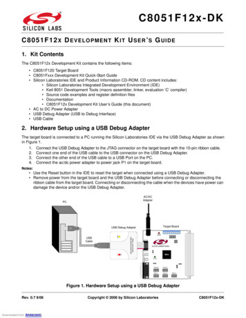
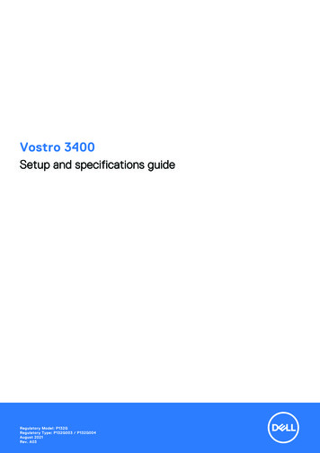
Quick Start Guidewww.ti.comAn IMPORTANT NOTICE at the end of this TI reference design addresses authorized use, intellectual property matters and otherimportant disclaimers and information.1Quick Start Guide1.1Getting Started HardwareRequired hardware for a demonstration of the audio adapter accessory mode: TIDA-00565 demo board. 19 V barrel jack power supply for the TIDA-00565 board. An audio source such as a PC or a smart phone. Cable with a 3.5 mm male jack to a 3.5 mm male jack to interface the audio source to the 3.5mm jackon the TIDA00565 board Pair of headphones or speaker USB Type-C audio adapter with a 3.5 mm female jack to a USB Type-C male connector. (not needed ifan audio headset or speaker with a USB Type-C connector is available)1.2Getting Started Procedure1. Plug in a 19 V power supply into the barrel jack of the TIDA-00565 board which provides power.2. Plug in an audio source into the 3.5 mm jack of the TIDA-00565 board.3. Plug in a pair of headphones and a speaker with a USB Type-C connector, or use the audio adapterboard to interface the headphones and speaker with a 3.5 mm jack to USB Type-C Connector.Figure 1 shows the TIDA-00565 with 19 V barrell jack power supply, 3.5mm male to male cable,headphones, and 3.5 mm jack to the USB Type-C adaptor board.Figure 1. TIDA-00565 and 3.5 mm Jack to The USB Type-C Adaptor Board2USB Type-C Audio Adapter Accessory Mode Reference DesignCopyright 2016, Texas Instruments IncorporatedTIDUB66 – May 2016Submit Documentation Feedback
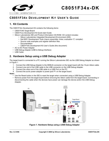
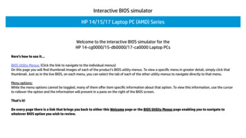
Quick Start Guidewww.ti.comFigure 2 shows the location of the key components on the TIDA-00565 board.Barrel JackPlug in power supply intothis socket3.5mm JackPlug in the audiosource into thisconnectorTPS65982Full featured powerdelivery IC. Onlyleveraging CC1 andCC2 detection featurefor this designTS5USBA224Used to switch theD /D- trace from USBType C connector tothe L/R or D /DtracesUSB Type-CConnectorPlug in USB type Caudio accessoryadapter into thisconnectorFigure 2. Location of Key Components on the TIDA-00565 Board1.3Purpose of TS5USBA224The TS5USBA224 is used to multiplex between the USB 2.0 data and analog audio in order to protect theUSB PHY from the negative voltage swings of the analog audio. The analog audio and USB data travelover the D and D- lines in the USB Type-C connector. When an analog audio signal is on the USB D and D- lines, the signal may swing up to –2 to 2 Vpp. This negative swing in voltage can cause damage tocomponents in the signal chain that may not be able to handle a negative swinging signal.The TS3A227E is used specifically to automatically detect and orient the MIC and GND signals of the 3.5mm jack to support the function described in the USB Type-C standard above. Refer to the TS3A227EAutonomous Audio Accessory Detection and Configuration Switch datasheet (SCDS358B) for more detailson the automated detection. The USB Type-C to 3.5 mm dongle is on the sink side of the system,therefore, the system user may connect speakers or a headphone set to listen to the audio. Headphonesoften come with a 4-pole jack, which means the MIC and GND of the jack must be routed properly.1.4Purpose of the TS3A227EThe USB Type-C standard states, “The system shall connect A6/B6, A7/B7, A8 and B8 to an appropriateaudio codec upon entry into the audio adapter accessory mode. The connections for A8 (SBU1) and B8(SBU2) pins are dependent on the adapter’s orientation. Depending on the orientation, the microphoneand analog ground pins may be swapped. These pins are already reversed between the two majorstandards for headset jacks and support for this is built into the headset connection of many codecs, ormay be implemented using an autonomous audio headset switch. The system works correctly with eitherconfiguration."1.5Purpose of the TUSB321X / TPS65982The TUSB32X or TPS65982 device enables USB Type-C ports with the configuration channel (CC) logicneeded for USB Type-C ecosystems. The TUSB32X/TPS65982 device use the CC pins to determine thetype of device inserted into the USB Type-C connector. When the TUSB32X/TPS65982 device sees anaudio accessory (by sensing the Ra 1k pull down resistors on the accessory) it can use one of its GPIOsto toggle the TS5USBA224 logic control pins to select the audio path of the TS5USBA224.TIDUB66 – May 2016Submit Documentation FeedbackUSB Type-C Audio Adapter Accessory Mode Reference DesignCopyright 2016, Texas Instruments Incorporated3
Design Overview2www.ti.comDesign OverviewThe USB Type-CTM audio adapter accessory mode reference design provides the solution for interfacinganalog audio through the emerging USB Type-C interface. This reference design demonstrates howanalog audio may be transmitted to system peripherals using the USB Type-C standard’s audio adapteraccessory mode. This allows designs to remove the large 3.5 mm jack, and replace it with an 85% smallerUSB Type-C receptacle.3Key System SpecificationsTable 1 shows the USB Type-C Analog Audio Pin Electrical Parameter Ratings.Table 1. USB Type-C Analog Audio Pin Electrical Parameter Ratings4PLUGPINUSB .0VA6 and B6 must be shorted togetherin the analog audio adapter.A7/B7DnLeft–3.03.0VA7 and B7 must be shorted togetherin the analog audio .43.3VUNITSNOTESSystem DescriptionThe USB Type-C audio adapter accessory mode reference design is composed of two boards; a USBType-C analog audio multiplexer board and a USB Type-C connector to a 3.5 mm jack adapter. The USBType-C analog audio multiplexer board controls the switching between analog audio transferred throughthe USB Type-C connector and data transferred through the USB Type-C connector. The USB Type-C to3.5 mm jack adapter board provides the required pull down resistors for the USB Type-C presence detectlogic on CC1 and CC2 that signifies an audio adapter is being used. The adapter also allows users to testaudio with existing audio devices that use the 3.5 mm jack interface.4USB Type-C Audio Adapter Accessory Mode Reference DesignCopyright 2016, Texas Instruments IncorporatedTIDUB66 – May 2016Submit Documentation Feedback
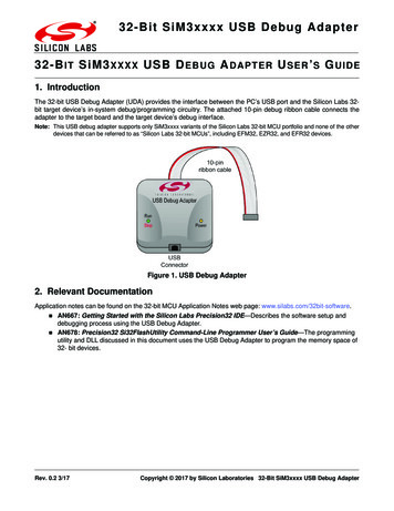
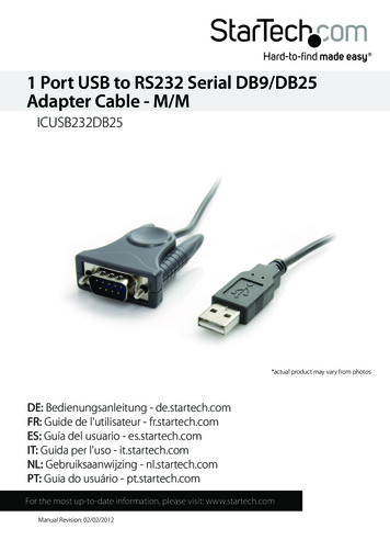
Block Diagramwww.ti.com5Block DiagramThe USB-C Analog Audio TI Design allows for analog audio to be passed over USB Type-C connectionwhile protecting the USB PHY from negative voltages swings from the analog audio. In Figure 3, the audiosource may be produced through a computer, while the audio sink may be a speaker to listen to the audio.Figure 3 shows the TIDA00565 functional block diagram.USB Type-CConnector onaudioaccessoryUSB Type-CConnector onnotebook orsmart phoneAudio CodecTUSB32XL/R L/RRaCC1CC1SBU1SBU1TS5USBA224RaRaGPIOD D-D-D D /-D-D D D-D /-Headset/SpeakerRaAudio 65982USB PHYTS3A227EMic/GND Autonomous audioheadset Mic/GNDMic/GNDdetection switchNotebook or smart phoneFigure 3. TIDA00565 Functional Block DiagramTIDUB66 – May 2016Submit Documentation FeedbackUSB Type-C Audio Adapter Accessory Mode Reference DesignCopyright 2016, Texas Instruments Incorporated5
System Design Theory6www.ti.comSystem Design TheoryThis TIDA00565 system is designed to prove in a simple demonstration how analog audio may be passedover USB Type-C connector. Left and right analog audio is passed through the USB-C connector throughthe D and D- lines of the USB Type-C connector. Simply passing audio through USB-C is possiblewithout the use of ICs, but it is not practical as the negative signal swing of the audio signal can damageother components in the system. The TS5USBA224 provides the ability to pass analog audio withoutallowing the negative signal swing of the audio damage any other parts of the system6.1USB Type-C Audio Adapter Accessory ModeAnalog audio headsets are supported by multiplexing four analog audio signals onto pins on the USBType-C connector when in the audio adapter accessory mode. The audio adapter accessory mode isdeclared to the host by placing two (Ra) pull down resistors on the CC1 and CC2 pins. These resistors onthe CC lines are dictated by the USB Type-C specification.The four analog audio signals are the same as those used by a traditional 3.5 mm headset jack. Thisadapter makes it possible to interface existing analog headsets with a 3.5 mm to USB Type-C adapter forthis demonstration. The adapter also provides the two 1k ohm (Ra) pull down resistors.Figure 4 shows theexample schematics of a passive 3.5 mm jack to the Type-C connector adapter.Figure 4. Example Schematic of a Passive 3.5 mm Jack to the USB Type-C Connector Adapter6USB Type-C Audio Adapter Accessory Mode Reference DesignCopyright 2016, Texas Instruments IncorporatedTIDUB66 – May 2016Submit Documentation Feedback
System Design Theorywww.ti.comTable 2 shows the analog audio pins to the USB-C pins.Table 2. Analog Audio Pins to the USB Type-C PinsPIN NAMEUSB NAMEANALOGAUDIOFUNCTIONLOCATION ON 3.5 MM JACKNOTESA6B6D Right channelRing1Analog audio right channelA6 and B6 are shortedtogetherA7B7D–Left channelTipAnalog audio left channelA7 and B7 are shortedtogetherAudio ground ormicrophone.Need an autonomousdetection switch in thesystem such as theTS3A227E to route thesignals appropriately.A8B8SBU1SBU2A5B5CCConnected to groundthrough 1 k resistors foradapter presence logic.A2/A3 A10/AllB2/B3 B10/B11TX /TX–RX /RX–Not used in audio accessorymode.A4/ A9B4/B9VBUSNot used unless audioadapter uses this for 5 V500 mA charging.TIDUB66 – May 2016Submit Documentation FeedbackMic or AGNDRing 2 or SleeveUSB Type-C Audio Adapter Accessory Mode Reference DesignCopyright 2016, Texas Instruments Incorporated7
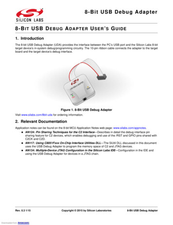
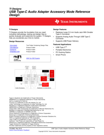
Total Harmonic Distortion Measurement (THD N)7www.ti.comTotal Harmonic Distortion Measurement (THD N)The Total Harmonic Distortion (THD) for the TIDA-00565 was measured using SYS-2722 (192k) AudioPrecision equipment. A 1-V pp sine wave was sent through the D and D- lines of the USB Type-Cconnector, while the TS5USBA224 device audio path was selected. A 600-Ω load was provided by theaudio precision equipment as shown in Figure 34, the THD N test set up screen shot in .Figure 5 shows the test data.Figure 5. Test Data8USB Type-C Audio Adapter Accessory Mode Reference DesignCopyright 2016, Texas Instruments IncorporatedTIDUB66 – May 2016Submit Documentation Feedback
Design Fileswww.ti.com8Design Files8.1SchematicsTo download the schematics for each board, see the design files at http://www.ti.com/tool/TIDA-00565.Figure 6 shows the TIDA-00565 power delivery schematic, Figure 7 shows the TIDA-00565 power pathschematic, and Figure 8 shows the TIDA-00565 USB Type-C audio dongle schematic.Back to Back N FET Configuration30V Rated NFET RecommendedQ1Q2R10.01J6LDO 0D7H6GPIO0GPIO1GPIO2GPIO3GPIO4 HPDGPIO5 HPDGPIO6GPIO7GPIO8I2C SCL1I2C SDA1I2C IRQ1ZI2C SCL2I2C SDA2I2C IRQ2ZSPI MOSISPI MISOSPI CSZSPI CLKGPIO0GPIO1GPIO2GPIO3GPIO4 HPDGPIO5 HPDGPIO6GPIO7GPIO8DEBUG CTL1DEBUG CTL2UART RXUART TXHV GATE2A9RESETD6RESETF11MRESETE11A10C USB TPC USB TNC USB BPC USB BNAUX PAUX NU2BC SBU1C D8E5E6E7E8F5F6F7F8G5G6G7G8H4H5H8L1MRESETK6L6C USB T B NC USB T B PK7L7C USB T B NC USB T B PK8L8C SBU PC SBU NDGNDGNDGNDGNDGNDH11J10J11K11PP HVPP HVPP HVPP HVA8A7A6B7C410µFC50.1µFPP 5V0PP 5V0PP 5V0PP 5V0A11B11C11D11C1122µFC120.1µFPP CABLEVIN 3V3H1LDO 3V3LDO 1V8DC70.01µFC80.01µFC90.01µFHV SourceC100.01µFGNDH5H6TP4System 5VH2GND20-0000016-01C131µFC1410µFC171µFTiva 3V3VOUT 3V3UART TXUART RXAUX PAUX NSPI CLKI2C IRQ1ZI2C SCL1I2C SDA1VOUT 40R69R712468101214161820GND135791113151719Tiva 5VDNPDNPDNPDNPDNPDNP00R16R17R32R36R35R37R39R41NCDD ASELLR11032GNDGNDSWD CLKLDO 1V8D100kVAUDIOGND4GNDVDDC USB T B NC USB T B PC AUDIO T B NC AUDIO T B PRING2 SENSEMIC PRESENTSLEEVE SENSE93I2C SCL1I2C SDA1/INTTIPDET TRIGGERR1054.70k/MIC PRESENT GNDGNDPADGND SENSE14C AUDIO T B NR70 GPIO4 HPD15GPIO6100k7GND812C SBU P10C SBU NS1111234GPIO1DEBUG 3DEBUG 4GPIO5 33100k100k100k100k1.00k1.00k1.00k1.00kLSX R2PGPIO5 HPDGPIO3GPIO2GPIO8DEBUG 1DEBUG 4DEBUG 3USB2 RP R792468101214161820135791113151719I2C SCL2I2C SDA2I2C IRQ2ZI2C IRQ1ZI2C SCL1I2C SDA1GND3.83kR803.83kDEBUG 1C SBU PC SBU NC CC1C CC2Q10112D1 D1-67910NCNCNCNCGNDD2 D2-GNDGND25341C AUDIO T B NC AUDIO T B PJ8GNDGNDUSB2.0 Top/BottomESD ProtectionU345C SBU NC SBU P83GNDTPD4E05U06DQAC USB AUDIO T B NC USB AUDIO T B PC USB AUDIO T B PC USB AUDIO T B N12D1 D1-D2 912GPIO333R96560LSX P2RMRESETRESETZGPIO6SPI MOSISPI MISODEBUG 2SPI CSZUSB2 RP NSJ-43515TS-SMT-TRI2C Pull-Ups for I2C1 & I2C21222Q81C CC2C CC1R48R51R54R58R60R62R64R66R68LDO 3V33.83kR779.09kCC1/CC2 & SBU1/SBU2ESD G 21111D3White2D2WhiteDNPDNPDNPDNP00DNP0DNPLDO 3V3PD & Alternate ModeConfiguration SwitchGNDJ30DNPDNPDNPDNPDNPDNPDNPDNPDNPSystem 5V2LDO 3V3R24GNDU8System 3V3VBUSC54 TS5USBA224RSWR1µFQ3GNDR203.83kL11R984.70kD-/LD /R1I2C IRQ2ZI2C SDA2I2C SCL2GPIO7GPIO0GPIO1SWD DATAGNDH7R10610.0kGPIO7VBUSC SBU NC USB AUDIO T B NC USB AUDIO T B PC CC2VBUSH1H2H1H2GNDLDO 3V3GNDB12B11B10B9B8B7B6B5B4B3B2B1GNDRX1 RX1VBUSSBU2DD CC2VBUSTX2TX2 GNDJ2System 3V3G1K1H5H6H4H3H4H3GNDTX1 TX1VBUSCC1D DSBU1VBUSRX2RX2 GNDGNDGNDB1LDO 1V8A21 ohmH10VDDIOVOUT 3V3VBUSC CC1VBUS C USB AUDIO T B PC USB AUDIO T B NC SBU PVBUSL1VBUSVBUSVBUSVBUSTPS65982AAZQZRSS5LDO BMCF10GNDRESETZH7H8A1A2A3A4A5A6A7A8A9A10A11A12C3 0.22µFDEBUG3DEBUG49E1TP3System RESETC211µFDEBUG1DEBUG28C430.1µFDNPHV GATE2USB RP PUSB RP N67GPIO6R30C18RPD G2U9GNDDNPHV GATE1TPS65982AAZQZRSystem 3V3R22System 3V3L3K3C USB AUDIO T B NC USB AUDIO T B PGNDSENSENB9LDO 3V3GNDGNDRPD G1SPI MISOJ1GNDSENSEP3.3kGNDH7H8GNDLSX R2PLSX P2RL2K2DEBUG 3DEBUG 4SENSENB10R8TP1C19220pFSWD DATASWD CLKL5K5DEBUG 1DEBUG 2SENSEP3.3k4C CC20SPI MOSIR9W25Q80DVSNIGD1SPI MOSISPI MISOSPI SSZSPI CLKUART RXUART TXC61µFGNDB4A4B3A3DEBUG CTL1DEBUG CTL2CLKTP2R11HV GATE1J1J2USB2 RP NUSB2 RP P0RPD G2K10I2C SCL2I2C SDA2I2C IRQ2ZF2E2HV GATE2GNDR10B5A5B6E4D5C CC1HV GATE1RPD G1L10I2C SCL1I2C SDA1I2C IRQ1ZK4L4LSX R2PLSX P2RAUX PAUX NC CC2RPD G2C15220pFL9K9D2D1C1F4G4SWD DATASWD CLKC CC1RPD I2C ADDRCS3F16VCC201SPI CLKGNDR73.3kU18SPI CSZ1R56R OSCGNDR601R28 15.0k G2R501,2,37,8 7,85,6, 5,6,R303U2AR202External PowerGNDFigure 6. TIDA-00565 Power Delivery SchematicsTIDUB66 – May 2016Submit Documentation FeedbackUSB Type-C Audio Adapter Accessory Mode Reference DesignCopyright 2016, Texas Instruments Incorporated9
Design Fileswww.ti.comU5C201External PowerC2210µFC230.1µFR81DNPVINBOOTL29J90.1µF3V3 stem PJ4External Power3V3 DGNDJ5321System 3V3System 5VHV SourceU6C31External .1µF5V VSENSEGND8R93DNP10COMPENGNDGNDGNDPADRTSystem D345115V R27C39100pFGNDC41DNPSystem RESETC402200pF1.00kGNDSystem 3V3GNDGNDJ7System 5VSystem 3V31324Tiva 5VTiva 3V3U7C421External PowerC4410µFC450.1µFR101DNPGNDBOOTL490.1µF12V V 0kC49DNP12V 10947.5kC52DNPC511800pFGNDGNDGNDFigure 7. TIDA-00565 Power Path Schematic10USB Type-C Audio Adapter Accessory Mode Reference DesignCopyright 2016, Texas Instruments IncorporatedTIDUB66 – May 2016Submit Documentation Feedback
Design Fileswww.ti.comFigure 8. TIDA-00565 USB Type-C Audio Dongle SchematicTIDUB66 – May 2016Submit Documentation FeedbackUSB Type-C Audio Adapter Accessory Mode Reference DesignCopyright 2016, Texas Instruments Incorporated11
Design Files8.2www.ti.comBill of Materials (BOM)To download the bill of materials (BOM), see the design files at TIDA-00565.Table 3. Bill of Materials12DESIGNATORDESCRIPTIONMANUFACTURERPART NUMBERQUANTITY!PCB1Printed Circuit BoardAnyTIDA-005651C1, C4CAP, CERM, 10 µF, 25 V, 20%, X5R, 0603MuRata GRM188R61E106MA732C2, C12CAP, CERM, 0.1 µF, 10 V, 10%, X5R, 0201Samsung CL03A104KP3NNNC2C3CAP, CERM, 0.22 µF, 6.3 V, 20%, X5R, 0201MuRataGRM033R60J224ME901C5, C20,C23, C26,C31,C34, C37,C42, C45,C48CAP, CERM, 0.1 µF, 50 V, 20%, C0G/NP0, 0402,CAP, CERM, 0.1 uF, 50 V, 20%, C0G/NP0, 0402,CAP, CERM, 0.1 uF, 50V, 20%, C0G/NP0, 0402,CAP, CERM, 0.1 uF, 50V, 20%, C0G/NP0, 0402,CAP, CERM, 0.1uF, 50 V, 20%, C0G/NP0, 0402,CAP, CERM, 0.1uF, 50V, 20%, C0G/NP0, 0402,CAP, CERM, 0.1 uF, 50V, 20%, C0G/NP0, 0402,CAP, CERM, 0.1uF, 50V, 20%, C0G/NP0, 0402,CAP, CERM, 0.1 uF, 50V, 20%, C0G/NP0, 0402,CAP, CERM, 0.1 uF, 50 V, 20%, C0G/NP0, 0402TDK C1005X7R1H104M10C6CAP, CERM, 1 µF, 35 V, 10%, JB, 0402TDKC1005JB1V105K050BC1C7–C10CAP, CERM, 0.01 µF, 50 V, 10%, X7R, 0402MuRataGRM155R71H103KA88D4C11CAP, CERM, 22 µF, 10 V, 20%, X5R, 0603MuRataGRM188R61A226ME15D1C13,C16–C18CAP, CERM, 1 µF, 10 V, 20%, X5R, 0201SamsungCL03A105MP3NSNC4C14CAP, CERM, 10 µF, 10 V, 20%, X5R, 0402SamsungCL05A106MP5NUNC1C15, C19CAP, CERM, 220 pF, 25 V, 10%, X7R, 0201MuRataGRM033R71E221KA01D2C21, C54CAP, CERM, 1 µF, 6.3 V, 20%, X5R, 0402MuRataGRM152R60J105ME15D2C22, C33,C44CAP, CERM, 10 µF, 25 V, 10%, X5R, 0805TDKC2012X5R1E106K125AB3C24, C25,C35,C36, C46,C47CAP, CERM, 22 µF, 35 V, 20%, X5R, 0805TDKC2012X5R1V226M125AC6C27, C30,C38,C41, C49,C52CAP, CERM, 120 pF, 50 V, 5%, C0G/NP0, 0402MuRataGRM1555C1H121JA01D6C28CAP, CERM, 330 pF, 50 V, 5%, C0G/NP0, 0402TDKC1005C0G1H331J1C29CAP, CERM, 5600 pF, 50 V, 10%, X7R, 0402MuRata'GRM155R71H562KA88D1USB Type-C Audio Adapter Accessory Mode Reference DesignCopyright 2016, Texas Instruments IncorporatedTIDUB66 – May 2016Submit Documentation Feedback
Design Fileswww.ti.comTable 3. Bill of Materials (continued)DESIGNATORDESCRIPTIONMANUFACTURERPART NUMBERQUANTITYC32, C43CAP, CERM, 0.1 µF, 6.3 V, 10%, X7R, 0402MuRataGRM155R70J104KA01D2C39CAP, CERM, 100 pF, 50 V, 10%, X7R, 0402Yageo America CC0402KRX7R9BB1011C40CAP, CERM, 2200 pF, 50 V, 10%, X5R, 0402MuRataGRM155R61H222KA01D1C50CAP, CERM, 91 pF, 50 V, 5%, C0G/NP0, 0402MuRataGRM1555C1H910JA01D1C51CAP, CERM, 1800 pF, 50 V, 10%, X7R, 0402MuRataGRM1555C1H910JA01D1C53CAP, CERM, 0.01 µF, 10 V, 10%, X5R, 0201MuRataGRM155R71H182KA01D1D1Diode, Schottky, 40 V, 3 A,SMADiodes Inc.B340A-13-F1D2–D9LED, White, SMDOSRAM LW QH8G-Q2S2-3K5L-18FID1–FID4Fiducial mark. There isnothing to buy or mount.N/AN/A4H1–H4Machine Screw, Round, #440 x 1/4, Nylon, PhilipspanheadB&F Fastener SupplyNY PMS 440 0025 PH4H5–H8Standoff, Hex, 0.5"L #4-40NylonKeystone 1902C4J1Connector, Receptacle, USBType C, R/A, SMTLintes Technology 20-0000016-011J2, J3Receptacle, 100 mil, 10 2,Gold, THSullins ConnectorSolutions PPC102LFBN-RC2J4Connector, DC Power Jack,R/A, 3 Pos, THFoxconn JPD1135-509-7F1J5Receptacle, 100 mil, 3 1,Gold, THSullins Connector SolutionsPPPC031LFBN-RC1J6Header, 100 mil, 2 1, Tin,THMolex90120-01221J7Header, 100 mil, 2 2, Tin,SMTMolex15-91-20401J8Audio Jack, 3.5 mm, Stereo,R/A, SMTCUI Inc.SJ-43515TS-SMT-TR1L1Ferrite Bead, 21 Ω at 100MHz, 6A, 0805Taiyo Yuden FBMJ2125HM210NT1L2–L4ABRACON ASPI-0630LR-100M-T153Q1, Q2MOSFET, N-CH, 30 V, 60 A,SON 3.3 3.3 mmTexas InstrumentsCSD17309Q32Q3–Q10Transistor, NPN, 50 V, 0.05A, SOT-323RohmDTC114EUAT1068R1RES, 0.01 Ω, 1%, 0.25W,0805Vishay-Dale WSL0805R0100FEA181R2–R6, R10,R11,R16–R19,R22, R23,R30–R32,R34–R41,R46–R48,R50, R51,R53, R54,R56,R57–R69,R71RES, 0, 5%, 0.05 W, 0201PanasonicERJ-1GE0R00C45TIDUB66 – May 2016Submit Documentation FeedbackUSB Type-C Audio Adapter Accessory Mode Reference DesignCopyright 2016, Texas Instruments Incorporated13
Design Fileswww.ti.comTable 3. Bill of Materials (continued)14DESIGNATORDESCRIPTIONMANUFACTURERPART NUMBERQUANTITY5RES, 3.3 k, 5%, 0.063 W,0402Vishay-DaleCRCW04023K30JNED4R12–15, R27RES, 1.00 k, 1%, 0.05 W,0201Vishay-DaleCRCW02011K00FKED5R20, R75,R76,R79, R80RES, 3.83 k, 1%, 0.05 9, R33,R70RES, 100 k, 1%, 0.05 W,0201Vishay-DaleCRCW0201100KFKED1R28RES, 15.0 k, 1%, 0.063 W,0402Vishay-DaleCRCW040215K0FKED8R72–R74,R86, R87,R89, R90,R96RES, 560, 5%, 0.063 W,0402Vishay-DaleCRCW0402560RJNED2R77, R78RES, 9.09 k, 1%, 0.05 W,0201Vishay-DaleCRCW02019K09FKED3R81, R91,R101RES, 220 k, 5%, 0.063 W,0402Vishay-DaleCRCW0402220KJNED3R82, R92,R102RES, 100 k, 1%, 0.063 W,0402Vishay-DaleCRCW0402100KFKED3R83, R93,R103RES, 43.2 k, 1%, 0.063 W,0402Vishay-DaleCRCW040243K2FKED3R84RES, 32.4 k, 1%, 0.063 W,0402Vishay-DaleCRCW040232K4FKED1R85RES, 2.74 k, 1%, 0.063 W,0402Vishay-DaleCRCW04022K74FKED1R88, R97,R109RES, 47.5 k, 1%, 0.063 W,0402Vishay-DaleCRCW040247K5FKED3R94RES, 19.1 k, 1%, 0.063 W,0402Vishay-DaleCRCW040219K1FKED1R95RES, 8.45 k, 1%, 0.063 W,0402Vishay-DaleCRCW04028K45FKED1R98, R105RES, 4.70 k, 1%, 0.1 W,0402PanasonicERJ-2RKF4701X2R104RES, 7.15 k, 1%, 0.063 W,0402Vishay-DaleCRCW04027K15FKED1R106, R107RES, 10.0 k, 1%, 0.1 W,0402Vishay-DaleERJ-2PKF1002X2R108RES, 9.53 k, 1%, 0.063 W,0402PanasonicCRCW04029K53FKED1S1DIP Switch, SPST 4Pos,Slide, SMTC&K Components TDA04H0SB11S3SWITCH TACTILE SPSTNO 0.05A 12VOmron ElectronicComponents B3U-1000P1TP1–TP5Test Point, Miniature, SMTKeystone50195U13V, 8Mbit, Serial FlashMemory with Dual and QualSPI, SOIC-8Winbond W25Q80DVSNIG1U2TPS65982 PreviewSpecification, ZQZ0096ATexas InstrumentsTPS65982AAZQZR1USB Type-C Audio Adapter Accessory Mode Reference DesignCopyright 2016, Texas Instruments IncorporatedTIDUB66 – May 2016Submit Documentation Feedback
Design Fileswww.ti.comTable 3. Bill of Materials T NUMBERQUANTITYU3, U41, 4, 6 CHANNELPROTECTION SOLUTIONFOR SUPER-SPEED (UPTO 6 GBPS) INTERFACE,DQA0010ATexas InstrumentsTPD4E05U06DQA2U5, U6, U74.5V to 28V Input, 3AOutput, Synchronous SWIFTStep-Down DC-DCConverter, DRC0010JTexas InstrumentsTPS54335DRCR3U8Autonomous AudioAccessory Detection andConfiguration Switch,RVA0016ATexas InstrumentsTS3A227ERVA1U9USB 2.0 High-Speed(480Mbps) and AudioSwitches with NegativeSignal Capability,3 / 4 ΩRON, -40 to 85 degC, 10Pin UQFN (RSW), Green(RoHS & no Sb/Br)Texas InstrumentsTS5USBA224RSWR1Layout PrintsTo download the layout prints for each board, see the design files at http://www.ti.com/tool/TIDA-00565.8.4Altium ProjectTo download the Altium project files for each board, see the design files at http://www.ti.com/tool/TIDA00565.8.5Layout GuidelinesTo download the layout guidelines, see the design files at http://www.ti.com/tool/TIDA-00565.8.6Gerber FilesTo download the Gerber files, see the design files at http://www.ti.com/tool/TIDA-00565.8.7Assembly DrawingsTo download the assembly drawings for each board, see the design files at http://www.ti.com/tool/TIDA00565.9References1. Noise Analysis in Operational Amplifies Circuits, (SLVA043A)2. WEBENCH Design Center, http://www.ti.com/webench.TIDUB66 – May 2016Submit Documentation FeedbackUSB Type-C Audio Adapter Accessory Mode Reference DesignCopyright 2016, Texas Instruments Incorporated15
www.ti.comAppendix AA.1TS5USBA224The TS5USBA224 USB 2.0 and audio switch is used to multiplex between the USB 2.0 data and analogaudio. The switch is a FET-based switch, which is optimized with low On-resistance to maintain signalintegrity. The USB 2.0 path has a bandwidth of up to 650 MHz signals. The audio path features a THD Nof less than 0.05% and includes shunt resistors to reduce clicks and pops that may be heard when theaudio switch is selected by dissipating residual charge that could be on the audio path. The TS5USBA224switch is used to protect other components on the D and D- lines from analog audio signals that swing toa negative voltage. Figure 9 shows the functional block diagram of the TS5USBA224.16TIDUB66 – May 2016Submit Documentation FeedbackCopyright 2016, Texas Instruments Incorporated
TS5USBA224www.ti.comD D /RRRshuntD–D–/LLRshuntVAUDIOVBUSControl LogicRpd1ASELRpd2Figure 9. Functional Block Diagram of the TSUSBA22417TIDUB66 – May 2016Submit Documentation FeedbackCopyright 2016, Texas Instruments Incorporated
TS3A227EA.2www.ti.comTS3A227EThe TS3A227E audio jack switch is used to automatically route the MIC and GND signals appropriately.There are three types of audio jacks that may be inserted into the 3.5 mm audio jack. One of the threeaudio jacks is a 3-pole jack, containing left and right audio, and GND. Two of the three audio jacks are 4pole jacks, containing the left and right audio, MIC, and GND. For the 4-pole jacks, the MIC and GND maypotentially be swapped, depending on the manufacture of the audio jack. Thus, the TS3A227E detects thecorrect location of both MIC and GND on the 4-pole audio jack and routes the GND properly to GND andMIC to the desired location.PHYSICAL CONNECTORTipRingINTERNAL IMPEDANCE NETWORKSleeveLRGRingTRS16-2 kΩ600-4kΩLRing1Ring2SleeveAudio LeftAudio RightGround16-2 kΩ3-pole TRSTipPIN NAME CONFIGURATIONTipRGTipAudio RightRing2GroundSleeveMicrophoneMSleeve16-2 kΩAudio LeftRing1Standard16-2 kΩ600-4kΩTip4-pole TRRSLRM16-2 kΩAudio LeftRing1Audio RightRing2MicrophoneSleeveGroundGOMTP16-2 kΩFigure 10. Functional Block Diagram of the TS3A227E18TIDUB66 – May 2016Submit Documentation FeedbackCopyright 2016, Texas Instruments Incorporated
TPS65982www.ti.comA.3TPS65982The TPS65982 function as a power delivery IC for USB Type-C. In the case of this USB Type-C analogaudio TI Design, the TPS65982 is used for its accessory detection feature on the CC1 and CC2 pins ofthe USB Type-C connector. TI offers other smaller products that soley provide the accessory detectionfeature such as the TUSB32X series of devices. After the TPS65982 detects the impedance of Ra (800 Ω Ra 1.2 kΩ), a GPIO on the TPS65982 configures the TS5USBA224 to the audio pathway. If theTPS65982 detects the impedance not equal to Ra, the GPIO configures the TS5USBA224 to the USBpathway. When a non-audio peripheral is attached to the USB-C, the TPS65982 performs its full functionas a power delivery IC. Figure 11 shows the functional block diagram of the TPS65982.NMOSPP EXTSENSEPSENSENHV GATE1HV GATE2External FET Control and SensePP HVVBUS3APP 5V0600mAPP CABLEVDDIOVIN 3V3VOUT 3V3RESETZMRESETBUSPOWERZR OSCI2C ADDRGPIO1-9I2C SDA/SCL/IRQ1ZI2C SDA/SCL/IRQ2ZSPI MOSI/MISO/SSZ/CLKSWD DATA/CLKDEBUG CTL1/2UART RX/TXLSX R2P/P2RAUX P/NUSB RP P/NDEBUG1/2DEBUG3/43ALDO 3V3LDO 1V8ALDO 1V8DLDO BMCPower Management and SupervisorsCable/Device933422222222Detect,Digital CoreC CC1RPD G1C CC2RPD G2Cable Power,andUSB-PD PhyPort Data Multiplexer222C USB TP/TNC USB BP/BNC SBU1/2GNDFigure 11. Functional Block Diagram of the TPS6598219TIDUB66 – May 2016Submit Documentation FeedbackCopyright 2016, Texas Instruments Incorporated
www.ti.comAppendix BB.1B.1.1Getting Started FirmwareTPS6598x Configuration Tool From TI.comB.1.1.1Downloading the TPS6598x Configuration Tool1. Follow the TPS6598x configuration tool link from TI.com, as shown in Figure 12.Figure 12. TPS6598x Configuration Tool Download Page2. Log in to your myTI account, as shown in Figure 13.Figure 13. My TI Account Login Screen3. Fill out the TI request form, as shown in Figure 14.20TIDUB66 – May 2016Submit Documentation FeedbackCopyright 2016, Texas Instruments Incorporated
Getting Started Firmwarewww.ti.comFigure 14. TI Request Screen4. Once approved, download the configu
USB Type-C Audio Adapter Accessory Mode Reference Design Figure 2 shows the location of the key components on the TIDA-00565 board. Figure 2. Location of Key Components on the TIDA-00565 Board 1.3 Purpose of TS5USBA224 The TS5USBA224 is used to multiplex between the USB 2.0 data and analog audio in order to protect the