Transcription
QAM Snare HeadendSignal Processor Setupand Installation GuideQSNARE-SP4-1.76/13/2016This document details how to setup and configure the QAM Snare Headend SignalProcessor
Table of ContentsOverview . 3Installation . 3Signal Processor IP Credentials . 5“/31” Subnets . 5Gateway Address . 5Signal Processor Firmware Version 1.0 . 5Signal Processor Firmware Version 2.0 . 7Port Usage . 8Headend Signal Processor port number . 9QAM Snare Server port number . 9Setting the QAM Input Levels . 9Server Configuration/Location. 10Multi-hub environment . 10Single hub environment . 10Headend Signal Processor size, voltage, power specifications . 102
OverviewQAM Snare is a leakage detection and reporting platform designed for use in eithera multi-hub or standalone environment. One Headend Signal Processor is installed ineach hub. A QAM Snare Server connects with either one or many Headend SignalProcessors, and ports data to QAM Snare Navigator and Monitor leakage detectiondevices in the field; and to the user interface software – the QAM Snare Web Client, andthe QAM Snare Manger Client.Installation1. Apply power to the Signal Processor:a. For QSNARE-SP-4 Input Voltage 115 – 230 VAC, 50/60 Hzb. For QSNARE-SP-4-48V Input Voltage (-)48.0 VDC, with the (-)48 VDCsupply connected to the negative (-) terminal.2. Attach a ground bond wire to the rear of the chassis with the ground lug andhardware kit supplied at the ground point mounting hole as required.3
3. Install the GPS Antenna outside of the building with a clear view of the open sky.Avoid placing the antenna next to or under walls, plants or other objects thatwill limit performance. Avoid locations where snow could accumulate.4. Run an RG-6 or RG-59 cable with F-Type connectors from the GPS antenna tothe QAM Snare Server location. The cable should not exceed 75 feet (23 Meters)in length.5. Install the QAM Snare Headend Signal Processor into an equipment rack.6. Connect the external GPS Antenna to the “GPS ANT” input on the SignalProcessor using an F-Type female to BNC male adapter and a BNC female toSMA male adapter.7. Establish QAM channel of interest at 0 dBmV peak and connect to the FWD INport.8. Connect a 100 Mbps network speed Ethernet cable to the “Internet” port.9. Apply power to the server and confirm the front panel LED lights.10. Check the Signal Processor performance using QAM Snare Manager.4
Signal Processor IP CredentialsThe Headend Signal Processor requires a static IP address. IP credentials are setupand adjusted with the SignalProcessorIP application.At the time of this writing there are two Signal Processor firmware releases. Anyproduct shipped before 8/1/2013 will contain Version 1.0. Any product shipped after8/1/2013, serial number 200 and above, or any signal processor returned for repair orupgrade will include Version 2.0. The SignalProcessorIP application to use depends onthe Signal Processor firmware version.“/31” Subnets/31 Subnet configuration is only possible using Processor Firmware Version 2.0 andabove.Gateway AddressEntering a Gateway address into the Signal Processors IP is not available as itcannot be utilized by the Signal Processor.The Signal Processor does not initiate any communications, and can only respondto communications initiated by a QAM Snare Server. The server creates a NetworkSocket with the Processor using the Processor IP Address and port 23125. Thereforethe Signal Processor determines the Gateway Address when the socket is established.If the Signal Processor is disconnected from the Server, the Signal Processor cannotbroadcast to reconnect. Reconnection is initiated again by the server once itrecognizes that communications have been lost.Signal Processor Firmware Version 1.01. Using a Windows based PC, retrieve the file named “SignalProcessorIP 1.0.exe”from the Arcom Labs FTP server located in the folder “/From Arcom/Public/QAMSnare/Clients”.2. Connect a USB port from the PC to the USB port on the back of the Headend SignalProcessor. Wait until the drivers automatically load.5
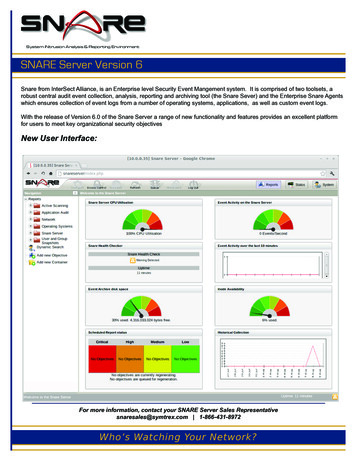
3. Launch “SignalProcessorIP 1.0.exe”. The following dialog box should appear.4. Confirm the connection indicator at the bottom of the dialog is GREEN. If theindicator is RED then the PC and Signal Processor are not communicating.5. Enter the desired IP address into the “New IP” field. Confirm “New Port” 23125and click the “Set device IP/PORT” button.6. Confirm that you want to reset the device IP address.7. Close and restart “SignalProcessorIP 1.0.exe”. Confirm the new IP and correctport appears in the “Current IP” field.Regarding errors: Errors that occur after the “Set device IP/PORT button or closingthe program can be ignored. Always close and re-open SignalProcessorIP.exe toconfirm the new IP and port number are shown in the “Current IP” and “Current Port”fields whether errors occur or not.6
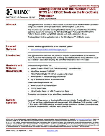
Signal Processor Firmware Version 2.01. Using a Windows based PC, retrieve the file named “SignalProcessorIP 2.0.exe”from the Arcom Labs FTP server located in the folder “/From Arcom/Public/QAMSnare/Clients”.2. Connect a USB port from the PC to the USB port on the back of the Headend SignalProcessor. Wait until the drivers automatically load.3. Launch “SignalProcessorIP 2.0.exe”. The following dialog box should appear.4. Confirm the connection indicator at the bottom of the dialog is GREEN. If theindicator is RED then the PC and Signal Processor are not communicating.5. Enter the desired IP and Subnet Mask in the “New settings” field. Confirm “Port” 23125 and click the “Set device IP/PORT” button.6. Confirm that you want to reset the device IP address.7
7. Close and restart “SignalProcessorIP 1.0.exe”. Confirm the new IP and correctport appears in the “Current IP” field.Regarding errors: Errors that occur after the “Set device IP/PORT button or closingthe program can be ignored. Always close and re-open SignalProcessorIP.exe toconfirm the new IP and port number are shown in the “Current IP” and “Current Port”fields whether errors occur or not.Port UsageThe diagram below details the internet socket port numbers used forcommunication between various QAM Snare devices.8
Headend Signal Processor port numberThe Headend Signal Processor requires port 23125 to be open.QAM Snare Server port numberThe QAM Snare Server requires ports 23125, 23126, 22, and 80 to be open.Setting the QAM Input LevelsThe recommended method of setting an HSP QAM input level is to use the “HUB ADC Data”screen in QS Manager, displaying the Time Domain or the “Oscilloscope” view. Usingattenuators adjust the HSP QAM input level for the channel of interest so the voltage responseis between 0.20 and 0.80V Pk.To illustrate the correct level setting, the pictures below show one ADC input at 0.2V Peak,one at 0.8V Peak, and one slightly above 1.0V Peak. Keeping the peaks between 0.2V and 0.8Volts is correct, anything over 0.8 Volts is incorrect. The peaks are marked by the dashed lines.9
Server Configuration/LocationThe QAM Snare Server requires a static IP address or alternatively dynamic DNS.Multi-hub environmentIn a multi-hub environment, the QAM Snare Server can be either physically locatedin one hub, a company data center, or it can be cloud based. The Server and allHeadend Signal Processors require their own IP connections.Single hub environmentFor a single hub installation, the Headend Signal Processor may connected usingany of the following configurations:1) Directly by a cable to the second Ethernet port of the server. One server port isused for communication with the Headend Signal Processor, and the second isused for the server connection to Internet (external IP). In this configurationthe Headend Signal Processor should be assigned IP 192.168.1.XXX.2) To LAN of the hub where Headend Signal Processor and server is installed. Inthis case the server will communicate from a single Ethernet port via LAN toboth the Headend Signal Processor and Internet.3) Directly to Internet just like in the multi-hub environment, with the HeadendSignal Processor having its own IP address. This solution is least desirable sincetwo IP addresses are required.Headend Signal Processor size, voltage, power specificationsQSNARE-SP-4 Input Voltage 115 – 230 VAC, 50/60 HzQSNARE-SP-4-48V Input Voltage -48.0 VDCPower 40 Watts max during normal operation.Size 1-up 19” Rack MountedDimensions 19”W X 1-3/4”H X 9”DQAM input 0 to -20dBmV, 75 Ohms10
1. Using a Windows based PC, retrieve the file named “SignalProcessorIP_1.0.exe” from the Arcom Labs FTP server located in the folder “/From Arcom/Public/QAM Snare/Clients”. 2. Connect a USB port from the PC to the USB port on t