Transcription
NASA/TM-1998-206561Linear Aerospike SR-71 Experiment(LASRE): Aerospace Propulsion HazardMitigation SystemsMasashi Mizukami, Griffin P. Corpening,Ronald J. Ray, Neal Hass, and Kimberly A. EnnixDryden Flight Research CenterEdwards, CaliforniaScott M. LazaroffNASA Johnson Space CenterHouston, TexasJuly 1998
The NASA STI Program Office . . . in ProfileSince its founding, NASA has been dedicatedto the advancement of aeronautics and spacescience. The NASA Scientific and TechnicalInformation (STI) Program Office plays a keypart in helping NASA maintain thisimportant role.The NASA STI Program Office is operated byLangley Research Center, the lead center forNASA’s scientific and technical information.The NASA STI Program Office provides accessto the NASA STI Database, the largest collectionof aeronautical and space science STI in theworld. The Program Office is also NASA’sinstitutional mechanism for disseminating theresults of its research and development activities.These results are published by NASA in theNASA STI Report Series, which includes thefollowing report types: TECHNICAL PUBLICATION. Reports ofcompleted research or a major significantphase of research that present the results ofNASA programs and include extensive dataor theoretical analysis. Includes compilationsof significant scientific and technical dataand information deemed to be of continuingreference value. NASA’s counterpart ofpeer-reviewed formal professional papers buthas less stringent limitations on manuscriptlength and extent of graphic presentations.TECHNICAL MEMORANDUM. Scientificand technical findings that are preliminary orof specialized interest, e.g., quick releasereports, working papers, and bibliographiesthat contain minimal annotation. Does notcontain extensive analysis.CONTRACTOR REPORT. Scientific andtechnical findings by NASA-sponsoredcontractors and grantees. CONFERENCE PUBLICATION.Collected papers from scientific andtechnical conferences, symposia, seminars,or other meetings sponsored or cosponsoredby NASA. SPECIAL PUBLICATION. Scientific,technical, or historical information fromNASA programs, projects, and mission,often concerned with subjects havingsubstantial public interest. TECHNICAL TRANSLATION. Englishlanguage translations of foreign scientificand technical material pertinent toNASA’s mission.Specialized services that complement the STIProgram Office’s diverse offerings includecreating custom thesauri, building customizeddatabases, organizing and publishing researchresults . . . even providing videos.For more information about the NASA STIProgram Office, see the following: Access the NASA STI Program Home Pageat http://www.sti.nasa.gov E-mail your question via the Internet tohelp@sti.nasa.gov Fax your question to the NASA Access HelpDesk at (301) 621-0134 Telephone the NASA Access Help Desk at(301) 621-0390 Write to:NASA Access Help DeskNASA Center for AeroSpace Information7121 Standard DriveHanover, MD 21076-1320
NASA/TM-1998-206561Linear Aerospike SR-71 Experiment(LASRE): Aerospace Propulsion HazardMitigation SystemsMasashi Mizukami, Griffin P. Corpening,Ronald J. Ray, Neal Hass, and Kimberly A. EnnixDryden Flight Research CenterEdwards, CaliforniaScott M. LazaroffNASA Johnson Space CenterHouston, TexasNational Aeronautics andSpace AdministrationDryden Flight Research CenterEdwards, California 93523-0273July 1998
NOTICEUse of trade names or names of manufacturers in this document does not constitute an official endorsementof such products or manufacturers, either expressed or implied, by the National Aeronautics andSpace Administration.Available from the following:NASA Center for AeroSpace Information (CASI)7121 Standard DriveHanover, MD 21076-1320(301) 621-0390National Technical Information Service (NTIS)5285 Port Royal RoadSpringfield, VA 22161-2171(703) 487-4650
LINEAR AEROSPIKE SR-71 EXPERIMENT (LASRE):AEROSPACE PROPULSION HAZARD MITIGATION SYSTEMSMasashi Mizukami,* Griffin P. Corpening,† Ronald J. Ray,† Neal Hass,† Kimberly A. Ennix†NASA Dryden Flight Research CenterEdwards, CaliforniaScott M. Lazaroff†NASA Johnson Space CenterHouston, TexasAbstractA major hazard posed by the propulsion system ofhypersonic and space vehicles is the possibility of fire orexplosion in the vehicle environment. The hazard ismitigated by minimizing or detecting, in the vehicleenvironment, the three ingredients essential toproducing fire: fuel, oxidizer, and an ignition source.The Linear Aerospike SR-71 Experiment (LASRE)consisted of a linear aerospike rocket engine integratedinto one-half of an X-33-like lifting body shape, carriedon top of an SR-71 aircraft. Gaseous hydrogen andliquid oxygen were used as propellants. AlthoughLASRE is a one-of-a-kind experimental system, it mustbe rated for piloted flight, so this test presented a uniquechallenge. To help meet safety requirements, thefollowing propulsion hazard mitigation systems wereincorporated into the experiment: pod inert purge,oxygen sensors, a hydrogen leak detection algorithm,hydrogen sensors, fire detection and pod temperaturethermocouples, water misting, and control roomdisplays. These systems are described, and theirdevelopment discussed. Analyses, ground test, and flighttest results are presented, as are findings and aped pod, housingfluid and other systems in LASREGH2gaseous hydrogenH2hydrogenH 2OwaterHeheliumLASRELinear Aerospike SR-71 ExperimentLN 2liquid nitrogenLO 2liquid oxygenmodeltop portion of LASRE, shaped like onehalf of a lifting bodyN2nitrogenO2oxygenPhydrogen tank pressure, psiP ambambient pressure, psiaP calibpressure during calibration, psiapsipounds per square inchpsiapounds per square inch, absolutepsigpounds per square inch, gageP SLsea level pressure, psiaRgas constantThydrogen gas temperature, RTEA-TEBtriethylaluminum-triethylboraneVhydrogen tank volume, in3Zcompressibility m H*Aerospace Engineer, AIAA Member.†Aerospace Engineer.Copyright 1998 by the American Institute of Aeronautics andAstronautics, Inc. No copyright is asserted in the United States underTitle 17, U.S. Code. The U.S. Government has a royalty-free licenseto exercise all rights under the copyright claimed herein for Governmental purposes. All other rights are reserved by the copyright owner.2change in mass of hydrogen in tanks, lbm%H 2volume fraction of hydrogen%H 2volume fraction of hydrogen, measuredmeas%O 2volume fraction of oxygen%O 2volume fraction of oxygen, measuredmeas1American Institute of Aeronautics and Astronautics
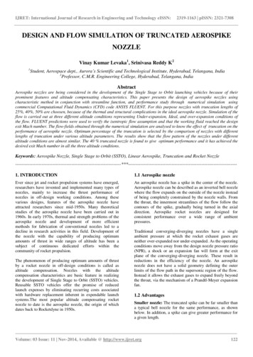
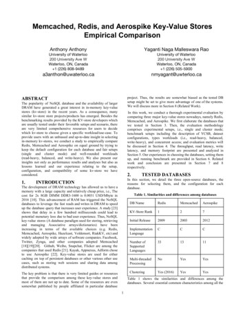
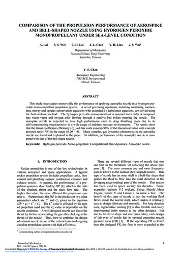
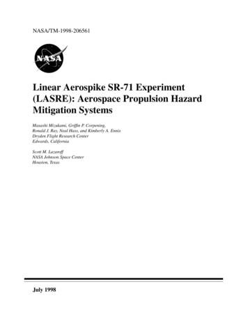
Introductionpropulsion concept done in cooperation with theindustry. NASA Dryden Flight Research Center,Edwards, California was responsible for the flight test.3The experiment consisted of a linear aerospike rocketengine integrated into one-half of an X-33-like liftingbody shape, carried on top of an SR-71 aircraft (figs. 1,2). Unlike conventional bell nozzle rockets, the linearaerospike engine can compensate for ambient backpressure effects to provide higher performance over awide range of altitudes. However, external flowslipstream effects on the nozzle flow may reduceperformance. Therefore, the primary objective ofLASRE was to evaluate flight effects on aerospikeengine performance at several altitudes and Machnumbers. Although LASRE is a one-of-a-kindexperimental system, it had to be rated for piloted flight,which demands a high degree of safety. A rapidprototyping approach was taken to hardwaredevelopment. This approach resulted in an extendedseries of tests to troubleshoot and validate the integratedsystem. These tests included various functional testssuch as ‘cold flows’ of inert fluids, ‘ignition tests’ usingLO 2 and triethylaluminum-triethylborane (TEA-TEB),and actual ‘hot fires’ of the engine.For hypersonic and space vehicles that are reusableor piloted, safety is an exceptionally importantconsideration. For piloted vehicles, this consideration isa result of the possible tragic consequences of a mishap.For reusable launch vehicles, cost is the major driver;the total operational costs must be minimized, includingthe high cost of losing an expensive vehicle and itspayload as a result of a mishap. For a flight researchproject, safe flight can be considered as important as thetechnology being investigated.A major hazard posed by the propulsion system ofhypersonic and space vehicles is the possibility of a fireor explosion in the vehicle environment. These systemsstore a large amount of potential energy in the form offuel, oxidizer, high pressures or a combination ofthese.1,2 The three ingredients essential to theproduction of fire are fuel, oxidizer, and an ignitionsource (except in the case of hypergolics andpyrophorics, which can combust without an ignitionsource). Minimizing or detecting those three ingredientsin the vehicle environment mitigates the hazard. Inaddition to sound design and operational practices, it isoften necessary to provide dedicated hazard mitigationsystems.A simplified schematic of fluid systems in the LASREpod is shown in figure 3. Essentially, this was a flyingrocket engine test facility. The model is the top portionshaped like half of a lifting body. The canoe is anThe Linear Aerospike SR-71 Experiment (LASRE) isa flight experiment of a reusable launch vehicle980345Figure 1. LASRE configuration mounted on SR-71 aircraft.2American Institute of Aeronautics and Astronautics
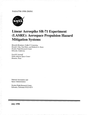
EC 97-44295-108Figure 2. SR-71 and LASRE in flight.ModelCanoeHe He HePod cooling H2OHeEngine cooling H2OGH2GH2HeHeTEATEBEngineLO2GH2SR-71Purge LN2980346Figure 3. Simplified schematic of LASRE fluid systems.in the engine block and out the water exit line. Two 9000psi gaseous helium (He) systems provided LO 2pressurant, water pressurant, line purges, TEA-TEBcartridge expulsion and pneumatic valve actuation. TheSR-71 contained water for pod misting, and liquidnitrogen ( LN 2 ) for pod inert purge.aerodynamically-shaped pod, housing several fluid (andother) systems. A 4000 psi gaseous hydrogen ( H 2 )blowdown system, containing about 20 lb of H 2 ,provided fuel to the engine. A liquid oxygen ( LO 2 )system, containing about 330 lb of LO 2 , andpressurized to about 365 psi, provided the oxidizer. BothH 2 and LO 2 could be dumped overboard through theengine. H 2 could also be expelled overboard throughdump lines, and LO 2 pressure could be releasedthrough a vent line. Triethylaluminum-triethylborane(TEA-TEB), a pyrophoric, was used to initiatecombustion in the engine. Engine coolant water,pressurized to 800 psi, flowed through channels drilledEven before hazard mitigation systems wereincorporated, the soundness of the underlyingpropulsion system itself had to be assured. The systemwas intended to be fail-safe for single-point failures.Component burst and proof factors were equal to orgreater than those used in typical missile and space3American Institute of Aeronautics and Astronautics
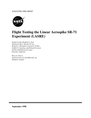
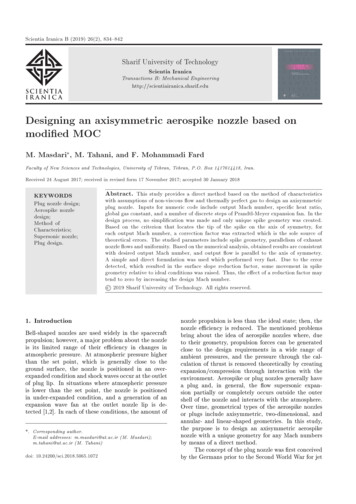
systems.4 The H 2 and LO 2 systems were leak checkedas much as was feasible on the integrated pod, usinglong-term pressure decay, bubble fluid, an ultrasonicleak detector, a thermal conductivity leak detector, anelectrochemical hydrogen sensor, and blowdown testing.test results are presented, as are findings and lessonslearned. Use of trade names or names of manufacturersin this document does not constitute an officialendorsement of such products or manufacturers, eitherexpressed or implied, by the National Aeronautics andSpace Administration.Flammability limits for H 2 - O 2 - N 2 mixtures at sealevel are about 4 percent H 2 and 4 percent O 2 , and arefairly independent of each other (fig. 4). The limitsremained about the same throughout the LASRE flightenvelope, extending up to an altitude of 50,000 ft, andwere not significantly narrowed by reduced pressures atthose altitudes.5 Calculation of combustion conditionsat equilibrium or for detonation showed that even forlow flammable concentrations of H 2 and O 2 ,temperatures and pressures high enough for catastrophicconsequences could develop. Therefore, a ground rulewas established that O 2 and H 2 concentrations in thepod should be maintained below 4 percent during theentire mission, because any combustion in the pod wasconsidered unacceptable.Propulsion Hazard Mitigation SystemsThe following sections discuss the systems andmethods used to mitigate propulsion hazards. Findingsand lessons learned as a result of tests performed arealso presented.Pod Inert PurgeThe pod cavity was purged with inert N 2 gas, forseveral reasons. The primary purpose was to minimizethe presence of oxidizer in the pod environment tobelow 4 percent O 2 by displacing air out of the pod.The purge may also reduce the presence of fuel bydisplacing any leaked H 2 . The H 2 and LO 2 valves andsome of the electronics boxes were purged with N 2 , tominimize ignition sources. This purge surrounded theelectronics with inert gas, and prevented moisturecaused by water misting from coming into contact withthe electronics.To help meet safety requirements, propulsion hazardmitigation systems were incorporated in LASRE. Thesesystems were: a pod inert purge, O 2 sensors, a H 2 leakdetection algorithm, H 2 sensors, fire detection and podtemperature thermocouples, water misting, and controlroom displays. These systems are described, and theirdevelopment discussed. Analyses, ground test, and flightFigure 5 shows a schematic of the N 2 purge system.N 2 was supplied from two LN 2 Dewar flasks onboard01009010802070306040Flammable regionN2 concentration,percent volume 50O2 concentration,percent volume50406030702080Air10900Nonflammable region1000102030405060H2 concentration, percent volume7080Figure 4. Flammability limits of H 2 – O 2 – N 2 mixtures at sea level.4American Institute of Aeronautics and Astronautics90100980347
Figure 5. Nitrogen purge system schematic.5American Institute of Aeronautics and Astronautics
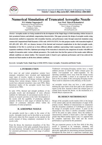
the SR-71. LN 2 was vaporized by electric heaters, itwas dispersed into the pod through perforated piccolotubes near the front of the pod, and also into theelectronics boxes and valves. The two Dewar flasks helda total of 100 liters (180 lb) of LN 2 . The flow rate wasabout 2.5 lb/min, or 34 standard cubic feet per minute,for an operating duration of 72 minutes. These flowrates gave about 0.3 volume change-outs per minute onthe ground, and 2.4 change-outs per minute at analtitude of 50,000 ft. For ground operations, N 2 wasdirectly provided from a ground cart to conserve theonboard LN 2 supply. During flight, flow could beturned on or off from the SR-71 rear cockpit, and theoperating pressure was monitored in the control room toverify flow.decreased, and pod pressure was maintained aboveambient pressure, which aided purge effectiveness.However, during descent the opposite effect occurred,which made it difficult to maintain an adequate purge.These tests demonstrated that it is important to providean adequate purge flow rate, and to seal the vehicle wellagainst outside air infiltration.Oxygen SensorsTwelve oxygen sensors were located in the pod todetect the presence of oxidizer, eight in the canoe andfour in the model. The purpose of these sensors was todetermine inert purge effectiveness, infiltration ofoutside air, and the presence of any leaked LO 2 .Commercially available electrolytic sensors were used,originally intended for automotive applications. Eachsensor was installed in a temperature-controlled canisterwhich was heated to about 115 F, to reduce effects ofambient temperature changes on the readings. Thesesensors were point measurements that would not detectair or oxygen which could have been trapped in otherareas, but the number and distribution of the sensorswere judged sufficient to characterize overall O 2 levelsin the pod.Purge effectiveness was evaluated primarily by usingO 2 sensors distributed in the pod. Preliminary groundtesting revealed that it took a long time to establish apurged environment, and the pod panels had to be wellsealed to maintain it. Therefore, a separate monsterpurge was implemented to establish an initially purgedenvironment by using ground service equipment that fedlarge quantities of N 2 directly into the pod. Duringsubsequent ground tests an adequate purge wasconfirmed. In flight however, substantial infiltration ofexternal air occurred shortly after takeoff and purgeeffectiveness was quickly lost, with O 2 levels reachingnearly 21 percent. Therefore, attempts were made toseal gaps in the pod by using elastic materials such asfoam rubber and caulking. Also, the second LN 2 Dewarflask was added, and purge flow rate was doubled tocurrent levels (2.5 lb/min). In addition, a valve wasplaced in the purge vent line, which could be remotelyactuated from the cockpit. With the valve open, thepurge gas flowed through the pod and out the vent asoriginally designed, which also allowed any major leaksto be vented out of the pod. With the valve closed, thepurge gas maintained a positive pressure in the pod, thusreducing air infiltration. The purge gas flowed out fromany remaining leak paths. A subsequent flight testdemonstrated adequate purge performance for flight, upto about Mach 0.9 and an altitude of 26,000 ft, with O 2levels below 4 percent. Figure 6 shows Mach number,altitude, and the measured O 2 levels during a portion ofthe flight. The canoe O 2 sensor that reads consistentlylow O 2 levels is located close to a purge piccolo tubenear the front of the canoe. The spike above 4 percent isbelieved to be telemetry noise. A preliminaryassessment of additional data suggested that purgeintegrity may be maintained up to Mach 1.6 and analtitude of 50,000 ft. It was observed that with the ventvalve closed, pressure was maintained in the pod duringclimb and descent. During climb, ambient pressureIt was evident from data at altitude that these sensorsactually measured the partial pressure of O 2 , butvolume fraction is of greater interest than partialpressure for determining the flammability of mixtures.Therefore, volume fraction of O 2 ( %O 2 ) wascalculated by correcting the measured partial pressureof O 2 ( %O 2) to sea level pressure ( P SL ), usingmeasambient pressure ( P amb ), as follows:%O 2 % O 2measP SL-----------P amb(1)Accuracy of the sensor at sea level, according to thespecification sheet, was 1 percent. But for a givenvolume fraction of O 2 , as altitude increased, ambientpressure decreased, and the partial pressure of O 2decreased, approaching sensor accuracy limits. As aresult, at high altitudes O 2 volume fraction determinedfrom sensor readings appeared erratic.A test program was undertaken to better characterizesensor accuracy at altitude. In a small test chamber,sensors were exposed to a range of O 2 concentrationsvarying from 0 percent to 21 percent, at a range ofpressure altitudes from sea level to 80,000 ft. Becausesensors have a life of about 2 years, new sensors as wellas older ones were tested to help determine aging6American Institute of Aeronautics and Astronautics
1.0.8.6Mach.4.2030 x 10 32520Altitude, 15ft105010CanoeO2 sensors86% O242010ModelO2 sensors86% O242010.010.5Time, sec11.0 x 10 3980349Figure 6. Nitrogen purge effectiveness in flight, from takeoff up to Mach 0.9 and an altitude of 26,000 ft.7American Institute of Aeronautics and Astronautics
effects. Representative results for 0 percent, 1 percent,2 percent and 5 percent O 2 concentrations are shown infigure 7(a). Accuracy at sea level appears much betterthan the specified 1 percent accuracy, but a distinctdrop-off is seen above an altitude of 30,000 ft. Tocompensate for the drop-off, a fifth-order polynomialcorrection was applied to the average of the sensorreadings (fig. 7(b)). Ninety-nine percent confidenceintervals for the corrected readings, based on thet-distribution, were less than 1.3 percent up to analtitude of 50,000 ft (fig. 7(c)).Hydrogen Pressure Decay Leak DetectionIn order to infer the presence of fuel in the pod, areal-time pressure-decay method was used to detectleaking hydrogen. Conventionally, pressure-decay leakdetection takes a long time to perform, and is doneduring system checkout. A noticeable pressure drop inthe gaseous hydrogen tanks during flight operationwould indicate a large leak, or perhaps a thermaltransient. However, as a result of the unavailability ofhydrogen sensors, a pressure-decay method wasimplemented for real time in-flight use. It was fordetection of leaks from the H 2 tanks in a static modeonly, and not for detection of leaks in the H 2 lines orduring flow.Rules were established for interpreting and acting onO 2 sensor data during flight. If any O 2 sensor, plus itsuncertainty, exceeded a specified threshold level(nominally 4 percent), steps would be taken to securethe system and mitigate the hazard, typically bydumping the H 2 overboard.In theory, the hydrogen tank leak rate can bedetermined from the change in mass of hydrogen in thetanks ( m H ) as follows:2P0V P m H ---- ------- – ------------- 2R ZT Z 0 T 0 Clearly, it was important to validate O 2 sensoraccuracy before use, especially because these sensorswere being used outside their originally intendedenvironment. Characteristics of other types of sensors,or sensors from other manufacturers, might be entirelydifferent.Tank pressure (P) was measured by a pressuretransducer. Hydrogen gas temperature (T) was measuredby two redundant thermocouples mounted on probes8Sensor123456765% O24321010(2)203040Pressure altitude, ft5060 x 10 3980350(a) Pressure altitude compared with percent O 2 , for 5 percent, 2 percent, 1 percent and 0 percent O 2 mixtures.Figure 7. Oxygen sensor altitude chamber test data.8American Institute of Aeronautics and Astronautics
8Sensor123456765% O2fifth order 4correction321010203040Pressure altitude, ft5060 x 10 3980351(b) Pressure altitude compared with percent O 2 with fifth order correction, for 5 percent, 2 percent, 1 percent and0 percent O 2 mixtures.2.0Sensor1251.5% O21.0uncertainty.5010203040Pressure altitude, ft5060 x 10 3980352(c) Pressure altitude compared with 99 percent confidence intervals for 5 percent, 2 percent and 1 percent O 2 mixtures.Figure 7. Concluded.9American Institute of Aeronautics and Astronautics
inside the tanks, which were averaged together. Note,that to obtain an accurate measurement of gastemperature under changing conditions, a tank surfacemeasurement would have been inadequate. Tank volume(V) was assumed to be constant. Compressibility (Z)was a function of P and T, and the subscript 0 denotesinitial conditions. R is the gas constant for H 2 .the minimum leak rate reliably detectable in areasonable timeframe. However, this is still a substantialand potentially hazardous quantity of hydrogen that iscapable of locally forming combustible mixtures in thepod. Lower leak rates could possibly be detected over alonger period of time.The H 2 leak detection algorithm was a useful tooland was the only available means of H 2 leak detectionon LASRE, but could not be relied upon to detect allhazardous leaks. This algorithm could detect moderateto large tank leaks, or smaller leaks over a long period oftime. However, it could not detect small but stillhazardous leaks in a timely manner, nor did it detectleaks in the H 2 lines.In software, digital low-pass filtering was applied tothe m H signal, to remove high frequency random2noise, and to facilitate data interpretation. The filter timeconstant was adjustable, and was set by the user to obtaina readable signal, while preserving reasonable responsetime and quick recovery from data spikes. Magnitudelimits were imposed to prevent telemetry data spikesfrom corrupting the calculation. The calculation could beconfigured for either hydrogen or inert helium as theworking gas. The resulting m H signal was displayed2on a scrolling time history display (fig. 8).Hydrogen SensorsAlthough H 2 sensors were not used, they would haveconstituted a more direct way to detect the presence offuel. Sensors were planned to be strategically positionedwithin the canoe and model. The sensor proposed foruse was based upon a design developed by SandiaNational Laboratories, Albuquerque, New Mexico.6 Thesensor element was a Palladium-Nickel patch that has acurrent passing through it. When present, hydrogenfreely infiltrates the lattice network of the crystal,causing a change to the electrical resistance of theelement proportional to the local concentration. Theelement was temperature regulated by a controller,which aided in the response time of the sensor andremoved one of the operational variables. Theadvertised range of detection was 1 percent to100 percent volume fraction, with 0.5 percent accuracy.The ability to detect leaks depended on discerningsmall changes in pressure and temperature, which was afunction of instrumentation accuracy. The trace showedgood stability under the varying ambient conditions offlight. Uncertainty analysis indicated that a mass loss of0.15 lb or more could be detected. Ground testing, doneby releasing controlled small amounts of gas from thetanks and observing the trace, showed that mass loss aslow as 0.03 lb could be detected.In the control room, if a mass loss rate of greater than0.03 lb was seen in 8 minutes or less, it would beconsidered a positive determination of leakage, andsteps would be initiated to secure the system bydumping propellants overboard. This leak ratecorresponds to about 4 percent of the N 2 purge flow ratein the vicinity of the H 2 tanks, or about 1460 standardcubic inches per minute. This amount was judged to beThe suitability and accuracy of the sensor in a flightenvironment needed to be ascertained. A test chamberwas used to simulate pressure altitudes. Testing wasconducted with pure N 2 and with calibration gases ofspecific concentrations of H 2 in N 2 , at discrete ambient.05Current time mH0,2lb– .05– .10051015Time, min2025Figure 8. Hydrogen tank leak detection algorithm scrolling time history plot display.10American Institute of Aeronautics and Astronautics30980353
pressure points ranging from 2 psia to 13.5 psia. Thesensor heating element mitigated temperature effects.Results of applying this simple correction to the rawdata are shown in figure 9(b). Stable readings were seenup to nearly 27,000 ft pressure altitude. Deviation from3 percent actual concentration indicates a bias error, butit was believed this could be corrected with a morerigorous calibration program. Above an altitude of27,000 ft, the accuracy limitation of the sensor isreflected in the nonlinear deviation and data scatter. Verysimilar results where achieved using a 10 percent H 2concentration.Preliminary data for seven sensors with a 3 percentH 2 concentration by volume are shown in figure 9(a). Itis clear from the data that when the ambient pressurewas reduced the sensor measured concentration wasalso lowered and a linear relationship existed betweenambient pressures and the measured concentration.Therefore, the H 2 sensors appear to measure partialpressure of the gas to be detected, much like the O 2sensors. If this phenomenon was not accounted for, andthe sensor readings ( %H 2) were used withoutmeascorrection during flight, the readings could potentiallylead to the false conclusion that the flammability limitshad not yet been reached. Like the O 2 sensors, thefollowing correction algorithm could be applied realtime during flight using ambient pressure measurements( P amb ) in the pod and the pressure at which the sensorswere calibrated ( P calib ), to obtain percent volume ofhydrogen ( %H 2 ) present.%H 2 %H 2measP calib-------------P ambUnfortunately, once installed in the pod, the systemcould not be made to function correctly, apparentlybecause of design flaws in the H 2 sensor controller.Programmatic and schedule constraints ruled out thepossibility of troubleshooting to correct the system, sothe H 2 sensors were not installed for flight.Certainly, a H 2 detection system would be highlydesirable for hazard mitigation. Bench test results werepromising for future flight applications. However, H 2sensors and systems that are qualified for use in inertbackground, with varying pressures and temperaturesand that are robust and compact enough for flightapplication are difficult to find.7,8 H 2 detectiontechnologies can be pursued for future projects, as thistype of fuel becomes more prevalent.(3)8Sensor1234567765% H2meas 4321010203040Pressure altitude, ft5060 x 10 3980354(a) Pressure altitude compared with percent H 2 measured, for 3 percent H 2 mixture.Figure 9. Hydrogen sensor altitude chamber test data.11American Institute of Aeronautics and Astronautics
8Sensor1234567765% H24321010203040Pressure altitude, ft60 x 10 350980355(b) Pressure altitude compared with percent H 2 , for 3 percent H 2 mixture.Figure 9. concluded.Fire Detection and Pod Temperature Thermocoupleswould have been depressurized by dumping the contentsoverboard.Fifteen thermocouples were distributed throughoutthe pod for sensing heat from nearby combustion.Thermocouples are commonly used for local firedetection. Procedurally, if high temperatures that werefar above expected ambient total temperatures wereseen (especially locally), fire would be indicated andsteps would be taken to dump the propellants and securethe aircraft.Water Misting and Coolant SystemThe coolant water system was used to provide acooling water mist for the pod, and to recirculatecoolant for the electronics. The recirculating coolantwas required anytime the pod was powered up. The mistwas to be turned on only when necessary andappropriate for pod cooling, such as during highstagnation temperature flight conditionsThe thermocouples were also used to monitor podenvironment temperatures, because certain componentswere temperature limited, such as the composite H 2tanks and electronics. Flight data (fig. 10) showed that,except for some areas near cryogenic components, thepod thermal environment was quite benign throughoutthe
The experiment consisted of a linear aerospike rocket engine integrated into one-half of an X-33-like lifting body shape, carried on top of an SR-71 aircraft (figs. 1, 2). Unlike conventional bell nozzle rockets, the linear aerospike engine can compensate for ambient back-pressure effects to provide higher performance over a wide range of .