Transcription
NASA/TM-1998-206561Linear AerospikeSR-71 Experiment(LASRE):Aerospace PropulsionHazardMitigationSystemsMasashi Mizukami, Griffin P Corpenmg,Ronald J. Ray, Neal Hass. and Kimberly A. EnnixDryden Flight Research CenterEdwards, CaliforniaScott M. LazaroffNASA Johnson Space CenterHouston, TexasNationalAeronauticsandSpace AdministrationDryden Flight Research CenterEdwards, California 93523-0273July1998
NOTICEUse of trade names or names of manufacturersin this documentof such productsexpressedor manufacturers,eitherdoes not constituteor implied,an officialby the NationalendorsementAeronauticsandSpace Administration.AvailableNASA Center for AeroSpace7121 Standard DriveHanover, MD 21076-1320(301) 621-0390Informationfrom the e(NTIS)5285 Port Royal RoadSpringfield, VA 22161-2171(703) 487-4650
ffin E Corpening, t Ronald J Ray, Neal Hass, T KimberlyNASA Dryden Flight Research CenterEdwards, CaliforniaA Ennix TScott M. Lazaroff TNASA Johnson Space CenterHouston, TexasH20waterHeheliumLASRELinear AerospikeLN 2liquid nitrogenLO 2liquid oxygenmodeltop portionAbstractA major hazard posed by the propulsionsystem ofhypersonic and space vehicles is the possibility of fire orexplosionin the vehicle environment.The hazard ismitigatedby minimizingor detecting,in the roducingfire: fuel, oxidizer, and an ignition source.The LinearAerospikeSR-71 Experiment(LASRE)consisted of a linear aerospike rocket engine integratedinto one-half of an X-33-1ike lifting body shape, carriedon top of an SR-71 aircraft. Gaseous hydrogenandliquidoxygenwere used as propellants.AlthoughLASRE is a one-of-a-kindexperimentalsystem, it mustbe rated for piloted flight, so this test presented a uniquechallenge.To help meetsafety requirements,thefollowingpropulsionhazard mitigationsystems wereincorporatedinto the experiment:pod inert purge,oxygen sensors, a hydrogen leak detection algorithm,hydrogensensors, fire detection and pod temperaturethermocouples,watermisting,and controlroomdisplays.Thesesystemsare described,and theirN 2nitrogen0 2oxygenpod, housingfluid and other systemsGH ibpressureduringpsipoundspsiapounds per squareinch, absolutepsigpounds per squareinch, gagePSLsea level pressure,psiaRgas oraneVhydrogenZcompressibilityin LASREhydrogenAerospaceEngineer,Engineer.Copyright Astronautics,Titleto17, U.S.therightsInstituteis assertedGovernmentcopyrightare reservedofin calibration,per squarepsiainchgas temperature,tank volume,Rin 3in mass of hydrogen%H 2volumefractionof hydrogen%H2measvolumefractionof hydrogen,%02volumefractionof oxygen 02,neasvolumefractionof n tanks,measuredundera royalty-freeclaimedtank pressure,changeAmHTAerospaceshaped like one-PNomenclatureaerodynamically-shapedof LASRE,half of a lifting bodydevelopmentdiscussed. Analyses, ground test, and flighttest results are presented,as are findings and lessonslearned.canoeSR-71 ExperimentInstituteof AeronauticsandAstronauticsmeasuredIbm
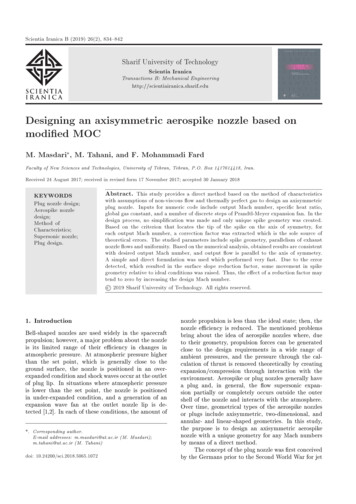
propulsionconceptdone in cooperationwith , California was responsiblefor the flight test. 3IntroductionFor hypersonicand space vehicles that are reusableor piloted,safetyis an exceptionallyimportantconsideration.For piloted vehicles, this considerationisa result of the possible tragic consequencesof a mishap.For reusable launch vehicles, cost is the major driver;The experimentconsistedof a linearaerospikerocketengine integratedinto one-half of an X-33-1ike liftingbody shape, carried on top of an SR-71 aircraft (figs. 1,2). Unlike conventionalbell nozzle rockets, the linearthe total operationalcosts must be minimized, includingthe high cost of losing an expensivevehicle and itspayload as a result of a mishap. For a flight researchproject, safe flight can be considered as important as thetechnology being investigated.aerospikeengine can compensatefor ambientbackpressure effects to provide higher performanceover awiderangeof altitudes.However,externalflowA major hazard posed by the propulsionsystem ofhypersonic and space vehicles is the possibility of a fireor explosion in the vehicle environment.These systemsstore a large amount of potential energy in the form offuel, oxidizer,high pressuresor a to theproductionof fire are fuel, oxidizer, and an ignitionsource(exceptin thecaseof hypergolicsandpyrophorics,which can combust without an ignitionsource). Minimizingor detecting those three ingredientsin the vehicle environmentmitigatesthe hazard. Inaddition to sound design and operationalpractices, it isoften necessary to provide dedicated hazard eameffects on the nozzleflow may reduceperformance.Therefore,the primaryobjectiveofLASREwas to evaluateflight effects on lopment.This approachresulted in an extendedseries of tests to troubleshootand validate the integratedsystem. These tests included various functionaltestssuch as 'cold flows' of inert fluids, 'ignition tests' usingLO 2 and triethylaluminum-triethylboraneand actual 'hot fires' of the engine.shapedlikehalfof a lifting9803451. LASREconfigurationmountedon SR-71 aircraft.2AmericanInstitute(TEA-TEB),A simplified schematic of fluid systems in the LASREpod is shown in figure 3. Essentially,this was a flyingrocket engine test facility. The model is the top portionThe Linear Aerospike SR-71 Experiment(LASRE) isflight experimentof a reusablelaunchvehicleFigurealtitudesand Machis a one-of-a-kindexperimentalsystem, it had to be rated for piloted flight,which demandsa high degree of safety. A rapidsystems.aat severalLASREof Aeronauticsand Astronauticsbody.Thecanoeis an
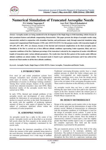
EC 97-44295-108Figure 2. SR-71 and LASREin flight.EngineCanoe((Pod((-\-(Enginecooling H20)(GH 2)(cooling H20 )GH 2'"")(GH 2I)SR-719803461Purge LN 2)Figureaerodynamically-shapedother)systems.A 4000pod, housingpsi gaseous3. Simplifiedseveralschematicfluid (andhydrogenof LASREfluid systems.in the engine block and out the water exit line. Two 9000(H2)psi gaseoushelium(He)systemsprovidedLO 2pressurant,water pressurant,line purges,TEA-TEBcartridge expulsion and pneumaticvalve actuation. Theblowdownsystem,containingabout 20 lb of H 2,providedfuel to the engine. A liquid oxygen (LO2)system,containingabout330 lb of L02,andpressurized to about 365 psi, provided the oxidizer. BothSR-71nitrogenH 2 and LO 2 could be dumped overboard through theengine. H 2 could also be expelled overboard throughcontainedwaterfor podmisting,andliquid(LN 2 ) for pod inert purge.dump lines, and LO 2 pressurecould be releasedthrougha vent line. Triethylaluminum-triethylborane(TEA-TEB),a pyrophoric,wasusedto initiatecombustionin the ingpropulsion system itself had to be assured. The systemwas intended to be fail-safe for single-pointfailures.Componentburst and proof factors were equal to orpressurizedgreaterto 800 psi, flowed f Aeronauticsand Astronauticsusedin typicalmissileandspace
test results are presented,as are findings and lessonslearned. Use of trade names or names of manufacturersin this documentdoesnot constitutean officialsystems. 4 The H 2 and LO 2 systems were leak checkedas much as was feasible on the integratedpod, usinglong-termpressure decay, bubble fluid, an ultrasonicleak detector, a thermal conductivityleak detector, anelectrochemicalhydrogensensor, and blowdownendorsementexpressed or implied,Space Administration.testing.Flammabilitylimits for H 2 - 0 2 - N 2 mixtures at sealevel are about 4 percent H 2 and 4 percent 02, and arefairly independentof each other (fig. 4). The limitsremained about the same throughout the LASRE flightenvelope, extending up to an altitude of 50,000 ft, andwere not significantlynarrowed by reduced pressures atthose altitudes. 5 Calculationof combustionconditionsPropulsionor manufacturers,by the sThe followingsectionsdiscussthe systemsandmethods used to mitigate propulsionhazards. Findingsand lessons learned as a result of tests performedarealso presented.at equilibriumor for detonationshowed that even forlowflammableconcentrationsof H 2 and02,temperaturesand pressures high enough for catastrophicconsequencescould develop. Therefore,a ground rulePod Inert PurgeThe pod cavity was purged with inert N 2 gas, forseveral reasons. The primary purpose was to minimizewas establishedthat 02 and H 2 concentrationsin thepod should be maintainedbelow 4 percent during theentire mission, because any combustionin the pod wasconsidered unacceptable.To help meet safety requirements,mitigation systems were incorporatedof such productsthe presenceof oxidizerin the pod environmenttobelow 4 percent 0 2 by displacingair out of the pod.The purge may also reduce the presenceof fuel bydisplacing any leaked H 2. The H 2 and LO 2 valves andsome of the electronicsboxes were purged with N 2, tominimize ignition sources. This purge surroundedtheelectronicswith inert gas, and preventedmoisturecaused by water misting from coming into contact withthe electronics.propulsion hazardin LASRE. Thesesystems were: a pod inert purge, 02 sensors, a H 2 leakdetection algorithm, H 2 sensors, fire detection and podtemperaturethermocouples,water misting, and controlroom displays. These systems are described, and theirdevelopmentdiscussed. Analyses, ground test, and flightFigure5 shows a schematicN 2 was suppliedofrom twolOO90lOO4American Institute of Aeronautics and Astronauticsof the N 2 purge systemLN 2 Dewarflasks onboard
t, ']i'". ,s' ".-" /'"'".- - ,.,.,. 1--I "l'!LO 2I ' V l' '.oDE,: I/"I!,I EUECTRON CSI.Qm"2""'"TOU.!.u.- 11,- . z. . -I.IBOX JI, L ,.IIN-I 1VLJ L ]] L'V I. GASEOUS N 2PICCOLO INN 2I: I - .I ASEOU., I .,11I . o .o.I":--I TI,. -- ,cATFORWAIO-IFfl '-- c---' c-'P CCOLOI- i., ou. ROUNOCART.LL-- JLoENDOFCAN EtlIL 2L:(.GN 2 CONNECTIONiI3fFLOW CONTROLo., .INUMBERCHECK r----I.3 LN 2 SYSTEMTEXlSTING)VA V40 PSIG REUEF VALVE50 LITER LN 2 DEWARIIIFLOW CONTROLPRESSUREORIFICESWITCH TO COCKPIT/pRE.,W'--- ---f :----: U ,l('p--vo.o.A,PRE33UREiPRESSLOW UGHTTRANSDUCERFOR FLTPRESSURE TRANSDUCERS I TEST INSTRUMENTATIONIII HEATERIlt REF ENCEOTO, . E.,IT" 1. ATE.LSENSE PORTSFUELTANKFL% IT"O"(.,.y.y-FILL & VENT VALVE & FILTER-"--'.PRESSURE/-iJTO STREGULATORSOLENOIDVALVEGASIFIERPRE"I (TOCONTROLPANEL)LN2. @: VE.TTO.A*He KVALVELFMEBAY (K BAY)iumAUXILIARY LN2 SYSTEM40 PSIG REUEF VALVE50 LITER LN 2 DEWAR--.-J[PRESS. u i1VENT TO BAY4o PSIG RELIEF VALVE*"--- 'w,.o.,REFER CEO.OS.A.,ENTV T /I .E ERVALVEFLOT )IFILL & VENT VALVE & FILTERPRESSUREFigure REGULATOR5. NitrogenIIpurge system schematic.5AmericanInstituteof AeronauticsCHECKi Iand Astronautics980348
the SR-71. LN 2 was vaporizedby electric heaters, itwas dispersed into the pod through perforatedpiccolotubes near the front of the pod, and also into theelectronics boxes and valves. The two Dewar flasks helda total of 100 liters (180 lb) of LN 2. The flow rate wasabout 2.5 lb/min, or 34 standard cubic feet per minute,for an operating durationof 72 minutes. These flowrates gave about 0.3 volume change-outsper minute onthe ground,and 2.4 change-outsper minute at analtitude of 50,000 ft. For ground operauons,N 2 wasdirectly provided from a ground cart to conserve theonboardLN 2 supply. During flight, flow could beturned on or off from the SR-71 rear cockpit, and theoperatingpressurewas monitoredin the control room toverify flow.Purge effectivenesswas evaluatedprimarilyby using0 2 sensors distributedin the pod. Preliminarygroundtesting revealed that it took a long time to establish apurged environment,and the pod panels had to be wellsealed to maintainit. Therefore,a separate monsterpurge was implementedto establish an initially purgedenvironmentby using ground service equipment that fedlarge quantgiesof N 2 directly into the pod. Duringsubsequentgroundtestsan adequatepurgewasconfirmed.In flight however, substantialinfiltration ofexternalair occurredshortly after takeoff and purgeeffectivenesswas quickly lost, with 0 2 levels reachingnearly 21 percent. Therefore,attempts were made toseal gaps in the pod by using elastic materials such asfoam rubber and caulking. Also, the second LN 2 Dewarflask was added, and purge flow rate was doubled tocurrent levels (2.5 lb/min).In addition, a valve wasplaced in the purge vent line, which could be remotelyactuated from the cockpit. With the valve open, thedecreased,and pod pressurewas maintainedaboveambientpressure,whichaided purge effectiveness.However, during descent the opposite effect occurred,which made it difficult to maintain an adequate purge.These tests demonstratedthat it is important to providean adequate purge flow rate, and to seal the vehicle wellagainst outside air infiltration.OxygenSensorsTwelve oxygen sensors were locateddetect the presence of oxidizer, eight infour in the model. The purpose of thesedetermineinert purge effectiveness,outside air, and the presenceof any leakedLO 2.Commerciallyavailable electrolyticsensors were used,originally intended for automotiveapplications.Eachsensor was installed in a temperature-controlledcanisterwhich was heated to about 115 F, to reduce effects ofambient temperaturechangeson thesensors were point measurementsthatair or oxygen which could have beenareas, but the number and distributionwere judged sufficient to characterizealtitude, and the measured0 2 levels during a portion ofthe flight. The canoe 02 sensor that reads consistentlylow 0 2 levels is located close to a purge piccolo tubenear the front of the canoe. The spike above 4 percent isbelievedto be telemetrynoise.A preliminaryassessmentof additionaldata suggestedthat purgeintegrity may be maintainedup to Mach 1.6 and analtitude of 50,000 ft. It was observed that with the ventvalve closed, pressure was maintained in the pod duringclimb and descent.During climb, ambientpressurereadings. Thesewould not detecttrapped in otherof the sensorsoverall 0 2 levelsin the pod.It was evident from data at altitudemeasuredvolumefractionpressurefor determiningthe flammabilityvolumeofTherefore,calculatedof 0 2ambienttheispartialthat these sensorsactuallyof(%02 .pressurepressuregreaterfractionby correctingpurge gas flowed through the pod and out the vent asoriginally designed, which also allowed any major leaksto be vented out of the pod. With the valve closed, thepurge gas maintained a positive pressure in the pod, thusreducing air infiltration. The purge gas flowed out fromany remainingleak paths. A subsequentflight testdemonstratedadequate purge performancefor flight, upto about Mach 0.9 and an altitude of 26,000 ft, with 02levels below 4 percent. Figure 6 shows Mach number,in the pod tothe canoe andsensors was toinfiltrationofofinterest0 2the measured0 2 , butthanpartialof mixtures.(%0 2 )partial) to sea level pressure(Pamb)' as ication %02of the sensorsheet, was.(1)Pambat sea level, according to the1 percent.But for a givenvolume fraction of 0 2 , as altitude increased, ambientpressuredecreased,and the partial pressureof 0 2decreased,approachingsensor accuracylimits. As aresult, at high altitudes 0 2 volume fractionfrom sensor readings appeared erratic.determinedA test program was undertaken to better characterizesensor accuracy at altitude. In a small test chamber,sensorswere exposedvaryingfromto a range of 0 2 concentrations0 percentto 21 percent,at a rangeofpressure altitudes from sea level to 80,000 ft. Becausesensors have a life of about 2 years, new sensors as wellasolderoneswere6American Instituteof Aeronautics and Astronauticstestedto helpdetermineaging
1.0.8.6Mach.4iiiiiiiiiiii iiiiiiillL .j .2.,-,,,/ i0;;30 x 10 3Ii252OAltitude,ftiiiiiiiiiiiiiiiiiiiiiiiii ii!iii iiiiiiiiiii15.25i .t. /: . !. i.01086.i10Jii,,,Canoe,,,0 2 sensorsiiiiiir-.i- .ii .%0 242. ,';. .:- .- - .----,-- --'!.I .'0, . ".I?"---. ,.'. ,.,. .- .*- .j--. '., :.,b. ,. ,. .;-. . L ., ,', J;.,J--I10i86.%0 2420.IiiiiiittJitriiiiiiir-rJ.1.1t.i .iiiiitr.-. Ji--. . -.-.-.;:. .-ii10.0Model0 2 sensors:.:-,.i10.5Time, seci-" '"11.0 x 10 3980349Figure 6. Nitrogen purge effectiveness in flight, from takeoff up to Mach 0.9 and an altitude of 26,000 ft.7American Institute of Aeronautics and Astronautics
effects.Representativeresultsfor 0 percent,Hydrogen1 percent,2 percent and 5 percent 0 2 concentrationsare shown infigure 7(a). Accuracy at sea level appears much betterthan the specified1 percent accuracy, but a distinct(fig. 7(b)). Ninety-ninepercentconfidencefor the correctedreadings,based on thet-distribution,were less thanaltitude of 50,000 ft (fig. 7(c)).Rules were established1.3 percentfor interpretingupto anflight. If any 02 sensor, plus itsa specifiedthresholdlevel(nominallystepsthe4 ensors,a pressure-decaymethodwasimplementedfor real time in-flightuse. It was fordetection of leaks from the H 2 tanks in a static modeonly, and not for detection of leaks in the H 2 lines orduring flow.and acting on0 2 sensor data duringuncertainty,exceededbe takenhazard,In theory, the hydrogentank leak rate can bedetermined from the change in mass of hydrogen in theto securetypicallyDecay Leak DetectionIn order to infer the presenceof fuel in the pod, areal-timepressure-decaymethodwas used to detectleaking hydrogen. Conventionally,pressure-decayleakdetectiontakes a long time to perform,and is doneduring system checkout. A noticeablepressure drop inthe gaseous hydrogentanks duringflight operationwould indicate a large leak, or perhapsa thermaltransient. However, as a result of the unavailabilityofdrop-offis seen above an altitude of 30.000 ft. Tocompensatefor the drop-off, a fifth-order polynomialcorrectionwas applied to the average of the sensorreadingsintervalsPressurebytanks (AmH2) as follows:the H 2 overboard.Clearly,it was importantto validate02sensoraccuracy before use, especiallybecause these sensorswere beingused outsidetheir originallyintended VAmH2environment.Characteristicsof other types of sensors,or sensors from other manufacturers,might be entirelydifferent.P-R(ZT(2)ZffoTo!Tank pressure(P) was measuredby a pressuretransducer. Hydrogen gas temperature(T) was measuredby two redundantthermocouplesmountedon probes o[]i7.6.7.-:.iSensor123456i5%0 2 4ii3.2 It.iIi1 I1- .I,inii100Im2030Pressure(a) Pressurealtitudecomparedwith percentFigure02,7. OxygenInaaltitude,Iat40ani5060 x 10 3ft980350for 5 percent,2 percent,sensor altitudechamber1 percenttest data.8AmericanInstituteof AeronauticsandAstronauticsand 0 percent02mixtures.
t6iJIiI oDA. 6%0 2fifth ordercorrection4.:.Sensor123456.iIii3.itiii." .ii2 15 . E].iiiiiIII, ,a-.a. . . e.i0102030I405060 x 103Pressure altitude, ft980351(b) Pressure altitude compared with percent0 percent 0 2 mixtures.2.00 2with fifth order correction, for 5 percent, 2 percent, 1 percent andiJ--e---B-Sensor1251.5%0 2uncertainty"11,0.5.L.I.I.i.pIbIIIIIJIIiiIiIci 10: --L.I20.f30,t40Pressurealtitude,II,t5060 x 103980352(c)Pressurealtitudecomparedwith 99 percentconfidenceintervalsfor5percent, 2 percentandFigure 7. Concluded.9American Institute of Aeronautics and Astronautics1 percent O2mixtures.
inside the tanks,that to obtainwhich were averaged together. Note,an accuratemeasurementof gastemperatureunder changing conditions,a tank surfacemeasurementwould have been inadequate. Tank volume(V) was assumed to be constant. Compressibility(Z)was a function of P and T, and the subscript 0 denotesinitial conditions.In software,theR is the gas constantdigitallow-passfilteringwas appliedtosignal, to remove high frequencyrandomand to facilitate data interpretation.The filter timeconstantwas adjustable,a readablesignal,time and quicklimitswereconfiguredrecoveryimposedfrom corruptingand was set by the user to obtainwhile preservingthe calculation.for eitherreasonablefrom data spikes.to preventtelemetryresponseMagnitudeand potentiallyhazardous quantity of hydrogencapable of locally forming combustiblemixturespod. Lower leak rates could possibly be detectedlonger period of time.that isin theover aor inertThe H 2 leak detection algorithm was a useful tooland was the only available means of H 2 leak detectionon LASRE, but could not be relied upon to detect allhazardous leaks. This algorithm could detect moderateto large tank leaks, or smaller leaks over a long period oftime. However,it could not detect small but stillhazardousleaksin a timelymanner,nor did it detectleaks in the H 2 lines.data spikesThe calculationhydrogenratereliablydetectablein aHowever, this is still a substantialfor H 2.AmH2noise,the minimumleakreasonable timeframe.could beheliumas theworking gas. The resultingAmH2 signal was displayedon a scrolling time history display (fig. 8).HydrogenSensorsAlthough H 2 sensors were not used, they would haveconstituted a more direct way to detect the presence offuel. Sensors were planned to be strategically positionedwithin the canoe and model. The sensor proposed forThe ability to detect leaks dependedon discerningsmall changes in pressure and temperature, which was afunction of instrumentationaccuracy. The trace showeduse was based upon a design developedby SandiaNational Laboratories, Albuquerque,New Mexico. 6 Thesensor element was a Palladium-Nickelpatch that has agood stability under the varying ambient conditions offlight. Uncertaintyanalysis indicated that a mass loss of0.15 lb or more could be detected. Ground testing, donecurrent passing through it. When present, hydrogenfreely infiltratesthe latticenetworkof the crystal,causing a change to the electricalresistanceof theelement proportionalto the local concentration.Theelement was temperatureregulatedby a controller,which aided in the responsetime of the sensor andremovedoneof the operationalvariables.Theby releasing controlled small amounts of gas from thetanks and observing the trace, showed that mass loss aslow as 0.03 lb could be detected.In the control room, if a mass loss rate of greater than0.03 lb was seen in 8 minutes or less, it would beconsidereda positive determinationof leakage,andsteps wouldbe initiatedto secure the system ndsto about 4 percent of the N 2 purge flow ratein the vicinity of the H 2 tanks, or about 1460 standardcubic inches per minute. This amount was judged to beadvertised100 percentrangeof detectionwas1 percenttovolume fraction, with 0.5 percent accuracy.The suitability and accuracy of the sensor in a flightenvironmentneeded to be ascertained.A test chamberwas usedto simulatepressurealtitudes.Testingconductedwith pure N 2 and with calibrationspecific concentrationsof H 2 in N 2 , at discretewasgases ofambient.050AmH 2,Ib- .05- .105010152025Time, minFigure8. Hydrogentank leak detectionalgorithmscrolling30980353time history plot display.10AmericanInstitute of Aeronauticsand Astronautics
pressurepointsrangingfrom2 psiato reeffects.Preliminarydatafor sevensensorswitha 3 percentH 2 concentrationby volume are shown in figure 9(a). Itis clear from the data that when the ambient pressurewasreducedthealso loweredambientsensormeasuredconcentrationand a linear relationshippressuresandthemeasuredTherefore,the H 2 sensors appearpressure of the gas to be detected,sensors.existedIf this phenomenonrigorouscalibrationprogram.Above an altitudeof27,000 ft, the accuracylimitationof the sensor isreflected in the nonlinear deviation and data scatter. Verywasbetweensimilar resultsconcentration.concentration.to measure partialmuch like the 02was not accountedhadnot yetfollowingfor, andwerethat the flammabilityreached.correctiontime during(Pamb)beenLikealgorithmthecouldflight using me ofPcalib%H2(3)Pamb.8''''ittit'it7 .':'l'-----N---4'7 .T .r .7 .5tii'--0--6'-.-'4---7''.;" .ttttt- .tittr- .r .(a) Pressure10altitudecomparedr .itt't .tt.tti- .iiit ttii7 .ittit- .ttttt7 .iiIIr .iiitiT .itttt- .tttitr .iiT . 0i'tt- .ttttt.12t;" .iii.--e--'4--'il- .iLii4 - .ttt'%H2measSensor'itit.'itttt7 .T .7---it203040Pressure altitude, tt50with percentFigure 9. HydrogenH 2 measured,sensor altitudeInstituteof Aeronauticsfor 3 percentchamberand60 x 10398035411Americana 10 percentH 2for flight.tt.5were not installed'ii6--usingpromising for future flight applications.However.H2sensors and systems that are qualified for use in inertbackground,with varying pressuresand temperaturesand that are robust and compactenoughfor flightapplicationare difficultto find. 7'8 H 2 detectiontechnologiescan be pursued for future projects, as thistype of fuel becomes more prevalent.(%H 2 ) present.%H2achievedCertainly,a H 2 detectionsystem would be highlydesirable for hazard mitigation.Bench test results weremeasurementsat which the sensorsobtaintothe H 2 sensorsthebe appliedpressurein the pod and the pressurelimits0 2 sensors,whereUnfortunately,once installed in the pod, the systemcould not be made to functioncorrectly,apparentlybecause of design flaws in the H 2 sensor controller.Programmaticand scheduleconstraintsruled out thepossibility of troubleshootingto correct the system, sothe sensorreadings(%H 2 . ) were used withoutcorrecuonduring flight, the readings could potentiallylead to the false conclusionResults of applying this simple correctionto the rawdata are shown in figure 9(b). Stable readings were seenup to nearly 27,000 ft pressure altitude. Deviation from3 percent actual concentrationindicates a bias error, butit was believed this could be correctedwith a moreAstronauticstest data.H 2 mixture.
Sensor1 -B-23--x--4---)K--- 5-- -6-7i I.T%H 2 4.i.IiitIiIiIIIiIIIFITIL .010IIT.IIIIiIiii2iiI.I. i3riii.u.T.ii2030.iT .I4050Pressurealtitude, ft(b) Pressurealtitudecomparedwith percentFigureFire DetectionFifteenand Pod TemperaturethermocoupleswereThe thermocoupleswere also used to monitor podenvironmenttemperatures,because certain componentswere temperaturelimited, such as the compositeH2tanks and electronics.Flight data (fig. 10) showed that,except for some areas near cryogenic components,thepod thermal environmentwas quite benign throughoutthe mission profile. During ground operationsand inflight up to Mach 1.6 and an altitude of 50,000 ft,temperaturestypically ranged from 45 F to 85 E Thisbenign environmentwas unexpected,given the widerangeof externalstaticandtotaltemperaturesthroughoutthe mission.If pod temperatureshadapproachedthe H 2 tank temperaturelimit of 130 F,steps would have been taken to cool the pod bydeceleratingthe aircraft or turning on the water mist. Ifmeasureshad not been successful,H 2, for 3 percentH 2 mixture.would have been depressurizedoverboard.by dumpingthe contentsthroughoutthe pod for sensingheat from nearbycombustion.Thermocouplesare commonlyused for local firedetection.Procedurally,if high temperaturesthat werefar above expectedambienttotal temperatureswereseen (especiallylocally), fire would be indicated andsteps would be taken to dump the propellants and securethe aircraft.these60 x 1039803559. concluded.Thermocouplesdistributed.the H 2 tanksWater MistingThecoolingcoolantcoolantand CoolantwaterSystemsystemwasusedto provideawater mist for the pod, and to recirculatefor the electronics.The recirculatingcoolantwas required anytime the pod was powered up. The mistwas to be turnedon only whennecessaryandappropriatefor pod cooling,such as duringhighstagnation temperatureflight conditionsFigure 11 shows a schematic20 gallons of water was carriedof the system. Aboutaboard the SR-71. Therecirculatingcoolant flow rate was 3 gallons per minute(gpm), and the mist flow rate was 0.18 gpm. The waterwas chilled by cold air from the SR-71 environmentalcontrol system. It was important to verify that the N 2purge was on before turning on the water mist, toprevent moisture from entering the electronicsboxes.Figure 12 shows the altitude and temperatureregimeswhere the water mist boils into vapor; condensingwaterwas undesirable,becauseit couldcause hard
The experiment consisted of a linear aerospike rocket engine integrated into one-half of an X-33-1ike lifting body shape, carried on top of an SR-71 aircraft (figs. 1, 2). Unlike conventional bell nozzle rockets, the linear aerospike engine can compensate for ambient back-pressure effects to provide higher performance over a wide range of .