Transcription
Compact Moduleswith ball screw drive and toothed belt driveThe Drive & Control CompanyR310EN 2602 (2007.02)
Bosch Rexroth AGLinear Motion and Assembly TechnologiesBall Rail SystemsRoller Rail SystemsLinear Bushings and ShaftsBall Screw DrivesLinear Motion SystemsBasic Mechanical ElementsManual Production SystemsTransfer Systemswww.boschrexroth.com/brl
R310EN 2602 (2007.02)Compact ModulesBosch Rexroth AG Compact ModulesProduct overview of Compact Modules4Product overview of motors and controllers6Overview of types with load capacities8Product overviewCompact Modules with ball screw drive (CKK)1010Mounting78Overview of fastening and attachment options78Connection plates80Mounting accessories82Mounting Compact Modules on BME profile system84Connection of Compact Modules via cross-plate86Connection of Compact Modules via angle brackets88Structural design12Technical data14Calculations20Calculation example22CKK 12-9024Lubrication94CKK 15-11028Motors96CKK 20-14532Servo motors96CKK 25-20036Three-phase stepping motors98Screw support for Compact Module CKK 25-20040Product overview44Compact Modules with toothed belt drive (CKR)44Structural design46Technical data48Calculations51CKR 12-9052CKR 15-11056CKR 20-14560CKR 25-20064Performance data68Switch mounting arrangements72Overview of switching systems72Magnetic field sensor72Magnetic field sensor with plug74Mechanical and proximity switches76AccessoriesConnecting shafts for CKR Compact Modules9292Documentation100Order example102Inquiry/ Order form103
Bosch Rexroth AGCompact ModulesR310EN 2602 (2007.02)Product overview of Compact ModulesCompact Modules are precision, ready-to-install linear motion systems characterizedby their high performance, compact design, and good price/performance ratio.Compact Modules are available at short notice and in any desired length.The benefits– Two integrated zero-clearance ball rail systems provide optimized travelperformance, high load capacities, and high rigidity– High travel speed with high precision and smooth operation over longlengths– Easy motor attachment by means of locating feature and fastening threadson drive head– Adjustable switches over the entire travel range, switch activation withoutswitching cam– Economical maintenance thanks to one-point lubrication feature (greaselubrication) from both sides or via the carriage– Precise alignment and secure fastening of attachments with threads andpin holes in carriage– Identical external dimensions, similar accessories and attachments forCompact Module types CKK and CKRStructural design– Extremely compact precision aluminum profile with two integratedball rail systems for optimized travelperformance and movement of largemasses at high travel speed– Ready-to-install Compact Modulesin any length up to Lmax– Carriage made of aluminum withintegrated runner blocksAttachments– Maintenance-free digital servo driveswith integrated brake and attachedfeedback– Three-phase stepping motors– Reed or Hall sensors– Socket with mating plug for theswitches– Mounting duct made of profiledaluminum
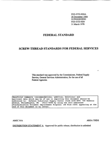
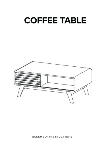
R310EN 2602 (2007.02)Compact ModulesBosch Rexroth AGCompact Module CKK withball rail system and ballscrew driveCompact Module CKR withball rail system and toothedbelt driveCKKDue to the connection plates, CKK and CKR have the same connection dimensions.CKR
Bosch Rexroth AGCompact ModulesR310EN 2602 (2007.02)Product overview of motors and controllersMotor selection based on drivecontrollers and control systemDigital AC servo motorSeveral motor-controller combinationsare available in order to provide themost cost-effective solution for everycustomer application.When dimensioning the drive unit,always consider the motor-controllercombination.Refer to the “Control systems, Electricalaccessories” catalogs for more information about motors and control systems.MSKMSMThree-phase stepping motorVRDM
R310EN 2602 (2007.02)Compact ModulesBosch Rexroth AG IndradriveA complete solutionEcodrive CsSD326SD328Compact Modules are available as complete solutions with motor, controller unit,and control system. Single and multi-axis positioning control system withpower pack
Bosch Rexroth AGCompact ModulesR310EN 2602 (2007.02)Overview of types with load capacitiesType designation (size)Compact Modules are identified by thetype designation and size.The type designations are also assignedto the design styles with the same external features but without drive unit.TypeC K K 20-145Compact Module (example) System Compact Module (C)Guideway Ball rail system (K)Drive unit Ball screw drive (K)GuidewaydimensionSizeor toothed belt drive (R) approx.(mm)Framedimension ATypeCompact ModulesGuidewayDrive unitCKKBall rail systemBall screw driveBall rail systemToothed belt driveCKRCompact Module
Bosch Rexroth AGCompact ModuleAACKKCKRDimensions A x H (mm) H1Compact ModulesHR310EN 2602 (2007.02)CKK 12-9090 x 40H1 Dynamic load capacity C (N)one carriage with CKKshort carriage with CKR564 620CKK 15-110110 x 506615 60025 340CKK 20-145145 x 658537 60061 080CKK 25-200200 x 10012755 00089 340CKR 12-9090 x 40564 6207 500CKR 15-110110 x 506614 56023 650CKR 20-145145 x 658534 80056 530CKR 25-200200 x 10012755 00089 340Note: All Compact Modules are also available without a drive unit.two carriages with CKKlong carriage with CKR7 500
10Bosch Rexroth AGCompact Modules CKKCompact ModulesR310EN 2602 (2007.02)Compact Modules with ball screw drive (CKK)Product overviewCompact Modules are precision, ready-to-install linear motion systems characterizedby their high performance and compact design.Favorable price/performance ratio and fast delivery times.Structural design– Extremely compact precisionaluminum profile (frame) with twointegrated ball rail systems– Precision ball screw drive accordingto tolerance grade 7 with backlashfree nut system– Fixed bearing end block made ofaluminum with two-row, preloadedangular-contact thrust ball bearing– Floating bearing end block withdouble ball bearings– One or two carriages made of aluminum with integrated runner blocksAttachments– Maintenance-free digital AC servodrives with integrated brake and attached feedback or stepping motors– Motor mount and coupling or timingbelt side drive for motor attachment– Switches– Socket with mating plug for theswitches– Mounting duct made of profiledaluminumOther distinguishing features– Economical maintenance thanks to one-point lubrication feature (greaselubrication) of ball rail systems and ball screw drive at both sides– Easy motor attachment by means of locating feature and fastening threads– Precise alignment and secure fastening of attachments through threads andpin holes and through one or two carriages– Internal components protected by rigid aluminum cover and two gap-typeseals made of PU strip reinforced with integrated steel cords– Adjustable switches over the entire travel range, switch activation withoutswitching cam– Two integrated zero-clearance ball rail systems provide optimized travelperformance, high load capacities, and high rigidity– Eceptionally low profile due to centrally located ball screw– High positioning accuracy and repeatability provided by ball screw drive withzero-backlash nut system– High travel speeds with simultaneous high precision over great lengths throughball rail systems, large screw diameters and screw leads, and double floatingbearingsDrive controllers and control systemsFor mounting and maintenance, see “Instructionsfor Compact Modules CKK”R310D4 2671Connection plate for easy installation
R310EN 2602 (2007.02)Compact ModulesScrew support for CKK 25-200Bosch Rexroth AGConnection elements for fasteningCompact Modules11
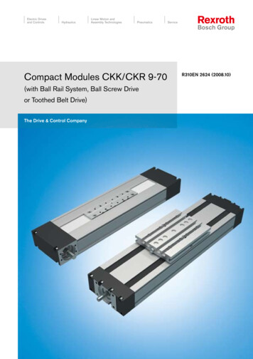
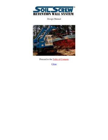
12Bosch Rexroth AGCompact ModulesR310EN 2602 (2007.02)Compact Modules CKKStructural designStructural design CKKBall screw drive with zero-backlash,cylindrical single nut2 Floating bearing end block3 Carriage with integrated runnerblocks3a Two carriages with two integratedrunner blocks each4 Aluminum cover5 Gap-type seal made of PU strip(recirculating)6 Fixed bearing end block7 Frame5134276891013aAttachments:8 Magnetic field sensor9 Mounting duct10 Socket/plug11 Connection plate3a1112 Motor13 Motor mount and coupling14 Timing belt side drive13121412
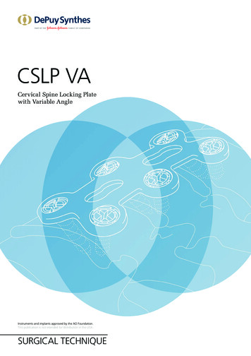
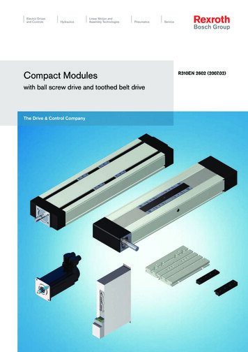
R310EN 2602 (2007.02)Compact ModulesBosch Rexroth AGStructural design of motormount and couplingA motor can be attached to all CompactModules with ball screw drive by meansof a motor mount and coupling.The motor mount serves to fasten themotor to the Compact Module and actsas a closed housing for the coupling.The motor’s drive torque is transmittedstress-free through the coupling to theCompact Module’s drive shaft.Our standard couplings compensate thesystem’s thermal expansion.If installing third-party couplings, thermalexpansion must be considered.1234MotorMotor mountCouplingCompact ModuleStructural design of timing beltside driveAll Compact Modules offer the option ofattaching the motor via a timing belt sidedrive.This makes the overall length shorterthan when attaching the motor with amotor mount and coupling.The compact, closed housing serves asprotection for the belt and as a motorbracket.Various gear ratios are also available:– i 1:1– i 1 : 1.5– i 1:2The timing belt side drive can beinstalled in four directions:– below, above (RV01 and RV02)– left, right (RV03 and RV04)12345678Compact ModuleDrawn, anodized profiled aluminumToothed beltAC servo motorPre-tensioning the toothed belt:Apply pretensioning force Fv tomotor (Fv is provided upon delivery)Fastening of belt pulleys with tensioning unitsCover plateCover 13
14Bosch Rexroth AGCompact ModulesR310EN 2602 (2007.02)Compact Modules CKKTechnical dataGeneral technical dataLoad capacities and momentsSizeNumber ofcarriagesBallscrewDynamic load capacity C (N)DynamicmomentsPlanar momentof inertiaMaximumlengthMovedmasszyyzGuideway Ball screw Fixed bearingCKK 12-90d0 x P12 x 212 x 512 x 1012 x 212 x 512 x 1016 x 516 x 1016 x 1616 x 516 x 1016 x 1620 x 520 x 2020 x 4025 x 1020 x 520 x 2020 x 4025 x 1032 x 532 x 1032 x 2032 x 3232 x 532 x 1032 x 2032 x 3212(lm 65 mm)CKK 15-11012(lm 85 mm)CKK 20-14512(lm 100 mm)CKK 25-20012(lm 175 mm)lm Center-to-center distance of 0612.003008.02200(with SPU5500)*3.182600058007810612.003008.02200(with SPU5500)*5.20* See section “Screw support for CKK 25-200” for lengths of 2,200 to 5,500Maximum permissible loadsSizeCKK 12-90CKK 15-110CKK 20-145CKK 25-200Number ofcarriages12121212Maximum permissible forces (N)Fz1max4 6207 50012 00019 49029 00047 11042 20068 550Acceptable loads(recommended from experience)Fz2max4 6207 5006 0009 74014 50023 55021 10034 270Fymax2 4904 0503 4805 6508 41013 66012 23019 880With respect to the desired service life,loads up to about 20% of the characteristic dynamic values (C, Mt, M L) haveproven to be acceptable.Maximum permissible moments (Nm)MtmaxM Lmax12516200240198313224146381001 0301 1801 3722092 2282 999At the same time, the following may notbe exceeded:– maximum permissible loads,– permissible drive torque,– permissible travel speed.
R310EN 2602 (2007.02)Compact ModulesModulus of elasticity EBosch Rexroth AGE 70,000 N/mm2WeightWeight calculation without motor andswitch.SizeBall screwCKK 12-90withWeight formula:Weight (kg/mm) · length L (mm) weight of all parts independent of length(carriage, end blocks, etc.) (kg)CKK 15-110withCKK 20-145withCKK 25-200withNumber of carriages Weight(kg)1 0.0055 · L 0.92 0.0055 · L 1.21 0.0092 · L 1.62 0.0092 · L 2.01 0.0178 · L 3.02 0.0178 · L 3.91 0.0299 · L 6.72 0.0299 · L 8.7M L/M LmaxMt/MtmaxM L/M LmaxCFz1maxCFz2maxCCompact Module with one carriageFymaxFymaxM L/M LmaxlmCompact Module with two carriageslm Center-to-center distance of carriagesNote on dynamic load capacities and momentsDetermination of the dynamic load capacities and moments is based on a travel life of 100,000 m.Often only 50,000 m are actually stipulated.For comparison: Multiply values C, Mt and M L from the table by 1.26.15
16Bosch Rexroth AGCompact ModulesR310EN 2602 (2007.02)Compact Modules CKKTechnical dataPermissible drive torque MpermCKK 12-90The values shown for Mperm are applicable under the following conditions:– Horizontal operation– Ball screw journal without keyway– No radial loads on ball screw journalConsider the coupling’s rated torque!12x2CKK 15-11020x20, 20x40, 25x10CKK 20-145CKK 25-200Ball screw journal with keywayFor reasons of stress concentration anda reduction of the effective diameter,observe the following maximum valuesfor drive torque!SizeCKK 12-90CKK 15-110CKK 20-145CKK 25-200Mperm(Nm)–5.011.518.0See section “Screw support for Compact Module CKK 25-200” for technical data oflengths 2,200 to 5,500.
R310EN 2602 (2007.02)Compact ModulesBosch Rexroth AGPermissible speed v17CKK 12-90Observe motor speed!12x2CKK 15-1101601501401301201101009080706050403020100v (m/min)CKK 6001800L (mm)CKK 25-200See section “Screw support for Compact Module CKK 25-200” for technicaldata of lengths 2,200 to 5,500.
18Bosch Rexroth AGCompact ModulesR310EN 2602 (2007.02)Compact Modules CKKTechnical dataSpecifications of timing belt side drive, floating bearing end for motor attachment via timing belt side driveMotorMSM 030C / MSK 030CFrictional torque M RRv (Nm) 0.35Permissible torque up to Reduced mass momentlength L1) atof inertia atGear ratio i i 1i 1.5 i 1i 1.5SizeBall screwLM RvM RvJRvJRvd0 x P(mm)(Nm)(Nm) (10–6 kgm2) (10–6 kgm2)12 x 27500.70.53814CKK 12-9012 x 57501.81.212 x 107502.51.716 x 514002.51.74116CKK 15-11016 x 1015002.51.716 x 1615002.51.720 x 5CKK 20-14520 x 2020 x 4025 x 1032 x 5CKK 25-20032 x 1032 x 2032 x 32MSM 040B / MSK 040C0.4Permissible torque up to Reduced mass momentlength L1) atof inertia ati 1i 1.5 i 1i 1.5LM RvM RvJRvJRv(mm)(Nm)(Nm) (10–6 kgm2) (10–6 7.54.04.64.65.05.05.05.0M Rv Permissible torque for system with timing belt side drive at motor journal (observe max. motor torque Mmax)M RRv Frictional torque of timing belt side drive at motor journalJRv Reduced mass moment of inertia of timing belt side drivei Timing belt side drive reduction1) Permissible torque for greater lengths available upon request2408225085
R310EN 2602 (2007.02)Compact ModulesBosch Rexroth AGMSK 050C0.45Permissible torque up toReduced mass momentlength L1) atof inertia ati 1i 2i 1i 2LM RvM RvJRvJRv(mm)(Nm)(Nm) (10–6 kgm2) (10–6 kgm2)120018001800180010.51616165.28.08.08.01310MSK 060C0.5Permissible torque up tolength L1) ati 1i 2LM RvM Rv(mm)(Nm)(Nm)Reduced mass momentof inertia ati 1i 2JRvJRv(10–6 kgm2) (10–6 013.0140026019
20Bosch Rexroth AGCompact ModulesR310EN 2602 (2007.02)Compact Modules CKKCalculationsFormulasNominal lifeNominal life in meters:L10 3( CF ) · 105mNominal life in hours:L10h L1060 · vFrictional torquefor motor attachment via motor mountand coupling:M R M RSfor motor attachment via timing belt sidedrive:Constants k1, k2, k3Frictional torque M RMR SizeCKK 12-90CKK 15-110CKK 20-145CKK 25-200M RSiBallscrewd0 x P12 x 212 x 512 x 1016 x 516 x 1016 x 1620 x 520 x 2020 x 4025 x 1032 x 532 x 1032 x 2032 x 32 M RRvL10 L10h C Fm v Nominal life in meters(m)Nominal life in hours(h)Dynamic load capacity(N)Mean equivalentdynamic load(N)Speed (from “Permissiblespeed” chart)(m/min)MR M RS Frictional torqueat motor journalFrictional torqueof systemM RRv i Frictional torque oftiming belt side driveat motor journalGear )(Nm)(Nm)k2k3Frictional torqueM 1.2
R310EN 2602 (2007.02)Compact ModulesMass moment of inertiaBosch Rexroth AGFor handling:6 · JM JfrJfr JM Mass moment of inertiaof external loadMass moment of inertiaof motor21(kgm2)(kgm2)For processing:1.5 · JM Jfrfor motor attachment via motor mountand couplingJfr JS J K JBrJS (k1 k2 · L k3· mfr) ·10-6Jtot Jfr JM JS J K JBr JMfor motor attachment via timing belt sidedriveJfr JSi2 JRv JBrJS (k1 k2 · L k3· mfr) ·10-6Jtot Jfr JM Rotary speedWhen attaching a gear motor, alsoinclude the gear mass moment of inertiaand gear reduction in the calculation.JS J J Ji 2 Rv M Bri · v · 1000Pn1 nmaxn1 Jtot Total mass momentof inertia(kgm2)Jfr Mass moment of inertiaof external load(kgm2)JS Mass moment of inertia ofsystem with external load (kgm2)J K Mass moment of inertiaof coupling(kgm2)JBr Mass moment of inertiaof motor brake(kgm2)JM Mass moment of inertiaof motor(kgm2)JRV Reduced mass moment ofinertia of timing belt sidedrive at motor journal(kgm2)mfr External load(kg)L Length of Compact Module (mm)i Gear ratiok1, k2, k3 Constants, see“Constants” tablev n1 nmax P i Permissible speedSpeedMaximum usablemotor speedScrew leadGear ratio(m/min)(1/min)(1/min)(mm)v Permissible speedfrom chartCoupling dataCouplings with data according to thetable are used with standard servomotors for Compact Modules CKK.SizeCKK 12-90CKK 15-110CKK 20-145CKK 25-200Rated torqueMass moment of inertia J KCoupling massof coupling MK(kg)(Nm)(10–6 kgm2)1412.130.0921412.130.0922642.300.140502000.7
22Bosch Rexroth AGCompact ModulesR310EN 2602 (2007.02)Compact Modules CKKCalculation exampleWhen dimensioning the drive unit, always consider the motor-controller combinationbecause the motor type and performance data (such as maximum usable speed andmaximum torque) are dependent on the controller or control system used.Starting dataA mass of 25 kg is to be moved 500 mmat a maximum travel speed of 40 m/min.Based on the technical data and connection dimensions, the following module is selected:500 mmm 25 kgCompact Module CKK 15-110– one carriage– 2% preload– with gap-type seal made of PU strip– with a size 41 AC servo motor attached via motor mount and couplingEstimation of Compact Modulelength LCalculation of Compact Modulelength LFrictional torque M Rm 25 kgLExcess travelMax. travel distanceCompact Module length LSelecting the ball screw driveSee section “Technical data” for charts.In general:It is preferable to choose the smallestpossible lead (resolution, braking distance, length).F 0N 2 · P 2 · 16 mm 32 mm strokeeff 2 · excess travel 500 mm 2 · 32 564 mm (stroke 2 · excess travel) 90 (according toformula given under “Components and ordering”for CKK 15-110) 564 90 654 mmPermissible ball screw drives according to “Permissible speed” chart forv 40 m/min and L 654 mm:Ball screw 16 x 10 and ball screw 16 x 16Selected ball screw drive (smaller lead):Ball screw 16 x 10with a maximum permissible drive torque of 9 Nmaccording to “Permissible drive torque” chartExcess travelMax. travel distanceCompact Module length LM RM R 2 · P 2 · 10 mm 20 mmstrokeeff 2 · excess travel500 mm 2 · 20 mm540 mm(stroke 2 · excess travel) 90 mm540 mm 90 mm630 mm M RS (see “Technical data”) 0.47 Nm
R310EN 2602 (2007.02)Mass moment of inertia JCompact ModulesBosch Rexroth AG23JS (k1 k2 · L k3 · mf r) · 10-6 kgm2 (6.076 0.029 · 630 mm 2.533 · 25 kg) ·10-6 kgm2 87.67 · 10-6 kgm2(k1. k2. k3 see “Constants” table)J K 12.13 · 10-6 kgm2JBr 16 ·10-6(see “Technical data”)kgm2Jfr JS J K JBr 115.8 · 10-6 kgm2For handling:JM Jfr6 115.8 · 10-66JM 19.3 · 10-6 kgm2Rotary speed nat v 40 m/minn1 i · v · 1000 1· 40 m/min · 1000 P10 mm 4000 min-1 nMmaxv 40 m/minResultCompact Module CKK 15-110Length:L 630 mmBall screw drive:Diameter:16 mmLead:10 mmNumber of carriages: 1Preload:2%Motor attachment via motor mount and couplingMotor with: – a maximum usable speed nmax 4,000 min-1– mass moment of inertia JM 19.3 · 10-6 kgm2– maximum permissible drive torque Mperm 9 NmConsider rated torque of coupling M K and frictional torque M R(M K 14 Nm; R R 0.47 Nm)These requirements are fulfilled by all AC servo motors approved for CKK 15-110in the table “Components and ordering”.The specific motor is selected:– according to criteria from the table “AC servo motor data”– by recalculating the drive unit with performance data from the“Control systems, Electrical accessories” catalog.
24Bosch Rexroth AGCompact ModulesR310EN 2602 (2007.02)Compact Modules CKKCKK 12-90 components and orderingPart number, lengthTypeGuidewayDrive unitCarriageR0360 300 00, . mm12 x 1012 x 5Ball screwsize d0 x P12 x 2ScrewjournalOne carriageTwo carriages lm 65Connection platewith- withoutConnection platewith- withoutwithout motor 1RV01 RV02RV03 RV0401Ø803010201400241with motor mountwith timing belt side drive 1) Attachment kit also available without motor (when ordering: enter “00” for motor)2) Including mounting accessoriesOrder example: see “Inquiry / Order form” section.Please make sure that the selected combination is a permissible one (load capacities, moments, max. speeds, motor data, etc.)!Switch mounting arrangementsA mounting duct is needed to fasten the switches. Switches may be mounted onlyon one side of the Compact Module (left or right).Refer to “Switch mounting arrangements” for more information on switch types andswitch mounting.
R310EN 2602 (2007.02)Compact ModulesBosch Rexroth AGMotor attachmentMotorCoverGearratioi Motor typeGap-typeseals madeof PU stripwith- withoutAttach- for motormentkit 1)without withbrakebrake00SwitchSocket, plugMounting 0001MSK 030C848505MSM 030C7273VRDM 3973738VRDM 3910394011MSK 030C848513MSM 030C7273Reed sensor58Hall sensorPNP - NCcontact59without switchwithout mounting duct00Magnetic field sensorReed sensor0610102Hall sensorPNP - NCcontact21 Mounting SocketPlugduct172522 Length LMagnetic field sensor with plug2)21MSK 030C848523MSM 030C72731.5Calculating the lengthof the Compact Module02FrictionaltorqueWith one carriage:L (stroke 2 · excess travel) 85 mmWith two carriages (lm 65 mm):L (stroke 2 · excess travel) 150 mmStroke Maximum distance fromcarriage center to the outermost switch activation points.0103Leaddeviation05PositioningaccuracyIn most cases, the recommended limitfor excess travel (braking distance) is:Excess travel 2 · screw lead PExample:Ball screw 12 x 10 (d0 x P),Excess travel 2 · 10 20 mm
Bosch Rexroth AG26Compact ModulesR310EN 2602 (2007.02)Compact Modules CKKCKK 12-90 dimensionsAll dimensions in mmDrawings not to scaleL/2Max. travel / 235Effective stroke / 235Excess travel21Ø8h7Excess travel Effective stroke / 2Max. travel / 22032La)Lube ports forcarriage attachmentslm 6554Ø 4H7 - 6 deep (4x)33,5Driving runner block27M4 - 7 deep (8x)a) One-point lubrication (grease lubrication):Each carriage can be lubed at either of the two funnel-typelube nipples DIN 3405-D3 (lubricating position at L/2)Module with one carriage: 1 lube port per side at L/2Refer to “Motors” for more information and dimensions. K Type RV01, RV02, RV03, RV04DLR E Type OF01Type MF01FHDGLMLFLM
R310EN 2602 (2007.02)Compact ModulesBosch Rexroth AG27M4 - 9 deep (4x)For connection plate,see section on “Mounting”For mounting duct,socket(Frame dimension)For fastening withclamping fixturesTypeRV01/RV02RV03/RV04MF01MotorMSM 030CMSK 030CMSM 030CMSK 030CVRDM 397VRDM 3910Dimensions (mm)DEi 1i ��138.5188110140LMwithbrake171.5213156.5186.5i 1LRi 1.5179165––––––––
28Bosch Rexroth AGCompact ModulesR310EN 2602 (2007.02)Compact Modules CKKCKK 15-110 components and orderingPart number, lengthTypeGuidewayDrive unitCarriageR0360 400 00, . mm0116 x 16OF0116 x 10without motor mountBall screwsize d0 x P16 x 5ScrewjournalØ11010203Ø11with keyway111213One carriageTwo carriages lm 85Connection platewith- withoutConnection platewith- without01400241with motor mountMF0101Ø1101020301400241RV01 RV02RV03 RV0401Ø1101020301400241with timing belt side drive 1) Attachment kit also available without motor (when ordering: enter “00” for motor)2) Including mounting accessoriesOrder example: see “Inquiry / Order form” section.Please make sure that the selected combination is a permissible one (load capacities, moments, max. speeds, motor data, etc.)!Switch mounting arrangementsA mounting duct is needed to fasten the switches. Switches may be mounted onlyon one side of the Compact Module (left or right).Refer to “Switch mounting arrangements” for more information on switch types andswitch mounting.
R310EN 2602 (2007.02)Compact ModulesBosch Rexroth AGMotor attachmentMotorCoverGearratioi Motor typeGap-typeseals madeof PU stripwithwithoutAttach- for motormentkit 1)without withbrakebrake00SwitchSocket, plugMounting que01MSK 030C848503MSK 040C8687VRDM 3973738VRDM 3910394005MSM 030C727306MSM 040B747511MSK 030C8485Hall sensorPNP - NCcontact13MSK 040C8687Magnetic field sensor with plug2)15MSM 030C7273Reed sensor58Hall sensorPNP - NCcontact59without switchwithout mounting duct17MSM 040B747521MSK 030C848523MSK 040C868725MSM 030C727327MSM 040B7475Calculating the lengthof the Compact Module00Magnetic field sensorReed sensor011.5Documentation00041290221 Mounting SocketPlugduct172522 Length LWith one carriage:L (stroke 2 · excess travel) 90 mmWith two carriages (lm 85 mm):L (stroke 2 · excess travel) 175 mmStroke Maximum distance fromcarriage center to the outermost switch activation points.0103Leaddeviation05PositioningaccuracyIn most cases, the recommended limitfor excess travel (braking distance) is:Excess travel 2 · screw lead PExample:Ball screw 16 x 10 (d0 x P),Excess travel 2 · 10 20 mm
Bosch Rexroth AG30Compact ModulesR310EN 2602 (2007.02)Compact Modules CKKCKK 15-110 dimensionsAll dimensions in mmDrawings not to scaleMax. travel / 2Excess travel Eff. stroke / 2Ø 5H7 - 8 deep (4x)Driving runner blockMax. travel / 239a)Eff. stroke / 239Excess travelLube ports forcarriage attachmentslm 85M5 - 10 deep (8x)a) One-point lubrication (grease lubrication):Each carriage can be lubed at either of the two funnel-typelube nipples DIN 3405-D3 (lubricating position at L/2)Module with one carriage: 1 lube port per side at L/2Refer to “Motors” for more information and dimensions.Type OF01Type RV01, RV02, RV03, RV04 KD LR E Type MF01FHDGLMLFLM
R310EN 2602 (2007.02)Compact Modules Bosch Rexroth AG31 M6 - 12 deep (4x)For connection plate,see section on “Mounting” For mounting duct,socket (Frame dimension) For fastening withclamping fixtures TypeRV01/RV02RV03/RV04MF01MotorMSM 030CMSM 040BMSK 030CMSK 040CMSM 030CMSM 040BMSK 030CMSK 040CVRDM 397VRDM 3910Dimensions (mm)DEi 1i ––171.5191.5213215.5156.5186.5i 1LRi �––––
32Bosch Rexroth AGCompact ModulesR310EN 2602 (2007.02)Compact Modules CKKCKK 20-145 components and orderingPart number, lengthTypeGuidewayDrive unitCarriageR0360 500 00, . mmwithout motor mountØ1420 x 4025 x 1020 x 20Ball screwsize d0 x P20 x 5Screw journalOne carriageTwo carriageslm 100 mmConnection platewithout withConnection platewithout with21 22 Ø14 with keyway 14 15 16OF0101Ø1424Ø14 with keyway17with motor mount21 22 23MF0101Ø1424with timing belt side drive 21 22 23 RV01RV02RV03RV04 01Ø1424 1) Attachment kit also available without motor (when ordering: enter “00” for motor)2) Including mounting accessoriesOrder example: see “Inquiry / Order form” section.Please make sure that the selected combination is a permissible one (load capacities, moments, max. speeds, motor data, etc.)!Switch mounting arrangementsA mounting duct is needed to fasten the switches. Switches may be mounted onlyon one side of the Compact Module (left or right).Refer to “Switch mounting arrangements” for more information on switch types andswitch mounting.
R310EN 2602 (2007.02)Compact ModulesBosch Rexroth AGMotor attachmentMotorCoverGearratioi Motor typeGap-typeseals madeof PU stripAttach- for motormentkit 1)withoutbrake00withbrakewithoutSwitchSocket, plugMounting with0002Frictionaltorque30MSK 040C868731VRDM 3913414232MSM 040B747533MSK 050C8889without switchwithout mounting duct00Magnetic field sensorReed sensor111MSK 040C868735MSK 050C888917MSM 040B747521MSK 040C868727MSM 040B747536MSK 050C88891.52Calculating the lengthof the Compact Module0102Hall sensorPNP - NCcontact21 Mounting SocketPlugduct172522 Length L0103LeaddeviationMagnetic field sensor with plug2)Reed sensor58Hall sensorPNP - NCcontact59With one carriage:L (stroke 2 · excess travel) 110 mmWith two carriages (lm 100 mm):L (stroke 2 · excess travel) 210 mmStroke Maximum distance fromcarriage center to the outermost switch activation points.05PositioningaccuracyIn most cases, the recommended limitfor excess travel (braking distance)
Bosch Rexroth AG 13 R310EN 2602 (2007.02) Compact Modules Structural design of motor mount and coupling A motor can be attached to all Compact Modules with ball screw drive by means of a motor mount and coupling. The motor mount serves to fasten the motor to the Compact Module and acts as a closed housing for the coupling.