Transcription
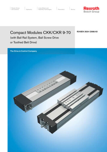
Compact Modules CKK/CKR 9-70(with Ball Rail System, Ball Screw Driveor Toothed Belt Drive)The Drive & Control CompanyR310EN 2624 (2008.10)
Bosch Rexroth AGLinear Motion and Assembly TechnologiesBall Rail SystemsRoller Rail SystemsLinear Bushings and ShaftsBall Screw DrivesLinear Motion SystemsBasic Mechanical ElementsManual Production SystemsTransfer Systemswww.boschrexroth.com/brl
R310EN 2624 (2008.10)Compact Modules CKK/CKR 9-70Compact ModulesOverview of types with load capacities4Product overview of motors and controllers6Compact Modules with ball screw drive (CKK)8Product Overview8Structural design10Technical data12CKK 9-7014Compact Modules with toothed belt drive (CKR)18Product Overview18Structural design20Technical data22CKR 9-7024Performance data28Switch mounting arrangements30Overview of switching systems30Magnetic field sensor with plug32Mounting34Mounting, clamping fixtures, centering ring34Connecting shafts for Compact Modules CKR35Connection plates for CKK/CKR 9-7036Connection of Compact Modules via vo motors40Three-phase stepping motors41Documentation42Inquiry / Order form43Bosch Rexroth AG
Bosch Rexroth AGCompact Modules CKK/CKR 9-70R310EN 2624 (2008.10)Overview of types with load capacitiesType designation (size)Typ eCompact Modules are identified by thetype designation and size.The type designations are also assignedto the design styles with the sameexternal features but without drive unit.C K K 9- 70Compact Module (example) System Compact Module (C)Guideway Ball rail system (K)Drive unit SizeBall screw drive (K) orToothed belt drive (R)Guidewaydimension ca. (mm)FramedimensionType AGuidewayDrive unitBall rail systemBall screw driveBall rail systemToothed belt driveCompact ModulesCKKCKRCompact Module
Bosch Rexroth AGH1Compact Modules CKK/CKR 9-70HR310EN 2624 (2008.10)AACKKCKRDynamic load capacity C (N)Compact ModuleDimensions A x H (mm)H1 (mm)Lmax (mm)Short carriageLong carriageCKK 9-7070 x 3244.565023603830CKR 9-7070 x 3244.5150023603830Note: All Compact Modules are also available without a drive unit.
Bosch Rexroth AGCompact Modules CKK/CKR 9-70Product overview of motors and controllersMotor selection based on drivecontrollers and control systemDigital AC servo motor MSKSeveral motor-controller combinationsare available in order to provide themost cost-effective solution for everycustomer application.When dimensioning the drive unit,always consider the motor-controllercombination.For more detailed information on motorsand control systems, please refer tothe catalogs “ECODRIVE Cs” and“IndraDrive for Linear Motion Systems.”Digital AC servo motor MSMThree-phase stepping motor VRDMR310EN 2624 (2008.10)
R310EN 2624 (2008.10)Compact Modules CKK/CKR 9-70Bosch Rexroth AG Digital controllersIndraDriveA complete solutionDigital controllersECODRIVE CsPower electronicsSD326SD328Compact Modules are available as complete solutions with motor, controller unit,and control system.Twin LineProfi StepHandAutocontrol unitRS232
Bosch Rexroth AGCompact Modules CKK/CKR 9-70R310EN 2624 (2008.10)Compact Modules CKKProduct OverviewCompact Modules are precision, ready-to-install linear motion systems characterizedby their high performance and compact design.Favorable price/performance ratio and fast delivery times.Structural design– Extremely compact precisionaluminum profile (frame) with twointegrated ball rail systems– Precision ball screw drive accordingto tolerance grade 7 with backlashfree nut system– Fixed bearing end block made ofaluminum with two-row, preloadedangular-contact thrust ball bearing– Floating bearing end block withdouble ball bearings– Short or long carriage made ofaluminum with integrated runnerblocksAttachments– Maintenance-free digital AC servodrives with integrated brake andattached feedback or steppingmotors– Motor mount and coupling or timingbelt side drive for motor attachment– Switches– Socket with mating plug for theswitches– Mounting duct made of profiledaluminumFor mounting and maintenance,see “Instructions for CompactModules CKK” R310D4 2671Other distinguishing features– Economical maintenance thanks to one-point lubrication feature (greaselubrication) of ball rail systems and ball screw drive at both sides– Easy motor attachment by means of locating feature and fastening threads– Precise alignment and secure fastening of attachments through threads andpin holes and through short or long carriage– Internal components protected by rigid aluminum cover and two gap-typeseals made of PU strip reinforced with integrated steel cords– Adjustable switches over the entire travel range, switch activation withoutswitching cam– Two integrated zero-clearance ball rail systems provide optimized travelperformance, high load capacities, and high rigidity– Exceptionally low profile due to centrally located ball screw– High positioning accuracy and repeatability provided by ball screw drive withzero-backlash nut system– High travel speeds with simultaneous high precision over great lengths throughball rail systems, large screw diameters and screw leads, and double floatingbearingsDrive controllers and control systems
R310EN 2624 (2008.10)Compact Modules CKK/CKR 9-70Bosch Rexroth AGConnection plate for easy installation
10Bosch Rexroth AGCompact Modules CKK/CKR 9-70R310EN 2624 (2008.10)Compact Modules CKKStructural designStructural design CKKBall screw drive with zero-backlash,cylindrical single nut2 Floating bearing end block3 Short carriage with two integratedrunner blocks3a Long carriage with four integratedrunner blocks4 Aluminum cover5 Gap-type seal made of PU strip(recirculating)6 Fixed bearing end block7 Frame5134276891013aAttachments:8 Magnetic field sensor9 Mounting duct10 Socket/plug11 Connection plate3a1112 Motor13 Motor mount and coupling14 Timing belt side drive13121412
R310EN 2624 (2008.10)Compact Modules CKK/CKR 9-70Bosch Rexroth AGStructural design of motormount and couplingA motor can be attached to all CompactModules with ball screw drive by meansof a motor mount and coupling.The motor mount serves to fasten themotor to the Compact Module and actsas a closed housing for the coupling.The motor’s drive torque is transmittedstress-free through the coupling to theCompact Module’s drive shaft.Our standard couplings compensate thesystem’s thermal expansion.If installing third-party couplings, thermalexpansion must be considered.1234MotorMotor mountCouplingCompact ModuleStructural design of timing beltside driveAll Compact Modules offer the option ofattaching the motor via a timing belt sidedrive.This makes the overall length shorterthan when attaching the motor with amotor mount and coupling.The compact, closed housing serves asprotection for the belt and as a motorbracket.Various gear ratios are also available:– i 1:1– i 1 : 1.5The timing belt side drive can beinstalled in four directions:– below, above (RV01 and RV02)– left, right (RV03 and RV04)12345678Compact ModuleDrawn, anodized aluminum profileToothed beltAC servo motorPre-tensioning the toothed belt:Apply pretensioning force Fpr tomotor (Fpr is provided upon delivery)Fastening of belt pulleys with tensioning unitsCover plateCoverFpr11
12Bosch Rexroth AGCompact Modules CKK/CKR 9-70R310EN 2624 (2008.10)Compact Modules CKKTechnical dataGeneral technical dataSizeCarriage BallscrewDynamic load capacity C (N)DynamicmomentsPlanar momentof inertiaMaximumlengthMoved mass ofsystem mca (kg)zyyzGuideBallFixedscrewbearingd0 x P way8 x 2.52360220016003830CKK 9-70shortlongSizeCarriage Maximum permissible forces (N)Fz1 maxFz2 maxshort11801180long23602360CKK 9-70Fy .3Connection plateLmax withoutwith(mm)6500.150.250.260.42Maximum permissible moments (Nm)Weight with ball screw (kg)Mx maxMy max, Mz max237 3.16 ·10-3 · L 0.394734 3.16 ·10-3 · L 0.49Acceptable loads(recommended from experience)With respect to the desired service life,loads up to about 20% of the characteristic dynamic values (C, Mt, M L) haveproven to be acceptable.Modulus of elasticity EE 70,000 N/mm2WeightWeight calculation without motor andswitches.Weight formula:Weight factor (kg/mm) · length L (mm) weight of all parts of fixed length (carriage,end blocks, etc.) (kg)Note on dynamic load capacities andmomentsDetermination of the dynamic loadcapacities and moments is based on atravel life of 100,000 m.Often only 50,000 m are actuallystipulated.For comparison: Multiply values C, Mtand M L from the table by 1.26.At the same time, the following may notbe exceeded:– maximum permissible loads,– permissible drive torque,– permissible travel speed.Mt/Mx maxFz1 maxFz2 maxFy maxM L/My maxFy maxM L/Mz maxShort carriageM L/Mz maxLong carriage
R310EN 2624 (2008.10)Compact Modules CKK/CKR 9-70Maximum permissible drivetorque for mechanical systemMmechBosch Rexroth AG13Mmech (Nm)0,8The values shown for Mmech are applicable under the following conditions:– Horizontal operation– Ball screw journal without keyway– No radial loads on ball screw journal0,7Consider the coupling’s rated torque!0,10,00,60,50,40,30,2100Maximum permissiblelinear speed of mechanicalsystem vmech200300400500600700L (mm)vmech (m/s)0,300,25Consider motor speed!0,200,150,100100200300400500600700L (mm)Specifications of timing belt side drive, floating bearing end for motor attachment via timing belt side driveMotorFrictional torque M Rsd (Nm)Gear ratio i SizeCKK 9-70Ball screwd0 x P8 x 2.5MSM 030B/MSK 030C0.15Permissible torque up to length L1) ati 1i 1.5LMsd(mm)(Nm)4500.7Reduced mass moment of inertia ati 1i 1.5MsdJsd(Nm)(10–6 kgm2)0.4545.6Jsd(10–6 kgm2)17.7Msd maximum permissible drive torque of the timing belt side drive (consider the maximum torque of the motor Mmax)M Rsd frictional torque of timing belt side drive at motor journalJsd Mass moment of inertia of timing belt side drivei timing belt side drive reduction1) Permissible torque for greater lengths available upon requestConstants kj fix, kj var, kj mFrictional torque M RsdSizeCKK 9-70Coupling dataSizeBallscrewd0 x P8 x 2.5Constantskj fixshortlongcarriage carriage0.8710.891Motorattachmentkj var0.004 0.158CKK 9-70MSM 020BMSM 030BMSK 030CVRDM 368short carriage/long carriage0.07Coupling dataRated torqueFor calculation and calculation example,see catalog Compact ModulesR310EN 2602Frictional torque M Rskj m (Nm)McN(Nm)1.93.73.75.5Mass momentof inertiaJc(10–6 kgm2)2.17.07.020.0Weightmc(kg)0.0390.0750.0750.040
14Bosch Rexroth AGCompact Modules CKK/CKR 9-70R310EN 2624 (2008.10)Compact Modules CKKCKK 9-70 Components and OrderingPart number, lengthTypeGuidewayDrive unitCarriageR0360 200 00, . mmScrewjournalBall screwsize d0 x P8 x 2.5Short carriage (32 mm) Long carriage (73 mm)Connection plateConnection platewithout withwithout withWithout motor 401Ø60101400241With motor mountWith timing belt side drive 1) Attachment kit also available without motor (when ordering: enter “00” for motor)2) Including mounting accessoriesOrder example: see “Inquiry / Order form” section.Please make sure that the selected combination is a permissible one (load capacities, moments, max. speeds, motor data, etc.)!Switch mounting arrangementsA mounting duct is needed to fasten the switches. Switches may be mounted onlyon one side of the Compact Module (left or right).Refer to “Switch mounting arrangements” for more information on switch types andswitch mounting.
R310EN 2624 (2008.10)Compact Modules CKK/CKR 9-70Motor attachmentMotorCoverGearratioi Motor typewithout withbrakebrakeGap-type sealsmade of PU stripwithout withAttach- for motormentkit1)Bosch Rexroth AGSwitchSocket, plugMounting duct15DocumentationStandard Measurementreportreport0001MSK030C848502VRDM M030B707121MSK030C848523MSM030B70Without switchWithout mounting duct0002FrictionaltorqueMagnetic field sensorReed sensor0102Hall sensorPNP - NCcontact21Mountingduct2522 Length LSocketPlug1711.5Calculating the lengthof the Compact Module (example)71Magnetic field sensor withReed sensor58Hall sensorPNP - NCcontact59L (stroke 2 · excess travel) L ca 30 mmStroke Maximum distance fromcarriage center to theoutermost switch activationpoints.Stroke 200 mmL ca 73 mmL ((200 2 · 2.5) 73 30) mmL 308 mmplug2)0103Leaddeviation05PositioningaccuracyIn most cases, the recommended limitfor excess travel (braking distance) is:Excess travel 2 · screw lead PExample:Ball screw 8 x 2.5 (d0 x P),Excess travel 2 · 2.5 5 mm
Bosch Rexroth AG16Compact Modules CKK/CKR 9-70R310EN 2624 (2008.10)Compact Modules CKKCKK 9-70 DimensionsAll dimensions in mmDrawings not to caleMax. travel / 2Effective stroke / 2Max. travel / 2Lca 32 (short carriage)Effective stroke / 2Excesstravel16Ø6h7ExcesstravelLca 73 (long carriage)1822L/2One-point lubrication on both sides(grease lubrication): Funnel-typelube nipple DIN 3405-D3LLong carriage40Ø3H7 - 5 deep (8x)40M3 - 5 deep (8x)Lube ports for grease lubrication;ports closed with set screw M3.25152573RV01-RV04 K DLsd E OF01MF01FHDGLmLfLm29
R310EN 2624 (2008.10)Compact Modules CKK/CKR 9-70Bosch Rexroth AG172333Ø282,5 deepFor connection plate,see section on “Mounting”M4 - 8 deep (4x)407044,53231,3BShort carriage5Ø3H7 - 5 deep (2x)A45 3,2B3,2 1,81,34,54,82,5A40(Frame dimension)25M3 - 5 deep (4x)322,8For mounting duct, socketFor fastening with clamping fixturesTypeRV01/RV02RV03/RV04MF01MotorMSM 030BMSK 030CMSM 020BMSM 030BMSK 030CVRDM 368Lube ports for greaselubrication;ports closed with setscrew M3.Dimensions (mm)Di 1605442605457.2Ei ke144213140144157213Lsd157154––––
18Bosch Rexroth AGCompact Modules CKK/CKR 9-70R310EN 2624 (2008.10)Compact Modules CKRProduct OverviewCompact Modules are precision, ready-to-install linear motion systems offering highperformance, compact design, and good price/performance ratio with fast deliverytime.Structural design– Extremely compact precision aluminum profile with two integrated ballrail systems for optimal travel performance and movement of heavy loadsat high travel speeds– Ready-to-install Compact Modulesin selectable lengths up to Lmax– Short or long carriage made ofaluminum with integrated runnerblocks– Driven by a pre-tensioned toothedbeltAttachments– Maintenance-free digital servo driveswith integrated brake and attachedfeedback– Gear reducer– Reed or Hall sensors– Socket with mating plug for theswitches– Aluminum profile mounting ductOther distinguishing features– Precise alignment and secure fastening of attachments with threads andpin holes and through short or long carriage– Idler (non-drive) end enclosure with integrated belt-tensioning system.Pulley ball bearings are lubricated for life– Economical maintenance thanks to one-point lubrication feature (greaselubrication) for ball rail systems at sides or through the carriage– Easy motor attachment by means of locating feature and fastening threadson drive end enclosure– Two integrated zero-clearance ball rail systems provide optimized travelperformance, high load capacities, and high rigidity– High travel speed with high precision and smooth operation over long lengths– Gap-type sealings and side-mounted aluminum rails for guiding the toothed belt– Adjustable switches over the entire travel range, switch activation withoutswitching cam
R310EN 2624 (2008.10)Compact Modules CKK/CKR 9-70Connection plate for easy installationBosch Rexroth AGGear reducer:A variety of gear ratios allow an optimal match between theload and the drive motor inertia.19
20Bosch Rexroth AGCompact Modules CKK/CKR 9-70R310EN 2624 (2008.10)Compact Modules CKRStructural designStructural design CKR5123Toothed beltDrive end enclosureCarriage versions– Short carriage with two runnerblocks– Long carriage with four runnerblocks4 Frame5 Idler (non-drive) end enclosure431Attachments:6 Magnetic field sensor7 Mounting duct8 Socket/plug9 Motor10 Gear reducer11 Connection plate782611910
R310EN 2624 (2008.10)Compact Modules CKK/CKR 9-70Bosch Rexroth AGStructural design of gearreducerFor all Compact Modules CKR, aplanetary gearbox can be installed via aflange. The flange serves as a mountingpoint for the gearbox to the CompactModule. This direct connection eliminates the need for a coupling, therebyminimizing torsional deflection.Several different gear ratios are available:i 5i 1012345MotorGear reducerFlangeDrive end enclosureCompact Module4352121
22Bosch Rexroth AGCompact Modules CKK/CKR 9-70R310EN 2624 (2008.10)Compact-Module CKRTechnical dataGeneral technical dataSizeCarriageBelt typeDynamicDynamicload capacity momentsof guidewayPlanar moment ofinertiaMoved mass mB (kg) MaximumlengthConnection platezyySpecificspring ratezCKR 9-70C(N)23603830short AT 3long AT 3Mt(Nm)4776ML(Nm)794Iy(cm4)8.5Iz(cm4)55.1without with0.120.280.230.45Lmax(mm)1500cspec(N/mm · m)275Toothed belt stretch L (F · L)/cspecMaximum permissible loadsSizeCarriageCKR 9-70Maximum permissible forces (N)Fz1 maxFz2 maxshort11801180long23602360Modulus of elasticity ESizeCKR 9-70CarriageNote on dynamic load capacities andmomentsDetermination of the dynamic loadcapacities and moments is based on atravel life of 100,000 m.Often only 50,000 m are actuallystipulated.For comparison: Multiply values C, Mtand M L from the table by 1.26.Maximum permissible moments (Nm)Mx maxMy max, Mz max2374728E 70,000 N/mm2Drive type(mm)short Without driveDrive i 1long Without driveDrive i 1WeightWeight calculation without motor, switches and sensors.Fy max15901180Weight(kg)0.0028 ·0.0028 ·0.0028 ·0.0028 ·L 0.585L 0.575L 0.74L 0.73Additional weight of gear reducer(kg)–0.435–0.435Weight formula:Weight factor (kg/mm) · length L (mm) weight of all parts of fixed length (carriage,drive and idler end enclosures, etc.) (kg) additional mass (kg)Mt /Mx maxFz1 maxM L/My maxFz2 maxFy maxFy maxM L/Mz maxM L/Mz maxLong carriageShort carriage
R310EN 2624 (2008.10)Compact Modules CKK/CKR 9-7023Bosch Rexroth AGDrive dataSizeCKR 9-70Drive typei 1Gear reducerGear reducerratioiMax. peu(mm/rev)72.0 AT 314.47.2WidthToothpitchb(mm)25Max. belt driveBelt elasticitytransmission force limitTFFperm(mm)(N)(N)326011001) Maximum 1,000 cycles/hourDrive data without motor (i 1)SizeDrive unit diameter(mm)CKR 9-70Frictional torque dataLead constantTravel speedu(mm/rev)22.92Belt typevmech(m/s)72.0 up to 3AT 3Width 25 mmSizeMotorGear unit typeCKR 9-70MSM020BMSK030CGear reducerFor calculation and calculation example, see catalog Compact Modules R310EN 2602Reduced mass moment of inertia atmotor journalshort carriage(kgm2)3.01 · 10-5i5, 10long carriage(kgm2)3.9 · 10-5M RS(Nm)0.25M RLP(Nm)0.03
24Bosch Rexroth AGCompact Modules CKK/CKR 9-70R310EN 2624 (2008.10)Compact Modules CKRCKR 9-70 Components and OrderingPart number, lengthTypeGuidewayDrive unitCarriageShaftformotorShort (80 mm)Connection platewithoutwithR0364 200 00, . mmWithout Gearkeyway reduceri 1i 5, 10Long (108 mm)Connection platewithoutwithWithout left07With driveMA02010140024101400241With gear reducer MG 10MG11MG1001MG10withgearreducer,right08With gear reducer MG 11MG11MG11MG1001withgearreducer,left091) Attachment kit also available without motor (when ordering: enter “00” for motor)2) Including mounting accessoriesNote: For gear unit performance data, see “Performance data” section.CKR with second shaft endIn types MA05, MA06, MG10 and MG11 a second drive shaft end can be madeavailable by removing the screws and cover.
R310EN 2624 (2008.10)Motor attachment1)Directdrive00i 500Compact Modules CKK/CKR 9-70Motori 10Bosch Rexroth AGSwitchSocket, plugMounting portWithout switchWithout mounting duct0000Hall sensorPNP - NCcontact21 Mounting SocketPlugduct1725Length L22Magnetic field sensor with plug2)11211222MSK 030CMSM 020BLength of the Compact ModuleL (stroke 2 · excess travel) L T 10 mmStroke Maximum distance fromcarriage center to the outer most switch activation points.Stroke 400 mmL T 108 mmL ((400 2 · 110) 108 10) mmL 738 mm846885Reed sensor58Hall sensorPNP - NCcontact59Measurement report02FrictionaltorqueMagnetic field sensorReed sensor250105Positioningaccuracy69The excess travel must be greater thanthe braking distance.You can use acceleration travel s as arecommended value for the braking distance (see “Performance data” tables).Example CKR 9-70:Horizontal operation with motor MSK030C, i 5, m 2 kg, s 105 mmExcess travel 105 mm (110 mmassumed)A mounting duct is needed to fasten theswitches. Switches may be mountedonly on one side of the Compact Module(left or right).Refer to “Switch mounting arrangements” for more information on switchtypes and switch mounting.
Bosch Rexroth AG26Compact Modules CKK/CKR 9-70R310EN 2624 (2008.10)Compact Modules CKRCKR 9-70 DimensionsAll dimensions in mmDrawings not to caleMax. travel / 2Max. travel / 2Effective stroke / 2Effective stroke / 2Excesstravel36ExcesstravelLca 108 (long carriage)Lca 80 (short carriage)421216,329M3 - 6 deep (8x)18One-point lubrication on both sides(grease lubrication): Funnel-typelube nipple DIN 3405-D3L/2Ø26,5H7L3 deepLong carriage12,5 12,5 1512,5 12,5M3 - 6 deep (8x)- 6 deep (4x)14,513,5Ø3H7Ø8h7OA01Lube ports for grease lubrication;ports closed with set screw M4.108MA01 / MA02MA05 / MA0636X31,336122X15Ø8 h742702Ø 26,5 H714,57070Ø26,5 H7Ø 8h714,5Ø10 H712 deep
R310EN 2624 (2008.10)Compact Modules CKK/CKR 9-70Bosch Rexroth AG27For connection plate,see section on “Mounting”2144,53231,3B70A(Frame dimension)M3 - 6 deep (4x)4,84,512,5 12,53,21,313,5B3,2 1,845 2,5AShort carriage2,8For mounting duct, socketLube ports for grease lubrication;ports closed with set screw M4.MG10 / MG11MotorXMSM 020BLfMSK 030CLmFor fastening withclamping fixturesDM3 - 6 deep (2x)Dimensions (mm)DLfwithoutbrake42 91.010954 91.0188Lmwithbrake140.0213.0
28Bosch Rexroth AGCompact Modules CKK/CKR 9-70R310EN 2624 (2008.10)Compact ModulesPerformance datafor motors with brake in horizontal operationcThe data below apply only to the combination described here.For other combinations the performance data must be recalculated.CKR 9-70:– with long carriage– without connection plate– with gear reducerServomotor MSK 030C and IndraDrive controller1)Connection voltage: 3 x 400 VGear reducer ratioMassAcceleration time tAcceleration distance sAcceleration aSpeed vRepeatabilityi 615214612.61.920.1i 51183.9102561233.733679.93.53779.6Servomotor MSM 020B and Regler ECODRIVE Cs controller1)Connection voltage: 1 x 230 VGear reducer ratioMassAcceleration time tAcceleration distance sAcceleration aSpeed 111464.1i 51.513554.30.720.11) For additional information, refer to the “ECODRIVE Cs” and “IndraDrive for Linear Motion Systems” catalogs.i 102.535610.20.360.1
R310EN 2624 (2008.10)Compact Modules CKK/CKR 9-70Bosch Rexroth AG29
30Bosch Rexroth AGCompact Modules CKK/CKR 9-70R310EN 2624 (2008.10)Switch mounting arrangementsOverview of switching systemsMagnetic field sensorMagnetic field sensor with plugThe following switch categories can be used with the Compact Module:– Magnetic field sensor (Hall and Reed sensors)The entire switching system must be mounted on one side of the Compact Module!Magnetic field sensorHall and Reed sensor1 Socket and plug2 Switch3 Mounting duct(aluminum alloy, black anodized)2cThe magnetic field sensors aresuitable for travel speeds up to 2 m/s.Short stroke: Take the length of theswitch and socket into consideration!35Set screw forfixing in place361356,5Active surfaceMagnetic field sensors with potted cable.Version:– Hall sensor (normally closed) or– Reed sensor (change-over)Mounting instructions:Switches may be mounted only on one side of the Compact Module (left or right) and only after installing the Compact Module tothe mounting base. A mounting duct is needed to fasten the switches.Hall sensorContact typeOperating voltagePower consumptionOutput currentCable lengthHousing protection classShort-circuit protectionMaximum travel speedPin assignmentPNP - NC / NO3.8–30 V DCmax. 10 mAmax. 20 mA2 m (10 m upon request)IP 66No2 m/sHall sensorReed sensorContact typeSwitching voltageSwitching currentCable lengthHousing protection classMaximum travel speedChange-overmax. 100 V DCmax. 0.5 mA2 m (10 m upon request)IP 662 m/sImportant: 2 switching points!White: 3.8.30 VDCGreen: OutputBrown:0 V groundReed sensorBrownWhiteGreen
R310EN 2624 (2008.10)Compact Modules CKK/CKR 9-70Bosch Rexroth AGMounting ductFunction:– To attach and secure magnetic fieldsensors– Cable routing123,51419Mounting instructions:The mounting duct is hooked into theT-slots of the module frame and securedwith set screws.Set screws are included.The switches are slid into the T-slot ofthe mounting duct and secured withset screws.The socket and plug have 16 pins.Socket and plug are not wired.This allows optimal assignment of switchpositions during start-up.One plug is included.The plug can be installed in three directions.4,54927,5Ø2660Part numbers of the magnetic fieldsensors and accessories5028,53Item12316-pin plugPart numbersSocket-plugMagnetic field sensor– Reed sensor– Hall sensor (PNP - NC)Mounting ductR0375 400 00R3476 009 03R3476 010 03R0399 800 63PG 16Socket and plugAttach the socket on the side with themagnetic field sensor.31
32Bosch Rexroth AGCompact Modules CKK/CKR 9-70R310EN 2624 (2008.10)Switch mounting arrangementsMagnetic field sensor with plugWith magnetic field sensors, switch activation is direct (without switching cam).The switch positions can be adjustedfreely over the entire travel range.Sensors may be mounted only on oneside of the Compact Module (left orright) and only after installing theCompact Module to the mounting base.Switch positions:1 Limitation at end of stroke (recommendation: Reed or Hall sensor)2 Reference point in middle of stroke(recommendation: Hall sensor)Sensor mounting assemblyconsists of:3 Sensor (Hall or Reed)4 Sensor mount incl. set screws (loose)and square nut 4a Cable holder (3 units) incl. set screw(loose)4a412153VersionSensor mounting assembly with Reed sensorSensor mounting assembly with Hall sensorPart numberR0375 300 07R0375 300 08Set screw M3Sensor configuration:Activation point26,4Sensor mountA sensor mount (1) is required to attachthe sensors. It is hooked into theupper slot on the Compact Module andsecured with set screws (2).The sensors are pushed into the upperslot of the sensor mount and fixed with aset screw.The square nut with set screw (3) servesas a positive stop for the sensor (switchposition when changing sensors).Parts are included with the sensor mounting assembly.7,9
R310EN 2624 (2008.10)Compact Modules CKK/CKR 9-70Technical data and orderingPart numberDimension XContact typeOperating voltagePower consumptionOutput currentHousing protection classShort-circuit protectionPermissible travel speedHousing materialPin assignmentBosch Rexroth AGHall sensorR3476 024 0313.65 mmPNP - NC3.8 to 30 V DCmax. 10 mAmax. 20 mAIP 66No2 m/sUltramidReed sensorPart numberR3476 023 03Dimension X9 mmContact typeChange-overSwitching voltagemax. 100 V DCSwitching currentmax. 500 mAHousing protection class IP 66Permissible travel speed 2 m/sHousing materialUltramidImportant: 2 switching points1: 3.8 to30 VDCHall sensorReed sensor14: Output433: 0 V ground– Hall sensor (PNP - NC contact)The extension cable (approx. 5 m) issupplied complete with a femaleconnector M8x1 for connection to thesensor.– Reed sensor (change-over)43M8x1Extension cable for sensor(Reed/Hall)331Extension cablePart numberConnector contact 13R3476 025 03to corebrown blue 354blackProtection classIP 66 when connected
34Bosch Rexroth AGCompact Modules CKK/CKR 9-70R310EN 2624 (2008.10)MountingMounting, clamping fixtures, centering ringMounting with clamping fixturesCompact Modules are mounted usingclamping fixtures.cDo not secure or support theCompact Module at the end enclosures!The frame is the load-bearing part!When mounting Compact Modules,please note the maximum tighteningtorques listed in the table.82DCClamping fixturesDGGDimensions he centering ring serves as a positioningaid and for positive locking whenmounting customer attachments to thecarriage.It creates a positive-locking connectionwith good reproducibility.Material: steel (stainless)Countersink for threadM 5 (ISO 4762)ECPart numberClamping fixturesR1419 010 01Tightening torques of fasteningscrews– with friction factor 0.125– strength class 8.8Centering ringFRecommended number of clampingfixtures:– 3 pieces per 500 mm and sideFrame size 70 mmEF95cEØ Sizea) Customer attachmentb) Centering ringc) Carriage(mm)57912167-59-59-712 - 916 - 12Dimensions (mm)ABCk6k6 0.15–3.47–5.59–6.612–9.016– 11.0753.4953.4975.51296.616129.0Part numberD–0.23.03.04.04.06.03.03.53.54.05.0E 01.61.61.62.02.0H1 0.21.61.62.12.13.11.62.12.12.13.1H2 0.2–––––1.61.61.62.12.1R0396 605 42R0396 605 43R0396 605 44R0396 605 45R0396 605 46R0396 605 47R0396 605 48R0396 605 49R0396 605 50R0396 605 51
R310EN 2624 (2008.10)Compact Modules CKK/CKR 9-70Bosch Rexroth AG35Connecting shafts for Compact Modules CKRConnecting shafts––––Compensate for misalignmentsAre backlash-free and torsionally stiffBridge large distances between axesCan be mounted radially using splitclamping hubs (installation andremoval without shifting pre-alignedaxes)– Dynamically ba
Bosch Rexroth AG 11 F pr R310EN 2624 (2008.10) Compact Modules CKK/CKR 9-70 Structural design of motor mount and coupling A motor can be attached to all Compact Modules with ball screw drive by means of a motor mount and coupling. The motor mount serves to fasten the motor to the Compact Module and acts as a closed housing for the coupling.