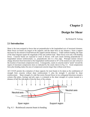
Transcription
152INTERNATIONAL JOURNAL OF SCIENTIFIC & ENGINEERING RESEARCH, VOLUME 9, ISSUE 7, JULY-2018ISSN 2229-5518Optimum location of a shear wall in a R.C buildingMr.Madhu sudhan rao.kondapalliDepartment of civil engineering, anil neerukonda institute of technology and sciencesSanghivalasa,visakhapatnam,andhra pradesh,531162,india.Mail id : madhusudhan.14.civil@anits.edu.inAbstract: Shear walls are commonly used as vertical structural element for resisting the lateral loads that may be induced by theloads due to wind and earthquake. Besides that, they also carry gravity loads. A well designed system of shear wall in buildingframe improves seismic performance significantly. This study aims at comparing various parameters such as storey drift, storeyshear and storey displacement of a building under lateral loads based on strategic positioning of shear walls. Linear staticanalysis has been adopted in this paper. The software used is E-TABS.Keywords: story displacement, storey drift, linear analysis, shear wall, seismic zone.1. IntroductionShear wall systems are one of the most commonly usedlateral load resisting systems in high rise buildings. Anintroduction of shear wall represents a structurally efficientsolution to stiffen a building, because the main function of ashear wall is to increase the rigidity for lateral loadresistance. In modern tall buildings, shear walls arecommonly used as a vertical structural element for resistingthe lateral loads that may be induced by the effect of windand earthquakes. Shear wall has high in-plane stiffness andstrength which can be used to simultaneously resist largehorizontal loads and support gravity loads, whichsignificantly reduce lateral sway of the building and therebyreduce damage to structure. Shear walls in buildings must besymmetrically located in plan to reduce ill-effects and twistin buildings.Shear walls are like vertically-oriented wide beams whichtransfer these horizontal forces to the next element in theload path. These other components in the load path may beother shear walls, floors, foundation walls, slabs or footingsand finally these walls carry earthquake loads downwards tothe foundation. These walls generally start at foundationlevel and are continuous throughout the building height. It ispossible for a Reinforced concrete multi-storey building toresist both the vertical and horizontal load withoutconsidering a shear wall, but the problem is beam andcolumn sizes are become quite heavy, steel quantityrequirement is also in large amount thus there is lot ofcongestion takes place at joints and it is difficult to place andvibrate concrete.When shear walls are situated in advantageous positions inthe building, they can form an efficient lateral force resistingsystem by reducing lateral displacements under earthquakeloads. Therefore it is very necessary to determine effective,efficient and ideal location of shear wall.It may be possible to decide the optimum or ideal location ofshear wall in a building by comparing various parameterssuch as storey displacement, storey (or) base shear, storeydrift and reinforcement requirement in columns etc of abuilding under lateral loads based on strategic positioning ofshear wall. In our project some of the above parameters arebeing calculated by using software E-TABS 9.5.2. Objectives : The main objective is to check and compare theseismic response of multi-storied building fordifferent location of shear wall, so that one canchoose the best alternative for construction inearthquake-prone area.Different location of shear wall in R.C.Buildingwill be modelled in E-TABS software and theresults in terms of storey displacement, storey drift,storey shear is compared.IJSER 3. Storey parameters Storey displacementIt is the total displacement of the storey withrespect to ground.Allowable displacement 500Difference Between Displacement Of Two StoreysHeight Of One StoreyBase(or)storey shearIt is the maximum expected lateral force that willoccur due to seismic ground motion at the base ofstructure.4. Design Loads (Types of Loads Used)IJSER 2018http://www.ijser.org.Storey driftStorey drift is the displacement of one level relativeto the other level above or below it: As per Clauseno. 7.11.1 of IS 1893 (Part 1): 2002, the storey driftin any storey due to specified design lateral forcewith partial load factor of 1.0, shall not exceed0.004 times the storey height. In Software value ofstorey drift is given in ratio.Storey drift ratio Total Height Of Building
153INTERNATIONAL JOURNAL OF SCIENTIFIC & ENGINEERING RESEARCH, VOLUME 9, ISSUE 7, JULY-2018ISSN 2229-55184.1 Dead Loads (Dl) :The first vertical load that is considered is deadload. Dead loads are permanent or stationary loads.Which are transferred to structure throughout thelife span. Dead load is primarily due to self weightof structural members, permanent partition walls,fixed permanent weight of different materials. Thecalculation of dead loads of each structure arecalculated by the volume of each section andmultiplied with the unit weight.4.2 Imposed Loads Or Live Loads (IL Or LL) :The second vertical load that is considered indesign of a structure is imposed loads or live loads.Live loads are either movable or moving loadswithout any acceleration or impact. These loads areassumed to be produced by the intended use oroccupancy of the building including weights ofmovable partitions or furniture etc.Live loads keep on changing from time to time.These loads are to be suitably assumed by thedesigner. It is one of the major loads in the design.The minimum values of live loads to be assumedare given in IS 875 (part 2)–1987. It depends uponthe intended use of the building.4.3 Wind Loads :Wind load is primarily horizontal load caused bythe movement of air relative to earth. Wind load isrequired to be considered in structural designespecially when the height of the building exceedstwo times the dimensions transverse to the exposedwind surface.4.4 Earthquake Loads (Or) Seismic Loads:The seismic (or) earth quake loads on the structureduring an earthquake result from inertia forceswhich were created by ground accelerations. Themagnitude of these loads is a function of thefollowing factors: mass of the building, thedynamic properties of the building, the intensity,duration, and frequency content of the groundmotion, and soil-structure interaction.6. Building detailsTable 2 Building DetailsS.no1234567891011121314ParticularsNo. Of storeysPlan dimensionStorey heightGrade of concreteGrade of steelThickness of slabBeam sizeColumn sizeSeismic zoneSeismic factorEarthquake load fortype2Top storey loadIntermediate storeyloadFloor/cover loadIJSER7.1.0 KN/m2Material properties:Strength of concrete(fck) 30 N/mm2Yield strength of main reinforcement(fy) 415N/mm2Yield strength of shear reinforcement(fys) 415 N/mm2Young’s modulus of concrete(Ec) 3x10⁴ N/mm28. Loading:5. Seismic Zones of India:The earthquake zoning map of India divides Indiainto 4 seismic zones (Zone 2, 3, 4 & 5). Accordingto the present zoning map, Zone 5 expects thehighest level of seismicity whereas Zone 2 isassociated with the lowest level of seismicity.Table 1 zone factorsZone no5432Data1520x20 m3.0 mM25,M30Fe4150.2 m0.6x0.6 m0.6x0.6 m20.1As per IS1893:20021.5 KN/m23.0 KN/m2Factors0.360.240.160.1IJSER 2018http://www.ijser.orgTable 3 load casesLoad casesTypeDeadDead loadFloorLive loadStoreyLive loadEarthquakeSeismic loadDetailsUse self-weightmultiplierSlab: 200mmSlab: 200 mmBeams:600x600 mmIs:1893:2002responsereductionfactor 5
154INTERNATIONAL JOURNAL OF SCIENTIFIC & ENGINEERING RESEARCH, VOLUME 9, ISSUE 7, JULY-2018ISSN 2229-55189. Model in E-TABSFig 3 elevation10. Models:Fig 1 3-D view of modelThe following are the models to be considered foranalysis of a R.C building with shear walls at variouslocations.IJSERi.Bare frame (no shear walls)M1ii.Shear wall at central coreM2iii.Shear walls at cornersM3iv.Shear walls at edge facesM4v.Shear walls at core cornersM5vi.Shear walls at core edgesM611. Results and discussionsAfter analysis done for the building without shear wallsthe various storey parameters are compared with themodels having shear walls placing at strategicpositions. The following results are evaluated below bycomparing the storey parameters.Fig 2 floor plan11.1 ComparisonDisplacement) :IJSER 2018http://www.ijser.orgOfAParameter(Storey
155INTERNATIONAL JOURNAL OF SCIENTIFIC & ENGINEERING RESEARCH, VOLUME 9, ISSUE 7, JULY-2018ISSN 2229-5518Fig 4 model 1 storey displacement plotFig 8 model 5 storey displacement plotIJSERFig 5 model 2 storey displacement plotFig 9 model 6 storey displacement plot0.25Displacement(mm)0.2M1M20.15Fig 6 model 3 storey displacement plotM3M40.1M5M60.0500 1 2 3 4 5 6 7 8 9 10 11 12 13 14 15storey'sGraph 1 storeys vs storey displacement(mm)Fig 7 model 4 storey displacement plotIJSER 2018http://www.ijser.org
156INTERNATIONAL JOURNAL OF SCIENTIFIC & ENGINEERING RESEARCH, VOLUME 9, ISSUE 7, JULY-2018ISSN se Shear (KN)M1Storey 410M550.000002M6M60015 14 13 12 11 10 9 8 7 6 5 4 3 2 1 00 1 2 3 4 5 6 7 8 9 101112131415Storey'sStorey’sGraph 2 storeys vs storey driftBar chart 1 storeys vs base shear (kn)IJSERTable 4 Combination of storey displacement plots of above six modelsStorey’sno’sM1M2M3displacement(mm) displacement(mm)M4M5M6displacement( displacement(m displacement(m 320.04210.0160.0230.0280.0310.0290.0360000000IJSER 2018http://www.ijser.org
157INTERNATIONAL JOURNAL OF SCIENTIFIC & ENGINEERING RESEARCH, VOLUME 9, ISSUE 7, JULY-2018ISSN 2229-5518Table 5 comparison of models to model 1 by % reduction in displacementS to rey ’sNo ’sM2M3M4M5M6% red u ctio n % red u ctio n in % red uction in% red uction in% red uction inin d isp lacemen t d isp lacemen td isp lacemen t d isp lacemen t d isp lacemen t154 1 .4 73 2 .2 52 2 .1 14 4 .75 6 .6 8144 2 .5 74 3 .0 62 8 .2 15 2 .4 75 7 .9 2134 3 .5 24 5 .5 93 0 .5 65 3 .8 85 6 .4 7124 5 .1 6 14 6 .2 33 0 .6 45 4 .3 05 5 .9 1114 6 .6 24 7 .1 9 13 1 .4 65 5 .0 55 5 .6 1104 7 .6 14 8 .8 03 1 .5 45 5 .9 55 5 .3 594 8 .7 14 9 .3 53 2 .0 55 6 .4 15 3 .8 4850503 2 .6 35 6 .9 45 2 .7 775 0 .3 85 0 .3 83 2 .5 55 5 .8 15 0 .3 865 1 .3 24 9 .5 53 2 .7 45 4 .8 64 6 .0 1IJSER55 1 .0 4 14 7 .9 13 2 .2 9 15 2 .0 8 34 0 .6 2 544 9 .3 54 2 .8 52 9 .8 74 6 .7 52 9 .8 734 3 .8 53 5 .0 82 4 .5 63 5 .0 81 4 .0 322 7 .7 71 1 .1 15 .5 51 1 .1 1-1 6 . 6 61-4 3 . 7 5-7 5-9 3 . 7 5-8 1 . 2 5-1 2 5000000IJSER 2018http://www.ijser.org
158INTERNATIONAL JOURNAL OF SCIENTIFIC & ENGINEERING RESEARCH, VOLUME 9, ISSUE 7, JULY-2018ISSN 2229-5518Table 6 combination of storey drifts of above six models12. r wall placing at adequate locations is moresignificant in case of base shear and displacement.It is observed that horizontal displacement of a 15storey building with shear wall at core edgefaces(x-dir) of building is lesser when compared toother models.Larger the width of shear wall , the larger will bethe resistances against lateral forces.The graph of displacement reflects that for structurehaving core shear wall the displacement is least.The maximum structural displacement for 15 storeybuilding is 0.271mm for bare frame structure andleast value is 0.127mm for structure with shear wallat core edge(x-dir) location. The displacementobserved is within the limits specified in IS1893:2002 (Part I).Base shear is inversely proportional to the storeydisplacement. Hence the model with least storeydisplacement have the maximum base shear value.itmeans to resists the maximum lateral force.From the results above it was possible to notify theoptimum location of a shear wall by approximatequantitative analysis. since it was model 6 havingshear walls at (core edges). However the edgesdirection is parallel to the earth quake load applied.13. Future scope:1.2.IJSER 2018http://www.ijser.orgIn this paper i have considered building of 15storeys only, we can also consider buildings withmore number of storeys.I have studied only three major parameters i.e.storey displacement, storey drift and storey (or)base shear. The volume of work undertaken in thisstudy is limited to comparison of seismic responseparameters in a building with different shear walllocations using linear analysis. The study could beextended by including various other parameterssuch as torsional effects and soft storey effects in abuilding. Non-linear dynamic analysis may becarried out for further study for better and realisticevaluation of structural response under seismicforces .
159INTERNATIONAL JOURNAL OF SCIENTIFIC & ENGINEERING RESEARCH, VOLUME 9, ISSUE 7, JULY-2018ISSN 2229-55183.In this paper I considered the building with regularplan and assumes seismic load be acts in aunidirection.it also to carry out for irregular planand load acts in a multi directional.14. References:[1] Anshumn. S, Dipendu Bhunia, BhavinRmjiyani (2011), “Solution of shear l Journal of Civil Engineering Vol.9, No.2Pages 493-506.[2] Anuj Chandiwala (2012), “EarthquakeAnalysis of Building Configuration withDifferentPositionofShearWall”,International Journal of Emerging Technologyand Advanced Engineering ISSN 2250-2459,ISO 9001:2008 Certified Journal, Volume 2,Issue 12, December 2012, Adhoc Lecturer inSarvajanik College of Engineering &Technology, Athvalines, Surat, Gujarat, India.[3] A.B. Karnale and Dr.D.N. Shinde (2015),“Comparative Seismic Analysis of High Riseand Low Rise RCC Building with ShearWall”, International Journal of InnovativeResearch in Science, Engineering andTechnology, September 2015.[4] Chen Qin and Qian Jiaru (2002), “Staticinelastic analysis of RC shear walls”,department of civil engineering, TsinghuaUniversity, Beijing 100084, China.[5] IS. 456-2000, Indian standard Plain andReinforced Concrete code of practice, Bureauof Indian standards, New Delhi.[6] IS 1893 (Part 1): (2002) Indian StandardCriteria for Earthquake Resistant Design ofStructures General Provisions and Buildings.[7] Pavan K.E., Naresh A., Nagajyothi M. andRajasekhar M., (2014), “Earthquake analysisof multi storied residential building - a casestudy”, Int. Journal of Engineering Researchand Applications, Vol. 4 (11), 59-64.[8] P. P. Chandurkar and Dr. P. S. Pajgade(2013), “Seismic Analysis of RCC Buildingwith and Without Shear Wall”, InternationalJournal of Modern Engineering Research(IJMER) www.ijmer.com Vol. 3, Issue. 3,May - June 2013.[9] Shah M. D and Patel S. B., (2011),“Nonlinear static analysis of R.C.C. frames” Software implementation ETABS 9.7,National Conference on Recent Trends inEngineering & Technology, 1-6.[10] Shaik Kamal Mohammed Azam,VinodHosur,(2013),“SeismicPerformance Evaluation of MultistoriedRC framed buildings with Shearwall”,International Journal of Scientific &Engineering Research.[11] S.K.Duggal(2007),“Earthquakeresistant design of structures” Oxforduniversity press 2, New Delhi ISBN13:978-0-19-568817-7.[12] S. M. Yarnal, S.S. Allagi, P.M. Topalakattiand A. A. Mulla (2015), “Non-LinearAnalysis of Asymmetric Shear Wall withOpenings”,InternationalJournalofEngineering Research & Technology (IJERT)Vol. 4 Issues 08, August-2015.[13] Venkata Sairam Kumar.N, SurendraBabu.R, Usha Kranti.J(2014),“Shear walls –A review”,International Journal of InnovativeResearch in Science, Engineering andTechnology, Feb 2014.IJSERIJSER 2018http://www.ijser.org
It may be possible to decide the optimum or ideal location of shear wall in a building by comparing various parameters such as storey displacement, storey (or) base shear, storey drift and reinforcement requirement in columns etc of a building under lateral loads based on strategic positioning of shear wall.