Transcription
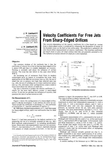
Reprinted from March 1984, Vol. 106, Journal of Fluids EngineeringJ. H. Lienhard VResearch Ass stant,Department of Chemical, Nuclear, andThermal Engineering,University of California,Los Angeles. Calif. 90024J. H. Lienhard (IV)Professor of Mechanical Engineering,University of Houston,Houston. Texas 77004.Fellow ASME'Velocity Coefficients For Free JetsFrom Sharp-Edged OrificesThe viscosity-dependence of the velocity coefficient for a free liquid jet, issuingfrom a sharp-edged orifice, is predicted by computing the dissipation of energy inthe boundary layer on the back of the orifice plate. The prediction is upheld by theonly known direct measurements of velocity coefficients. The resulting coeflcientsare much closer to unity for large orifices than they are generally assumed to be.The influence of surface tension on small jets is also explained.ObjectiveThe common wisdom of the textbooks has it that thecoefficient of velocity for a free jet leaving sharp-edged orificeis about 0.98 and that it is weakly dependent on viscosity.Nothing is normally said about the influence of surfacetension. The issue has lain fallow in this state since beforeWW 11.An increasing use of miniature fluid flows in moderntechnologies gives us reason to re-examine this issue. Suchapplications as the IBM ink-jet printer (see e.g. [I]), the use ofsmall free jets to achieve very high heat removal rates (seee.g., [2]), the use of colliding jets to create combustion sprays(see e.g. [3]), and many other configurations create a need toknow more about the velocity of small jets.Our aim is therefore to predict the velocity coefficient, C,.,chiefly for the most basic delivery system- a sharp-edgedorifice. T o d o this we calculate the influence of viscosity, andquestion the role of surface tension as well.On Measurements of C ,Figure 1 shows the configuration of a sharp-edged orifice,and of a Borda mouthpiece. It also defines the terms we use.These include the coefficient of discharge, C,; the coefficientof contraction, C,; and the coefficient of velocity, C,.By 1908 many detailed measurements of C, had been madefor sharp-edged orifices, and it was well-known that for idealflows:Some C,'s had been measured by the ballistic method or bymeasuring the rise of a vertically oriented jet (see e.g., ['I].)Both methods underestimated C, by including aerodynamiclosses. Direct pitot tube measurements were not very accurate.Often C, was reported as C,/C,, where C, had been obtainedwith calipers or simply assumed to be 0.611. It was not un-Contributed by the Fluids Engineering Division of THEAMERICANSOCIETYOFME HAN CENGINEERSALand presented at the 7th Annual/Energy-SourcesTechnology Conference and Exhibition, New Orleans, La., Feb. 11-17, 1984.Manuscript received by the Fluids Engineering Division, August 2, 1983. PaperNo. 84-FE-3.Journal of Fluids Engineeringvolume f l o w rote' ores,,,,,,,'DC, 'vCcarea,,, /area,,,,,,,C, r v , / mareae,Sharp-edped a i j c eFig. 1f:D;Borda mwthpteceConfiguration and definition of termscommon to report the assumption that C, was 0.97 or 0.98.This state of affairs is clearly reported in [4].In 1908 Judd and King [5] conducted a remarkably accurateexperiment in which they independently measured: CD with acatch tank, C, with a micrometer calipers, and C, with adifferential pitot tube-one that compared the dynamicpressure, in traverses across the jet, with static pressureupstream. The three measurements satisfied C D C , C , veryclosely. For D , 3 2 in. and h 3 1 0 ft they obtained0.99995 C, 2 0.99999, and all their C, values exceeded0.9995.Subsequent measurements of C, culminated in the work ofMedaugh and Johnson [6] who used a 1 in. orifice and foundthat C, approached 0.595 at high heads. Unfortunately Juddand King measured C, closer to 0.61 in their 1 in. orifice.Even though their largest orifice also gave C, 0.595, thecomparison of their 1 in. orifice data with Medaugh andJohnson's results had the unfortunate effect of impugningtheir otherwise good work.Medaugh and Johnson actually pointed out that C, ishighly susceptible to any minor malformation of an orifice.This explains why Judd and King's smaller orifice gave highervalues of both C, and C, even though their measurementswere accurate.A careful reading of the literature up to 1940 thus showsMARCH 1984, Vol. 106113
(2b.) rate of work done by C.V. on atmosphere at exit.(3.) rate of outflow of kinetic energy(4a.) rate of work done on C.V. by surface tension(4b.) rate of outflow of surface energy(5.) rate of viscous dissipation.that for large accurately-shaped sharp-edged orifices underhigh headsCc e0.595andC,, 1.0000(2)while the textbooks have reportedCc 0.611andC, 1 0 . 9 8Terms (2a. and 4a.) cancel (26.) and (4b.) so we are left withWe next undertake to make a prediction of C, that willreproduce Judd and King's data and apply to much smallerorifices as well. We presume that C, fn ( D o , gh, a, p, p ) , sothe prediction should take the dimensionless form:C, f(Re, We)where we use the ideal jet velocity,a,to define:(3)and where it remains to be seen whether We really influencesC, .Mechanical Energy BalanceOur analysis is based on conservation of mechanicalenergy. By constructing the balance among incoming,outgoing, and dissipated mechanical energy we are able todetermine the roles of viscosity and surface tension inretarding a liquid jet issuing from a sharp-edged orifice.We consider a control volume (C.V.) surrounding a sharpedged orifice, with liquid entering far above the orifice andexiting at a downstream point in the jet, where contractionhas been fully completed. Denoting the volume flowrate as Qand the ambient pressure asp,, we have: rate of mech. energy out rate of visc. dis.For the circular orifice this takes the form:where the significance of the terms is as follows:ficL, J 1 - 2ErReynolds No., e p Dao / p JZgh Do/vWeber No., We p(2gh)Do / arate of mech. energy in pghQ (pv, / 2 ) E,(4)Thus, no net pdVisand there isno neteffect of surface tension. Using vj2 CL,2(2gh), we canrearrange equation (4) as(5where E, pghQ is a characteristic kinetic energy associatedwith the liquid efflux (note that the square of the ideal jetvelocity is 2gh). This is the desired expression for C,.However, before evaluating E,, we should consider morecarefully the surprising disappearance of surface tension.The Influence of Surface TensionOur energy accounting shows the clean cancellation of thesurface energy outflow and work done by surface tension inthe contracted portion of the jet before Rayleigh breakupoccurs. Yet net surface energy is carried away. We thereforelook for the exchange between kinetic energy and surfaceenergy to be made where Rayleigh breakup occurs, but notbef0re.l The overall surface energy of the finite unbrokenlength of a jet stays more-or-less the same once the jet and itsbreakup length are established; and a continuous exchange ofsurface tension work with surface energy takes place within it.However in the breakup portion, wavy segments are nippedoff on the downstream side, creating an unbalanced force o nthe upstream side until it is too nipped off. The absence of thedownstream surface tension force prevents the upstreamtransfer of surface tension work which allowed the surfaceenergy to be smoothly transported downstream withoutaffecting the jet. The only influence surface tension can haveon the jet velocity, is that of retarding the droplets duringbreakup.-( I .) rate of potential energy into C.V.(2a.) rate of work done on C.V. by atmosphere on top.' W e are most grateful to Lloyd M. Trefethen [7] for extremely helpfuldiscussions in which he helped us t o see through this paradoxical situation.NomenclatureC constant in U(r) CrmC.V. control volumeC,,C,,C, coefficients of contraction, discharge, andvelocity defined in Fig. 1Cud coefficient of velocitybasedondropletvelocity, v dDo,D, diameters of orifice andof contracted jet (seeFig. 1)E, a characteristic rate ofkinetic energy flow in ajet, pghQE, rate of dissipation ofenergy as a result of thejetf (7) dimensionless streamfunction (see equation(1 1))g gravitational body forceper unit massh head141 Vol. 106, MARCH 1984constant which definesaxisymmetric bodyshape: ro a r kconstants defined inequations (16) and (18)constants in U ( r ) Crmambient pressureflow rate (m3/s in 3-dimcase, m 2 / s in 2-dim case)coordinates along thesurface of an axisymmetric body in thedirection of flow, andnormal to itradius of revolution ofan axisymmetric bodyReynolds number,D J vvelocity of flow justoutside of a boundarylayerr and y velocity componentsvolumeactual velocity of jet;actual velocity ofdroplets after RayleighbreakupWebernumber,PDO(2gh / aa positive constant inequations (11) and (12)which takes the form2k 1similarityparameterdefined by equation (12)viscosity;kinematicviscosity p l pdensity of liquidsurface tensionTransactions of the ASME
We can clarify this by balancing mechanical energy over aC.V. containing only the portion of the jet undergoingvaricose instability, The net rate of energy inflow from upstream is (pghQ-E,), and (with the other end of the C.V.beyond the end of the jet) the net outflow is zero. The dropletsthen store kinetic and surface energies at the ratewhere u , is the droplet velocity. No net work is done and weneglect any viscous dissipation by the surface waves. If we letC , , udthen some algebra givesFig. 2Potential flows for boundary analyses/a,The Influence of Viscous DissipationWe now return to the problem of evaluating E,, the rate ofviscous dissipation o f energy, which must be known in orderto evaluate either C , or C , , .The viscous dissipation is obtained by integrating the in,andcompressible dissipation function, C c ( a / a y ) overthrough the volume, V, o f the boundary layer (see notation inFig. 2.). Thusfor a circular jet. The same logic givesfor a slot jet, where C, for a slot is Dl/Do instead of(Dl /Do)2. As anticipated, the effect of surface formation is toretard the droplets formed at breakup.This situation is quite evident when we view the breakup ofwater bells created by the coaxial collision of two equal jets atmodest values of We. (See, e.g., the photographs in [a]). Theresulting sheets (or water bells) spread out very thin but theysuffer no reduction of velocity until surface forces exactlybalance momentum. Then the large beads of liquid that formare observed to leave with a much reduced velocity.Thus, while equations (6) and (7) apply to the drops formedwhen the jets break up, they d o not apply to the unbroken jet,and C,, f fn(We). Conversely, when the sum of the rates ofcreation of surface energy and of viscous loss exceed the rateof supply of potential energy, the radicals in equations ( 6 ) and(7) become imaginary, signifying that liquid can no longerescape from the orifice. As this condition approaches, thebreakup region moves upstream toward the orifice, we losethe well-defined region of full contraction, the surface forcesbecome increasingly dominant (We decreases), and C,,finally reaches zero when the jet can no longer flow freely.T o check this limiting behavior, Chen [9] ran the followingexperiment: He glued standard 0.65 mm, 0.749 mm, and 1.50m& ASME sharp-edged brass orifices to the bottom of a 20mm ID vertical graduated tube. Water inflow to the tube wasregulated to give a very slowly falling head. When the vertically issuing jet stops flowing freely and starts chugging, wecall C , , O. At that point, water can only escape byrepeatedly wetting the metal outside the hole and oozing out.The only significant "error" in this experiment is that relatedto identifying the exact point which chugging begins. Thatuncertainty is about & 10 percent.The results of the experiments were as follows (we neglectE, since there can be no dissipation when there is no flow.):Do(rnm)0.650.7941.50minimum h (mm)for steady flow1We - D0(2gh)302513u7.957.767.731C , ifweJC, 81.011.061.07T o evaluate this integral we must findin the boundarylayer. The axisymmetric boundary layer equations arewhere ro ro(r) is the radius of revolution of body on whichthe boundary layer lies and r is the coordinate along thesurface (ro r for the orifice plate). The pressure gradientterm (see Fig. 2) becomes:if we use the far-field velocity distribution along the wall.It is easy to show that the velocity potential at the wall for atwo-dimensional slot flow (as given, for example, in [lo]) hasexactly the far-field form ( U ( r ) Q / r r ) all the way up to thelip. We have presumed that this is also the case for flowthrough a circular hole.Axisymmetric boundary layer flows for which U ( r ) Cr"are self-similar under the transformation (r,y)- (r,q), withthe stream function:and the similarity variable:q y(*aU/vr)'"where: a is an arbitrary constant, greater than zero; weconsider r o a r k (where k is a constant); and the minus signapplies when the constant, C , is negative. If a is chosen as2k 1, we obtain the f ( q. ) appropriateto the Falkner-Skan.flow for which Uar""" (see e.g., Batchelor [13], Sect. 5.9;White [I Sect. 4-3, 4-9,)Equation (8) now becomes-The results verify that surface tension throttles the flow as wewould expect it to do. The fact that C, is on the order of unityis consistent with our understanding that contraction iscompletely suppressed in small enough orifices and slowenough flow rates.Journal of Fluids EngineeringE, PI,,[U(r)I2q: V " ' ) ) d v(13)MARCH 1984, Vol. 1061 15
head1.0i51510. rn2025Combining equations (13), (14), and (15), and using variouspreceding definitions, we get37487-7777 ?00where0for the circular holeK , 0.457316for the slot(17)For the slot, ro constant -03 and we recover a well-knownJeffrey-Hamel wedge flow (see e.g., [ l l ] Sect. 3-8.7). For thecircular hole, ro r a n d we obtain a nonlinear ordinary d.e. inf (7). (The latter case is included by Crabtree, Kiichmann, andSowerby [12].)The dissipation integral was evaluated numerically for bothcases, giving0C"equatlon ( 19 )0 9999,K , 0.4948720.242738 for the holeK K , v (. 84832I I ) )for theslot [ (18) where the estimated accuracy of K, is at least 5 significantfigures. Thus099991An easy calculation shows that 99 percent of the viscousloss occurs within 1.36 diameters of the edge of the circularhole (4.50 diameters for the slot), so that our infinite plateanalysis is valid for fairly small plates if they have the appropriate potential flow.equatlon ( 19 )ResultsWe thus advance equation (19) as the correct expression forC,, for jets leaving slots and orifices, before any air drag ordroplet breakup has occurred. The expressions cannot beapplied belowWe 09 9 9 602040IL6080J100head. f fFig. 3Comparison of equation (19) with the data of Judd and Kingand d V can be transformed with2 r d r d y 2 aIJ(r,7) lrdrdtlfor the circular hole[ 48for a circular holefor a slotEquation (19) requires knowledge of C . , however its influenceis secondary. At high values of Re it is adequate to guessC c 0 . 6 , and even to simplify the computation by takingC D C , under the radical, although we have made no suchsimplifications here.Equation (19) is compared with Judd and King's data inFig. 3. The comparison is good within the variability of thedata but that variability is clearly large. We should be awarethat Judd and King's C,, data depended on measurements ofdifferential heads on the order of (1/20) in. of water, withmanometer deflections on the order of (1/2) in. If we bear inmind that both the prediction and the data focus on 1 - C:,then we recognize that the prediction lies among the datawhile the conventional value of (1 -0.9g2) is high by a factorof 1000. Equation (19) is thus the surest prediction of C,:presently available, and probably is more accurate than anyexisting data.It is worth noting that the Borda mouthpiece (see Fig. 1)offers very little way in which any viscous dissipation couldoccur, since very little of the liquid approaches the hole over awall. It is well-known (see e.g., [4]) that for a Bordamouthpiece1 drdy 1 IJ(r,7) ldrdtlfor the slot (per unit depth).and the Jacobian is evaluated as1IJ(r,v) I IJ(r,y) I - ' VY161Vol. 106, MARCH 1984(15)Since C, must be very close to unity for virtually any Bordaflow, we anticipate that C , and Cn will be equal to 1/2 for aperfectly shaped mouthpiece.Unfortunately no existing data for the Borda MouthpieceTransactions of the ASME
*have accuracy higher than about2 percent thus we cannotverify this prediction. Furthermore C, a n d C,. for BordaMouthpieces, like those for sharp edged orifices, arevulnerable t o minor machining defects in the vicinity of thelip.Conclusions1. Surface tension does not retard a liquid jet unless itcompletely stops it (see Conclusion 2). However it will retardthe broken-up droplets approximately according t o equation( 5 ) o r (6).2. When We48/\ICr any circular liquid jet flow will bechoked off. When W e 4 / C r a slot flow will be chokedoff.3 . C , for a sharp-edged circular orifice o r for a sharpedged slot is given by equations (19) a n d (20).4. C , equals unity within 0.1 percent for almost anyaperture for which Re 10,000.ReferencesI The entire iswe of the January, 1977 IBMJour. Res. andDev. is devotedto the dynamics of small jets, Vol. 21. No. I . 1977.Journal of Fluids Engineering2 Monde, M.,a n d Karto. Y., "Burnout In High Heat-Flux Boiling Sysremwith an Impinging Jet." Inf. J. Hear Mass A n s f e r .Vol. 21, 1Y78, pp.295-305.3 Brodhey, R. S., The Phenomena o f Fluid Molions, Addison-Wesley,Reading. Mass., 1967.4 Encyclopaedia Brirannica. I Ith ed, Encyclopaedia Britannica Inc. NewYork, 191 1, Articleon "Hydraulics," pp. 38-56.5 Judd, H . , and King, R . S., "Some Experiments o n the FrictionlessOrifice," Engr. News, Vol. 56, No. 13, 1908, pp. 326-330.6 Medaugh, F . W . , and Johnson, G . D., "Investigation of the DischargeCoefficients of Small Circular Or fices," Civil Engr., Vol. 7 , No. 7, 1940, pp.422-4.7 Trefethen, Lloyd, M . . private communicarions.8 Huang, J . C . P., "The Breakup of Avisymmetric Liquid Sheets," J.FluidMech., Vol. 43, Parr 2, 1970, pp. 305-319.9 Chen, Y . , unpubl shedinitiative project for course M E C E 7397, Mech.Engr. Dept., Univ. of Houston, fall, 1981.10 Birhhoff, G . , and Zaranronello, E . H., Jeo, Wakes and Caviries.Academic Press. New York, 1957, S e c t o n11-5.11 White, F . M . , ViscousFlfridFlow,McGraw-Hill, New York, 1974.12 Crabtree, L. F . , Kuchemann, D. a n d Sowerby, L., "Three-DimensionalBoundary Layers." Chaprer VI11, Sect. 9. Laminar Boundary Layers (L.Rosenhead, ed.) Oxford University Press, 1963.13 Batchelor. G . K. A n Inrroducrion ro Fluid Dynamics, CambridgeUniversity Press. 1967.MARCH 1984, Vol. 106117
C constant in U(r) Crm C.V. control volume C,,C,,C, coefficients of con- traction, discharge, and velocity defined in Fig. 1 Cud coefficient of velocity based on droplet velocity, vd Do,D, diameters of orifice and of contracted jet (see Fig. 1) E, a characteristic rate of kinetic energy flow in a jet, pghQ