Transcription
INTRODUCTIONOVERVIEWThank you for purchasing the Minn Kota i-Pilot Link . This revolutionary boat control system enables your Minn Kota trollingmotor and your Humminbird Fishfinder to communicate with each other, delivering unprecedented levels of automatic navigation.Find, store, and revisit your most productive fishing spots and tracks, taking control of it all from either the i-Pilot Link wireless remotecontrol or directly from the Humminbird Fishfinder. Add an i-Pilot compatible Humminbird LakeMaster digital map card and unlockthe ability to automatically follow depth contours for even higher levels of boat control. All with GPS accuracy so you spend less timepositioning your boat and more time catching fish.This i-Pilot Link Owner’s Manual is divided into four main sections: Installation, Getting Started, Manual Control, and GPS MotorControl. A waterproof and easy-to-read Quick Reference Guide is included as a supplement to the User Manual.A French version of the manual is available online at minnkotamotors.comUne version français du manuel est disponible en ligne à minnkotamotors.comSAFETY AND CAUTIONSYou are responsible for the safe and prudent operation of your vessel. We have designed i-Pilot Link to be an accurate and reliable toolthat will enhance boat operation and improve your ability to catch fish. This product does not relieve you from the responsibility for safeoperation of your boat. You must avoid hazards to navigation and always maintain a permanent watch so you can respond to situationsas they develop. You must always be prepared to regain manual control of your boat. Learn to operate your i-Pilot Link in an area freefrom hazards and obstacles.WARRANTY AND REGISTRATIONTo receive all the benefits of your product warranty please fill out and mail the warranty registration card. You may also register yourproduct online at minnkotamotors.com.Correctly installing i-Pilot Link on a Minn Kota trolling motor will not void the original motor warranty or the warranty of any previouslyinstalled accessories. Installing i-Pilot Link will not extend the warranty of any Minn Kota product it is being installed into or inconjunction with.TRADEMARKSMinn Kota , Riptide , i-Pilot , AutoPilot , CoPilot , Link , PowerDrive , Terrova , Ulterra are trademarked by or registeredtrademarks of Johnson Outdoors Marine Electronics, Inc.The i-Pilot installation will require permanently removing the motorcontrol box cover. This cover includes information about yourmotor that may be needed for future service work or when orderingreplacement parts. Please note the information from your motor in thespace provided below.Motor model (circle one) Terrova ST PowerDrive V2 SPAuto Pilot (Yes or No)Motor thust (55lb, 70lb, etc)2 minnkotamotors.com 2015 Johnson Outdoors Marine Electronics, Inc.
GETTING STARTEDTABLE OF CONTENTSWarranty and WarningsInstallationParts List4-56-196-7Preparing for Installation8Installation of i-Pilot Link9-19Getting Started20-30Knowing Your Remote20-21Controls Menu22-25Remote BatteryController OperationsSystem StartupUpdate Software2626-282829-30i-Pilot Link Setup31-33Manual Control34-35GPS Motor 48BackTrack49Follow The Contour50-52Route Navigation53-55-AutoPilot /Advanced AutoPilot56-60Cruise ControlData ManagementFrequently Asked mpliance Statements70Notes71 2015 Johnson Outdoors Marine Electronics, Inc.minnkotamotors.com 3
TWO-YEAR LIMITED WARRANTYWARRANTY ON MINN KOTA i-PILOT AND i-PILOT LINK WIRELESS GPSTROLLING SYSTEM ACCESSORYJohnson Outdoors Marine Electronics, Inc. (“JOME”) extends the following limited warranty to the original retail purchaser only. Warranty coverage is nottransferable.MINN KOTA LIMITED TWO-YEAR WARRANTY ON THE ENTIRE PRODUCTJOME warrants to the original retail purchaser only that the purchaser’s new Minn Kota i-Pilot or i-Pilot Link Wireless GPS Trolling System Accessory willbe materially free from defects in materials and workmanship appearing within two (2) years after the date of purchase. JOME will (at its option) either repairor replace, free of charge, any parts found by JOME to be defective during the term of this warranty. Such repair, or replacement shall be the sole and exclusiveliability of JOME and the sole and exclusive remedy of the purchaser for breach of this warranty.EXCLUSIONS AND LIMITATIONSThis limited warranty does not apply to products that have been used commercially or for rental purposes. This limited warranty does not cover normal wearand tear, blemishes that do not affect the operation of the product, or damage caused by accidents, abuse, alteration, modification, shipping damages, actsof God, negligence of the user or misuse, improper or insufficient care or maintenance. DAMAGE CAUSED BY THE USE OF OTHER REPLACEMENTPARTS NOT MEETING THE DESIGN SPECIFICATIONS OF THE ORIGINAL PARTS WILL NOT BE COVERED BY THIS LIMITED WARRANTY.The cost of normal maintenance or replacement parts which are not in breach of the limited warranty are the responsibility of the purchaser. Prior to usingproducts, the purchaser shall determine the suitability of the products for the intended use and assumes all related risk and liability. Any assistance JOMEprovides to or procures for the purchaser outside the terms, limitations or exclusions of this limited warranty will not constitute a waiver of the terms, limitationsor exclusions, nor will such assistance extend or revive the warranty. JOME will not reimburse the purchaser for any expenses incurred by the purchaserin repairing, correcting or replacing any defective products or parts, except those incurred with JOME’s prior written permission. JOME’S AGGREGATELIABILITY WITH RESPECT TO COVERED PRODUCTS IS LIMITED TO AN AMOUNT EQUAL TO THE PURCHASER’S ORIGINAL PURCHASEPRICE PAID FOR SUCH PRODUCT.HOW TO OBTAIN WARRANTY SERVICETo obtain warranty service in the U.S., the product believed to be defective, and proof of original purchase (including the date of purchase), must be presentedto Minn Kota’s factory service center in Mankato, MN. Any charges incurred for service calls, transportation or shipping/freight to/from the factory, labor tohaul out, remove, re-install or re-rig products removed for warranty service, or any other similar items are the sole and exclusive responsibility of the purchaser.Products purchased outside of the U.S. must be returned prepaid with proof of purchase (including the date of purchase and serial number) to any AuthorizedMinn Kota Service Center in the country of purchase. Warranty service can be arranged by contacting the factory at 1-800-227-6433 or email service@minnkotamotors.com. Products repaired or replaced will be warranted for the remainder of the original warranty period [or for 90 daysfrom the date of repair or replacement, whichever is longer]. For any product that is returned for warranty service that JOME finds to benot covered by or not in breach of this limited warranty, there will be a billing for services rendered at the prevailing posted labor rate andfor a minimum of at least one hour.NOTE: Do not return your Minn Kota product to your retailer. Your retailer is not authorized to repair or replace products.THERE ARE NO EXPRESS WARRANTIES OTHER THAN THESE LIMITED WARRANTIES. IN NO EVENT SHALL ANY IMPLIEDWARRANTIES INCLUDING ANY IMPLIED WARRANTIES OF MERCHANTABILITY OR FITNESS FOR PARTICULAR PURPOSE, EXTENDBEYOND THE DURATION OF THE RELEVANT EXPRESS LIMITED WARRANTY. IN NO EVENT SHALL JOME BE LIABLE FOR PUNITIVE,INDIRECT, INCIDENTAL, CONSEQUENTIAL OR SPECIAL DAMAGES. Without limiting the foregoing, JOME assumes no responsibility forloss of use of product, loss of time, inconvenience or other damage.Some states do not allow limitations on how long an implied warranty lasts or the exclusion or limitation of incidental or consequential damages, so the abovelimitations and/or exclusions may not apply to you. This warranty gives you specific legal rights and you may also have other legal rights which vary from stateto state.4 minnkotamotors.com 2015 Johnson Outdoors Marine Electronics, Inc.
HUMMINBIRD WARNINGSHUMMINBIRD WARNINGSWARNING! This device should not be used as a navigational aid to prevent collision, grounding, boat damage, or personal injury. When the boat is moving, waterdepth may change too quickly to allow time for you to react. Always operate the boat at very slow speeds if you suspect shallow water or submerged objects.WARNING! The electronic chart in your Humminbird unit is an aid to navigation designed to facilitate the use of authorized government charts, not to replace them.Only official government charts and notices to mariners contain all of the current information needed for the safety of navigation, and the captain is responsible fortheir prudent use.WARNING! Humminbird is not responsible for the loss of data files (waypoints, routes, tracks, groups, recordings, etc.) that may occur due to direct or indirectdamage to the unit’s hardware or software. It is important to back up your control head’s data files periodically. Data files should also be saved to your PC beforerestoring the unit’s defaults or updating the software. See your Humminbird online account at humminbird.com and the Waypoint Management Guide on yourHumminbird Manual CD for details.WARNING! Do not travel at high speed with the unit cover installed. Remove the unit cover before traveling at speeds above 20 mph.WARNING! Disassembly and repair of this electronic unit should only be performed by authorized service personnel. Any modification of the serial number orattempt to repair the original equipment or accessories by unauthorized individuals will void the warranty.WARNING! This product contains chemicals known to the State of California to cause cancer and birth defects or other reproductive harm.ATTENTION INTERNATIONAL CUSTOMERS: Products sold in the U.S. are not intended for use in the international market. Humminbird internationalunits provide international features and are designed to meet country and regional regulations. Languages, maps, time zones, units of measurement, and warrantyare examples of features that are customized for Humminbird international units purchased through our authorized international distributors. To obtain a list ofauthorized international distributors, please visit our Web site at humminbird.com or contact Humminbird Customer Service at (334) 687-6613.NOTE: The illustrations in this manual may not look the same as your product, but your unit will function in the same way.NOTE: Some features discussed in this manual require a separate purchase, and some features are only available on international models. Every effort has beenmade to clearly identify those features. Please read the manual carefully in order to understand the full capabilities of your model.NOTE: To purchase accessories for your control head, visit our Web site at humminbird.com or contact Humminbird Customer Service at 1-800-633-1468.NOTE: The procedures and features described in this manual are subject to change without notice. This manual was written in English and may have been translatedto another language. Humminbird is not responsible for incorrect translations or discrepancies between documents.NOTE: Product specifications and features are subject to change without notice.NOTE: Humminbird verifies maximum stated depth in saltwater conditions, however actual depth performance may vary due to transducer installation, water type,thermal layers, bottom composition and slope.NOTE: The maximum number of iTracks, Spot-Locks, waypoints, routes, and tracks may vary due to the setup of your Waypoint Management directory. Groups andsub-groups also use storage, and the storage limit is influenced by the complexity of your Waypoint Management directory. See your Waypoint Management Guidefor details.TRADEMARKS700 Series , 800 Series , 900 Series , 1100 Series , AutoChart , HumminbirdPC , Humminbird , LakeMaster , ONIX , Side Imaging , X-Press Menu, andZeroLine Map Card are trademarked by or registered trademarks of Johnson Outdoors Marine Electronics, Inc. 2015 Johnson Outdoors Marine Electronics, Inc.minnkotamotors.com 5
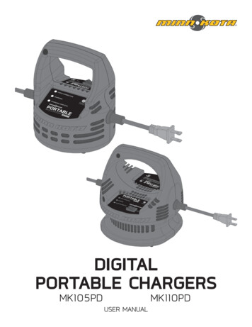
INSTALLATIONPARTS LIST VIEW TERROVA & RIPTIDE ST6 90280HEAD ASSY, IP2 (TERROVA)12990281HEAD ASSY, IP2 (RIPTIDE ST)212994180REMOTE ASSY, i-PILOT LINK312370712BATTERY, LIPO PACK412374637O-RING, BATTERY SEAL512376421DOOR, BATTERY642383442SCREW-3MM X .5 PPH MACHINE712994907BAG ASSY, i-PILOT LINK,TRRV842372100SCREW-#8-18 X 5/8 THD* (SS912370817LANYARD,RMT W/CARABINER1012224704INSERT-PLUG, BLK, i-PILOT LINKTIE WRAP,BLACK,UV RESIST.NYLON11523763121212994909BAG ASSY, i-PILOT LINK, POWER1312373241CABLE, USB REMOTE CHARGER1412375900ADAPTER, USB POWER PORT1512377156MANUAL-CD, i-PILOT LINK1612377155MANUAL QCK REF, i-PILOT CABLE, ETH (M12-M-M12-F, 30’) 2015 Johnson Outdoors Marine Electronics, Inc.
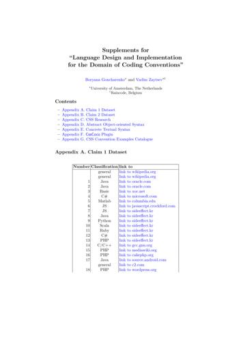
INSTALLATIONPARTS LIST VIEW POWERDRIVE V2 & RIPTIDE SP 2015 Johnson Outdoors Marine Electronics, Inc.ITEMQTYPARTNUMBERDESCRIPTION112990282HEAD ASSY, V2, IP2 (POWERDRIVE)12990283HEAD ASSY, SP, IP2 (RIPTIDE)212994180REMOTE ASSY, i-PILOT LINK312370712BATTERY, LIPO PACK412374637O-RING, BATTERY SEAL512376421DOOR, BATTERY642383442SCREW-3MM X .5 PPH MACHINE712994908BAG ASSY, i-PILOT LINK, V2842372100SCREW-#8-18 X 5/8 THD* (SS912370817LANYARD, RMT W/CARABINER1012376716PLUG, STRAIN RELIEF V2/SP1122332104SCREW-1/4-20 X 5/8 S/S1252376312TIE WRAP, BLACK, UV RESIST.NYLON1342375403HEATSHRINK .375X2 ADHV LINED1412994909BAG ASSY, i-PILOT LINK, POWER1512373241CABLE, USB REMOTE CHARGER1612375900ADAPTER, USB POWER PORT1712377156MANUAL-CD, i-PILOT LINK1812377155MANUAL QCK REF, i-PILOT LINK191490389-1CABLE, ETH (M12-M-M12-F, 30’minnkotamotors.com 7
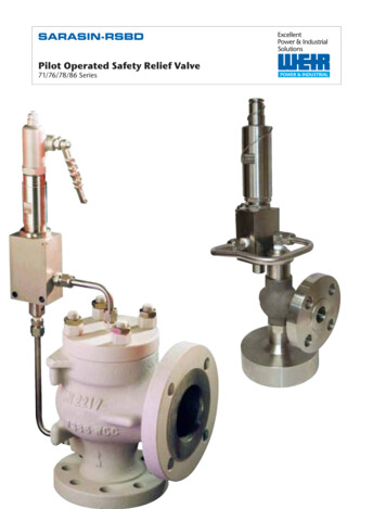
INSTALLATIONPREPARING FOR INSTALLATIONTOOLS YOU WILL NEED DURING INSTALLATIONTerrova and Riptide ST Phillips screwdriverPowerDrive V2 and Riptide SP Phillips screwdriver Needle-nose pliers Utility knife Heat gun or other heat source for installing heat shrinkTo help with future service work or ordering replacement parts, please refer to the information box in the Notes section located onthe back pages of this manual.Before installing i-Pilot Link on your motor, make sure the trolling motor is properly installed on your boat. Find a clean and drylocation for performing the installation.Most importantly, disconnect all power to the trolling motor before installation. Not only will this protect you but also the sensitiveelectronics you are about to install.Read through the entire installation process before performing the installation.If you need help or need further instruction on installing i-Pilot Link, please call Minn Kota technical service at 1-800-227-6433 totalk to a customer service representative.HUMMINBIRD FISHFINDERDepending on your Humminbird model and system configuration, you may need topurchase additional cables, as shown below. For the latest compatibility informationand to purchase accessories, visit our Web site at humminbird.com or contactHumminbird Customer Service. If the Ethernet port on your Humminbird Fishfinder is round, the Ethernetcable can be connected directly to the Fishfinder without an adapter cable. If the Ethernet port on your Humminbird Fishfinder is shaped like anhourglass, you will need to purchase the AS EC QDE Ethernet Adapter Cable. Extension Cables are available for the Ethernet Cable if you need to extend theconnection longer than the 30 feet provided. See humminbird.com for details.8 minnkotamotors.comCHECK THE ETHERNET PORT ON YOURHUMMINBIRD port 2015 Johnson Outdoors Marine Electronics, Inc.
INSTALLATIONINSTALLATION OF i-PILOT CONTROLLERFor PowerDrive V2 and Riptide SP trolling motors go to page 11.i-PILOT LINK INSTALLATION ON TERROVA AND RIPTIDE ST TROLLING MOTORSNOTE: i-Pilot Link will override all CoPilot functionality. CoPilot remotes will not functionwith i-Pilot Link.NOTE: The Terrova foot pedal is fully functional and supported when i-Pilot Link isinstalled correctly.1. Disconnect all power to the trolling motor.2. Remove control box cover screws and cover using Phillips screwdriver. (Figure 1)3. If the trolling motor has the AutoPilot feature, unplug the AutoPilot control boardand remove it from the control box. (Figures 2 and 3)FIGURE 1FIGURE 2FIGURE 34. Remove grommet by pulling back on coil cord strain relief and pushingdown on grommet. (Figure 4)Grommet5. Route the Ethernet cable through the grommet hole and through thecenter of the coil cord. (Figure 5)FIGURE 4FIGURE 5 2015 Johnson Outdoors Marine Electronics, Inc.minnkotamotors.com 9
INSTALLATION6. Plug the i-Pilot Link controller connector into the accessoryconnector as shown. (Figure 6) Be careful to orient connector properly prior topushing together. The plug will click twice when pushing it together and the yellowend will be fully covered when installed properly. Make sure connector is aligned properly. (Figure 7) Ensure connector is fully seated as shown. (Figure 7)7. Install new grommet supplied with i-Pilot Link by snapping it into the hole located infront of the coil cord strain relief. (Figure 8)8. Place the i-Pilot Link controller where the control box cover was installed andsecure with supplied #8 screws. Do not over tighten screws. (Figure 9)FIGURE 69. i-Pilot Link is now installed on the motor. Skip ahead to page 17 to verify theinstallation.FIGURE 7FIGURE 8FIGURE 910 minnkotamotors.com 2015 Johnson Outdoors Marine Electronics, Inc.
INSTALLATIONINSTALLATION OF i-PILOT CONTROLLERi-PILOT LINK INSTALLATION ON POWERDRIVE V2 AND RIPTIDE SPNOTE: Once i-Pilot Link is installed in a PowerDrive V2 or Riptide SP motor,the foot pedal cannot be used again unless i-Pilot is fully uninstalled.1. Disconnect all power to the trolling motor.2. If a CoPilot is installed, it must be removed as follows:a. Disconnect motor connector and foot pedal connector from CoPilot.(Figure 10)FIGURE 10b. Remove the CoPilot receiver from the motor by removing both mountingscrews. Do not replace these screws as the side plates will be removed in step13 of this installation. (Figure 11)3. Remove control box cover screws and cover using Phillips screwdriver. (Figure 12)4. If the trolling motor has AutoPilot it must be removed as follows:a. Disconnect all six AutoPilot connectors from AutoPilot controller, using aneedle-nose pliers and a utility knife to remove any heat shrink insulation thatmay exist. (Figure 13)FIGURE 11b. Remove the AutoPilot controller from the head of the trolling motor. (Figure14) This is done by pushing out the locking tabs then lifting the circuit boardout. Finally lift out the compass.FIGURE 12FIGURE 13FIGURE 14 2015 Johnson Outdoors Marine Electronics, Inc.minnkotamotors.com 11
INSTALLATION5. Remove grommet by pulling back on coil cord strain relief and pushing down ongrommet until it pops out. (Figure 15)6. Review the cables in the head of the trolling motor.Passe-câblea. If a sonar cable is present, it must be routed around the outer perimeter of thecontrol box. The sonar ground wire should also be routed as shown. (Figure 16)b. The motor power wires must be routed as shown. (Figure 16)SonarCableFIGURE 15Sonar Cable (Universal Sonar Motors Only)SonarGroundWirePowerWiresAutoPilot Wires(AutoPilot Motors Only)FIGURE 17FIGURE 167.Route i-Pilot Link controller cable through grommet hole and through center ofcoil cord. (Figure 17)8. If AutoPilot was removed, insulate the loose AutoPilot connectors as follows:a. For PowerDrive V2 Motors: Using a needle-nose pliers push all six AutoPilotconnectors that were disconnected in step 4 onto terminal holders located onthe underside of the i-Pilot Controller. (Figure 18)IMPORTANT: Pull on each wire to make sure it is secured properly. Loosewires can cause damage to i-Pilot Controller and the entire motor.FIGURE 18Insert AutoPilot wires into terminal holders.12 minnkotamotors.com 2015 Johnson Outdoors Marine Electronics, Inc.
INSTALLATIONAutoPilot connectors must be placed onto holders exactly as shown.(Figure 19)b. For Riptide SP Motors: Apply heat shrink insulation supplied in bag assemblyto the ends of all six loose AutoPilot connectors as shown. (Figure 20) Usea zip tie to bundle connectors together. Trim the zip tie and place connectorbundle in the middle of the control box as shown. (Figure 21)9. Install new grommet supplied with i-Pilot Link by snapping it into the hole locatedin front of the coil cord strain relief. The i-Pilot Link controller cable must be placedin the pass-through slot of the grommet. (Figure 22)FIGURE 19Pinch ends of heat shrink shutusing needle-nose pliers.10. Place the i-Pilot Link controller where the control box cover was installed. Pull anyextra controller cable out of the control box by gently pulling on the cable.(Figure 23)11. Secure cover with supplied #8 screws. Do not over tighten screws. (Figure 24)FIGURE 20Insulate and seal six AutoPilot wires onRiptide SP motors with supplied heat shrink.FIGURE 22FIGURE 23FIGURE 21Place insulated AutoPilot wires in the bottomcenter of the control box as shown.FIGURE 24 2015 Johnson Outdoors Marine Electronics, Inc.minnkotamotors.com 13
INSTALLATION12. Secure the i-Pilot Link controller cable to the motor coil cord in all threelocations shown using zip ties provided. (Figure 25) Trim zip ties using utilityknife. Failure to secure cable will result in possible damage to the cablingduring operation.13. Remove the left and right side plates of trolling motor by loosening all fourside plate screws using a Phillips screwdriver. (Figure 26)14. Remove center housing by pushing in on both sides and lifting up at the sametime. This will expose the main control board and wiring. (Figure 27)Zip TieLocation 1Zip TieLocation 2Zip TieLocation 1FIGURE 2515. The steering motor cable passes through the top of the center housingremoved in step 14. This cable contains a black and white wire. Disconnectthese two wires by pulling each connector apart. (Figure 28) Riptide SP motors will have this connection covered with heat shrinkwhich must be removed with a utility knife.16. Loosen the cable strain relief that is secured to the base of the motor and install the i-Pilot Link controller steering cable into theopen strain relief spot. (Figure 29)FIGURE 29FIGURE 26FIGURE 27Entrance of steering cable through center housingDisconnect both wires by removing heat shrink and pulling them apart14 minnkotamotors.comFIGURE 28FIGURE 29 2015 Johnson Outdoors Marine Electronics, Inc.
INSTALLATION17. Tighten the cable strain relief as shown. The i-Pilot Link controller steering cable should slide freely through the strain relief wheninstalled properly. (Figures 30 and 31)18. Slide four pieces of heat shrink insulation over each side of the wires that were disconnected in step 15. (Figure 32)19. Connect the black and white wires from the i-Pilot Link controller cable to the back and white steering motor connected to blackand white is connected to white. (Figure 33)Foot Pedal CableReinstall strainrelief screwFIGURE 31Motor Power Cablei-Pilot Link Controller Steering CableFIGURE 30Slide heat shrinkover steeringmotor wiresConnectsteering wires:whit e to whiteblack to blackFIGURE 32FIGURE 33 2015 Johnson Outdoors Marine Electronics, Inc.minnkotamotors.com 15
INSTALLATION20. Complete the installation by positioning the heat shrink over the connections and shrink down, using a heat gun or other heatsource, being careful not to overheat any wire or parts.Seal connections with heat shrink.IMPORTANT: DO NOT OVERHEAT WIRES OR SURROUNDING PARTS WHEN INSTALLING HEAT SHRINK!21. Reinstall center housing over control board by pushing it down until the side fingerslock into place. The new i-Pilot Link Controller steering cable should be exiting thecable exit hole at the center and bottom of the center housing. (Figure 34)22. Reinstall both side plates using Phillips screwdriver. If a Co-Pilot was uninstalled,use new 1 4-20 X 5/8” Phillips screws provided. (Figure 35)23. If a foot pedal is connected to the trolling motor, it must be disconnected. Oncei-Pilot Link has been installed the foot pedal cannot be used unless i-Pilot Link iscompletely uninstalled.24. Connect i-Pilot Link controller cable to the foot pedal connector, making sure theconnector nut is tight. (Figure 36)IMPORTANT: DO NOT PLACE DIELECTRIC GREASE ORANY TYPE OFLUBRICANT IN THE CONNECTOR.25. i-Pilot is now installed on the motor. Skip ahead to the next section to verifyinstallation.FIGURE 34FIGURE 35FIGURE 3616 minnkotamotors.com 2015 Johnson Outdoors Marine Electronics, Inc.
INSTALLATIONVERIFYING INSTALLATION OF i-PILOT LINK CONTROLLER AND REMOTEIt is important to verify your i-Pilot Link installation prior to going on the water. If this cannot be done, it is highly recommended thatsystem verification be done in an open area on a calm day with a fully operational outboard motor for a backup means of poweringyour boat.To verify that i-Pilot Link is working properly before going on the water, follow the steps below.1. Trolling motor should be correctly installed and mounted to the bow of a boat.2. The boat and trolling motor must be located outside and have a direct view of the sky to obtainGPS satellite signals.3. Verify that all obstructions are away from the prop in all directions in both the stowed and deployed positions.4. Connect power to the trolling motor.5. Deploy the motor so the motor shaft is completely vertical.6. The i-Pilot Link controller will emit four short beeps on startup.7. Turn on the remote by pressing the OK key and verify the LCD comes on.8. When i-Pilot Link is powered up, it starts to gather satellite information about its location. A minimum satellite signal level mustbe achieved before all i-Pilot Link functionality is available. This minimum level is one bar on the GPS signal icon. With no barsshowing, only manual functions will be available.9. Verify all manual functions by pressingand.10. If you experience any problems with any of the steps above, or cannot obtain a GPS satellite signal, refer to thetroubleshooting section. 2015 Johnson Outdoors Marine Electronics, Inc.minnkotamotors.com 17
INSTALLATIONCONNECT THE i-PILOT LINK TO THE HUMMINBIRD FISHFINDERThe i-Pilot Link can be connected directly to the Humminbird Fishfinder or to the Humminbird Ethernet Switch (optional). If youpurchase the Ethernet Switch, install it using the instructions in the included installation guide.WARNING! The power source must be turned off before you proceed with this installation.NOTE: The Ethernet extension cable is optional for your installation. To purchase Ethernet switches, Ethernet cables, and extensioncables, visit our Web site at humminbird.com or call Humminbird Customer Service at 1-800-633-1468.1.Locate the Ethernet cable on the i-Pilot Link.2. If you are using the Ethernet extension cable for your installation, connect it to the Ethernet cable on the i-Pilot Link. Handtighten the screw nut.NOTE: The connectors are keyed to prevent reversed installation, so be careful not to force the connectors together.If you do not need the Ethernet extension cable for your installation, proceed to step 3.3.Route the cable to the Humminbird Fishfinder or the optional Ethernet Switch.Depending on the shape of the Ethernet port on your Humminbird Fishfinder, an additional ethernet adapter cable may be requiredfor the installation. Refer to your Fishfinder operations manual or see the i-Pilot Link Compatibility Chart on our Web site atminnkotamotors.com.NOTE: The cable should be routed through an established routing system on the boat, in an area with minimal interference. Inspect theselected route carefully to ensure that there are no sharp edges, obstacles, or obstructions that may damage the cables.4.Connect to the Control Head: Connect the Ethernet Cable connector to the Ethernet port on the Humminbird Fishfinder.Connect to the Ethernet Switch: Connect the Ethernet Cable connector to an available Ethernet port.5.Round Ethernet Connectors: Hand-tighten the screw nut to secure the connection.HAND-TIGHTENING THE SCREW NUT(ROUND ETHERNET CONNECTOR)screw nutThe connectors arekeyed to preventreversed installation.18 minnkotamotors.com 2015 Johnson Outdoors Marine Electronics, Inc.
INSTALLATIONVERIFYING INSTALLATION ON THE HUMMINBIRD FISHFINDERAll equipment should be connected and powered before you turn on the Fishfinder.When the i-Pilot Link is detected, an i-Pilot Link Connected message will briefly display on the screen. You can also confirm theinstallation connections using the following instructions.NOTE: If i-Pilot Link is connected during navigation, a message will display on-screen and navigation will be canceled.NOTE: A GPS Receiver is required to enable the navigation features on the Fishfinder. The Fishfinder uses the data from the GPSReceiver attached directly to it or selected from the Ethernet network.1.Press theTitle ScreenPOWER/LIGHT key on the Fishfinder.2. When the Title screen is displayed, press the MENU key to open the Start-UpOptions Menu.3.Use the 4-WAY Cursor Control key to select Normal, and press the RIGHTCursor key.4. Press and hold the VIEW key. Select System Accessory Test. Confirm thati-Pilot Link is listed as connected. It may take a minute for the equipment to bedetected.5.Press and hold the VIEW key. Select System GPS Diagnostic View. Confirmthat External GPS is displayed and the Fix Type indicates Enhanced or 3D.NOTE: If the GPS Diagnostic View or Accessory Test is not displayed in the ViewRotation, press the MENU key twice to open the Main Menu. Select the Views tab GPS Diagnostic View or Accessory Test. Change the
Update Software 29-30 i-Pilot Link Setup 31-33 Manual Control 34-35 GPS Motor Control 36-65 Spot-Lock 38-40 Waypoints 41-42 iTracks 43-48 BackTrack 49 . JOME warrants to the original retail purchaser only that the purchaser's new Minn Kota i-Pilot or i-Pilot Link Wireless GPS Trolling System Accessory will