Transcription
Minn Kota Repair Manual01/15/04Minn Kota Service ManualThis manual is designed to assist in basic trouble shooting procedures for MinnKotatrolling motors.Table of ContentsPageSafety WarningsiiTrouble Shooting TipsiiiSection 1.1-1Hand-Control Models with a Speed Coil(5-speed models)Section 2.Hand-Control Models with a Printed Circuit Board2-1(Variable-speed models)Section 3.PowerDrive (PD) Models3-1(Corded foot pedal, non-AutoPilot, non-Genesis models)Section 4.AutoPilot (PD/AP) Models(Corded foot pedal, non-Genesis models)Part I – motors prior to model year 2001Part II – 2001 and later motorsSection 5.4-1page 4-1page 4-8Cordless PowerDrives and AutoPilot Models5-1(Radio-frequency controlled models, manufactured between 1996-1999)Section 6.Foot-Control Cable Steer Models with a Speed Coil6-1(5-speed Maxxum and All Terrain units)Section 7.Foot-Control Cable Steer Models with a Control Board7-1(Variable-speed Maxxum and All Terrain units)Section 8.PowerUp Lifts, Trims, and Tilts8-1(Models manufactured between 1996-2002)Section 9.Depth Finder Interference9-1Section 10.Vantage Motors10-1Section 11.Genesis Motors11-1Section 12.Minn Kota Universal Sonar12-1Section 13.Lower Unit / Motor Assembly13-1(includes instructions to remove motor assembly from composite tube)Section 14.Engine Mount (EM) & Neptune (EP)14-1Section 15.DeckHand Electric Anchors15-1Section 16.CoPilot Wireless Accessory16-1Section 17.3X Steering17-1i
Minn Kota Repair Manual10/31/02SAFETY WARNINGS¾ To prevent possible eye injury, always wear SAFETY GLASSES while servicingmotors.¾ Remove propeller from motor during test procedures to eliminate chances of beingcut by rotating blades.¾ Do not run motor out of water for more than a minute at a time. The motorassemblies (and speed coils) are designed to dissipate heat through the motor shellinto water. The armature seals can also dry out.¾ Follow all battery charging precautions to eliminate chances of the escaping fumesexploding.ii
Minn Kota Repair Manual10/31/02Trouble Shooting Tips With all the new features and models being added to our Minn Kota line, motortroubleshooting and repair can be quite complicated. However, with circuit boardcosts rising, it is more important than ever to correctly diagnose the problem beforereplacing parts.Here are a few trouble shooting suggestions:¾ If possible, locate the failure before replacing any parts. Sometimes disassemblyfixes the problem (pinched wires, poor connections, etc ).¾ Look at the wiring as closely as you would the control board. There are as manyproblems with wires and connectors as with defective control boards. Check thecoil cords on AutoPilot models. An open wire here will look like a bad board.¾ On control boards with clear sleeves around the quick disconnects, be sure thefemale connector does not slip down beside the male connector. It may feel likethe connector went on properly, but this connection will fail.¾ For quick troubleshooting, use a 12-volt light bulb (automotive dome or brakelight) with wires and alligator clips. Clip it to the board output and vary the speedto see if the board is working. A voltmeter on the output can sometimes bemisleading. The control board needs some kind of load to work correctly.¾ If you have replaced a board in the same motor more than once, this is probably asymptom of a larger problem. Check the wiring in the lower unit. (Shorts on themotor wires will cause board failures and shorts in PowerDrive drive housings willcause foot pedal board failures.)¾ We still see control boards replaced under warranty that are NOT defective. Tohelp us control costs to all our customers and to ensure that we will honor yourwarranty reimbursement claim, please be certain the board is defective.¾ On AutoPilot motors, seldom do both boards fail at the same time. Please doublecheck.iii
Hand-Control w/Speed Coil Repair Manual10/31/02Section 1.Hand-Control Models with a Speed CoilCase I. Motor fails to operate (on any speed).Step 1. Check to ensure proper voltage. Inspect all battery connection, trolling motor plug (if installed), and any buttsplice connections in battery leadwire for corrosion and security.Step 2. Check to see if lower unit runs.A.Connect battery lead wire to battery.B.Disconnect the black battery leadwire from the switch and connect it directly to the black brush lead.C.Disconnect the red battery leadwire from the switch and touch it directly to the red brush lead.C-1.If motor does run, proceed to Step 3.C-2.If motor does not run, a problem exists in the lower unit. Check the lower unit for voltage atthe brushes, water damage, brushes not making proper contact, or an open or shortedarmature. Repair as needed and test motor for proper operation.Step 3. If unit being serviced is not a 12/24-volt model, proceed to Step 4. If unit being serviced is a 12/24-volt model,check 12/24 switch for continuity.24vTerminal AOFFTerminal C12vTerminal B(front side of switch)A.B.(back side of switch)Turn the 12/24 switch to 12-volt ON position. Check for continuity between the common “C”terminal and the “A” terminal.A-1.If no continuity is noted, replace the 12/24 switch and test motor for proper operation.A-2.If continuity is observed, proceed to Step 3B.Turn switch to 24-volt ON. Check for continuity between the common terminal (C) and terminal (B).B-1.If no continuity is observed, replace 12/24 switch and test motor for proper operation.B-2.If continuity is observed, proceed to Step 4.Step. 4 Speed switch is defective. Replace the speed switch. Test motor for proper operation.Case II. Motor operates on some speeds, not on others.Step 1. Check to see if all wires are securely attached to the proper switch terminals.Step 2. Check speed coil functionality.A.Connect battery lead wire to battery.B.Disconnect the black battery lead from the switch and connect it directly to the black brush lead.C.Disconnect the red battery lead from the switch and touch it to each colored speed coil wire at theswitch terminals, one at a time. The motor should run as you make each connection.D.If the motor fails to run as you touch any of the colored speed coil wires, the problem is either: (1) thespeed coil is faulty and needs to be replaced; or (2) the speed coil jumper wire is not connected to theback of the brush plate (in the lower unit).D-1.If the motor runs as you touch the red battery lead to some of the colored speed coil wires, butnot all the speed coil wires, the speed coil is faulty and needs to be replaced.D-2.If the motor runs as you touch the red battery lead to each speed coil wire, proceed to Step 3.Step 3. Speed switch is defective. Replace Speed switch. Test motor for proper operation.1- 1
Hand-Control w/Control Board Repair Manual01/20/04Section 2.Hand-Control Models with a Printed Circuit BoardCase I. Motor runs intermittently (cuts in and out, fails to run in either forwardor reverse, or kicks from forward into reverse).Step 1. Check to ensure proper voltage and polarity at battery (red , black -). Inspect all batteryconnections, trolling motor plug (if installed), and any butt splice connections in battery leadwire forcorrosion and security.Step 2. Check to see if lower unit runs properly.A.Connect battery lead wire to battery.B.Disconnect the black battery lead from the control board and connect it directly to the blackC.brush lead.Disconnect the red battery lead from the control board and touch it directly to the red brushlead. The motor should run.C-1.If motor does not run, a problem exists in the lower unit. Check the lower unit forvoltage at the brushes, water in the lower unit, worn brushes, or an open or shortedarmature.C-2.If the motor does run, go to Step 3.Step 3. Units with soft-pots only: Check soft-pot (P/N 2364005) on control board.A.Visually check soft-pot for collapsed dome switches or a break down of the silver conductivelayer for the speed control. If necessary, solder on replacement soft-pot (P/N 2364005) andtest motor for proper operation (per the procedure shown in Service Bulletin dated 1/12/99).Case II. Motor fails to operate.Step 1. Check to ensure proper voltage and polarity at battery (red , black -). Inspect all batteryconnections, trolling motor plug (if installed), and any butt splice connections in battery leadwire forcorrosion and security.Step 2. Check to see if all wires are securely attached to the proper control board terminals. Check forcorroded connections.Step 3. Check to see if lower unit operates.A.Connect battery lead wire to battery.Disconnect the black battery lead from the control board and connect it directly to the blackB.C.brush lead.Disconnect the red battery lead from the control board and touch it directly to the red brushlead. The motor should run.C-1.If motor does not run, a problem exists in the lower unit. Check the lower unit forvoltage at the brushes, water in the lower unit, worn brushes, or an open or shortedarmature.C-2.If the motor does run, go to Step 4.Step 4. Check control board.MODELS WITH A SOFT-POTA.Remove soft-pot from handle assembly and ensure actuator pin and actuator spring aremaking proper contact on the silver conductor layer of the soft-pot. Visually inspect soft-potfor collapsed dome switches and excess wear on silver conductive layer of soft-pot. If2- 1
Hand-Control w/Control Board Repair ManualB.01/20/04necessary, solder on replace soft-pot (P/N 2364005) and test motor for proper operation (perthe procedure shown in Service Bulletin dated 1/12/99).Operate control board manually (without handle assembly actuators). With battery and brushleads attached to proper terminals of the control board, activate switch in upper right handcorner and run fingertip around silver conductive layer. The motor should be varying inspeed as you apply pressure to the forward speed portion of the soft-pot. (As per ServiceBulletin dated 1/12/99)B-1.If there is no control board output (motor not running), replace control board.B-2.If there is control board output, but the soft-pot is worn or either of the domeswitches is bad, replace the soft-pot (solder on replacement soft-pot, P/N 2364005, perthe procedure shown in Service Bulletin dated 1/12/99). When reassembling thehandle pay close attention to ensure that the actuation spring and pin are correctlyinstalled and making contact with the soft-pot. With the new soft-pot and handlereassembled, re-test motor for proper operation.MODELS WITH A MAGNETIC ON/OFF REED SWITCHA.After rechecking that all wires are securely attached to the proper connections with propervoltage, verify the control board is defective:A-1.Check for control board output by hooking up a test light (or V.O.M. probes) toboard output terminals (consult appropriate wiring diagram). Remove handleassembly (with handle pivot and magnet rod) off potentiometer. (The magnet rodneeds to be away from the on/off reed switch.) Connect battery leads to propervoltage. Vary the potentiometer by turning potentiometer’s stem. The test lightshould vary in intensity from off to bright. If there is no control board output, themain control board is defective.Case III. Directional Indicator always stays lit (units with magnetic, on/off reedswitch only).This reed switch is usually open. With the handle bar magnet in close proximity to the reed switch, the reedswitch contacts will close and disengage power to the PWM circuit. Removing the bar magnet from closeproximity to the reed switch will open the switch contacts, energize the PWM circuit, and light the directionalindicator.A.Check to ensure that the magnet is in place in the handle pivot assembly.B.Check to ensure that the sensor bracket and on/off reed switch are in the proper position.2- 2
PowerDrive Repair Manual10/31/02Section 3.PowerDrive (PD) Models(Corded foot pedal, non-AutoPilot & non-Genesis models)Case I. Drive Housing fails to steer left or right.Step 1. Check for proper voltage and polarity. Visually check to see that all wires are attached to proper control boardterminals. Consult appropriate wiring diagram for the model and board being tested. Check for any corrodedconnections. Clean / rewire, if necessary.Step 2. Check motor with known good test foot pedal or test the original foot pedal by performing Foot Pedal PCB TestProcedure (see page 3-4).A.If test pedal properly steers motor or if the original pedal tests bad as outlined on page 3-4, thenoriginal foot pedal is faulty. Disassemble faulty pedal to inspect if actuators are properly makingcontact on foot pedal board. Visually inspect foot pedal control board for collapsed / burnt domeswitches. Replace foot pedal board, if necessary.A-1.If dome switches are burnt, check drive housing for short between either of the drive housingwires and the metal portion of the drive housing itself. To do this, use a V.O.M. to check forcontinuity between the drive housing lead and a screw on the underside of the drive housing.A-2.If a short is found, disassemble the drive housing and insulate the wire terminals at the drivehousing’s servo motor to correct the shorted condition.A-3.Reassemble the drive housing and again check for shorts.B.If test pedal does not properly steer motor or if original pedal tests okay as outlined on page 3-4, thencheck the drive housing.B-1.Connect 12-volt power source directly to drive housing leads. If drive housing does not steer,open drive housing. Inspect servo motor and drive gears for binding/lack of lubrication.Service drive housing to correct malfunction, as needed. If necessary, re-lubricate thebushing and sleeve contact surfaces with Schaeffer’s #238 Moly Ultra Supreme grease or asimilar lubricant.Case II. Motor (lower unit) fails to run or runs intermittently.Step 1. Check for proper voltage and polarity. Visually check to see that all wires are attached to proper control boardterminals. Consult appropriate wiring diagram for the model and board being tested. Check for any corrodedconnections. Clean / rewire, if necessary.Step 2. Check motor with known good test foot pedal or test the original foot pedal by performing Foot Pedal PCB TestProcedure (see page 3-4).A.If test pedal properly controls propeller speed or if the original pedal tested bad as outlined on page 34, then original foot pedal is faulty. Disassemble faulty pedal to inspect if actuators are properlymaking contact on foot pedal board. Visually inspect foot pedal control board for collapsed / burntdome switches or bad soft pot. Replace foot pedal control board, if necessary.B.If test pedal does not properly control propeller or if original pedal tests okay as outlined on page 3-4,go to Step 3.Step 3. Check to see if lower unit runs properly.A.Connect 12 volts directly to the red and black brush leads at the top of the motor shaft (in the controlbox). The motor should run. If not, a problem exists in the lower unit. Check the lower unit forvoltage at the brushes, water in the lower unit, worn brushes, or an open or shorted armature. Repairas needed. If the motor operates properly, go to Step 4.Step 4. Check for control board output by hooking up test light (or V.O.M. probes) to board output terminals (consultappropriate wiring diagram). Use known good test pedal. Connect battery leads to proper voltage. Turn thefoot pedal to CON (constant ON) and vary the speed selector. If there is no control board output, the maincontrol board is defective. Replace main control board.3- 1
PowerDrive Repair Manual10/31/02Case III. Foot pedal sticks right/left when steering.Step 1. Inspect actuators on underside of foot pedal for sand/dirt/grit.A.Disassemble and clean contaminated actuators. Replace components as required.B.Reassemble foot pedal, leave actuators dry or use a dry lubricant to avoid further contamination withsand/dirt/grit.C.NOTE: If foot pedal sticks while customer is fishing, he may simply swish the foot pedal in the waterto temporarily flush the sand/dirt/grit from the actuator surfaces.Case IV. MOM/CON switch lever will not stay down in CON position.Step 1. From the underside of the footpedal, remove the 3 screws holding the slide control and switch lever in place.A.Remove screw holding the white plastic continuous actuator in place.B.Place washer (P/N 2301731) between actuator and foot pedal base.C.Reassemble slide-control and MOM/CON switch assembly. Test for proper operation.Case V. Motor won’t steer or steers slowly at higher thrust settings.NOTE: this section applies to both PowerDrive and AutoPilot models.Step 1. Inspect all battery connections, trolling motor plug (if installed), and any butt splice connections in the batteryleadwire for corrosion and security.Step 2. Check to insure that wire of adequate gauge has been used in the boat’s trolling motor circuit. (Wiring ofinadequate gauge will result in a voltage drop to the motor and steering circuit at higher thrust settings. SeeWiring Gauge chart for recommended minimum wire sizes by amp draw and wire length, page 3-5). If, afterinsuring that all wiring and connections are good, the steering is still slow at high thrust settings, go to Step 3.Step 3. Disassemble motor to separate the drive housing from the motor and tube and bowplate extrusion assembly.A.Remove the six screws holding the top and bottom halves of the drive housing together. (Note: thetop and bottom halves of the drive housing are “pinned” together at the corners with roll pins. The twohalves will need to be pried apart.)B.Inspect the drive housing motor, paying special attention to the drive housing motor armature shaft andmotor bushings. Test run to verify proper high speed operation and RPM.C.Remove the drive housing sleeve and bushings. Thoroughly clean the bushing and sleeve contactsurfaces of all residue and old lubricant. Re-lubricate the bushing and sleeve contact surfaces withSchaeffer’s #238 Moly Ultra Supreme grease or a similar lubricant. Reassemble the drive housingtaking special care to properly realign the drive housing pins, shafts, motor, and gears. Prior toinstalling and tightening the six drive housing case screws, test run the drive housing by applying 12volts directly to the drive housing wire leads. If the drive housing motor runs properly, then make surethere are no gaps between the case halves case halves (a rubber mallet works well to seat the casehalves flush/tight). Install and tighten case screws.D.Reassemble the drive housing to the bow plate/extrusion assembly. Slide the motor and tube throughthe drive housing. Reconnect wires in the control box. Test operation of reassembled motor tocomplete the repair.Case VI.Motor is loose in the cradle.Step 1. Check / replace the pivot pads (P/N 2305101), as needed. The pads tend to take a set over time.Step 2. If unit being serviced is a year 2001 or later “Grip Glide” unit, ensure the Grip Glide latch handle firmlyengages the latch collar on the composite shaft.A.Loosen latch collar clamping screw. Rotate the latch collar clockwise on the shaft (when viewed fromabove) to screw the latch collar down towards the motor lower unit. (The collar and shaft arethreaded.)B.Check to verify that the catch on the latch handle now firmly engages the latch collar. If necessary, readjust latch collar position. Tighten the clamping screw to hold the collar in place.3- 2
PowerDrive Repair Manual10/31/02Case VII. Latch collar on shaft is broken and needs to be replaced (“Grip Glide”models manufactured for 2001 or later).Step 1. Remove any remnants of the original collar.Step 2. Remove control box cover and control box from the motor composite shaft. Loosen drive collar and slidemotor lower unit and shaft out of the drive housing.Step 3. Using a large blade screwdriver as a wedge, pry open the new latch collar by inserting the blade of thescrewdriver in the split of the new collar. Spread the collar open far enough to allow it to be slid down the shaftfrom the top to the bottom threaded section of the shaft (right above the motor lower unit).Step 4. Reassemble the motor in reverse order of disassembly.Step 5. Adjust latch collar so that the latch handle firmly engages the collar and the motor lower unit is held tightly inplace on the motor rest. (See Case VI of this section for adjustment procedures.) Retighten the clamping screwon the collar.3- 3
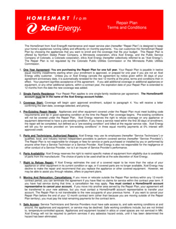
PowerDrive Repair ManualCorded Foot Pedal Test Procedure3- 404/03/03
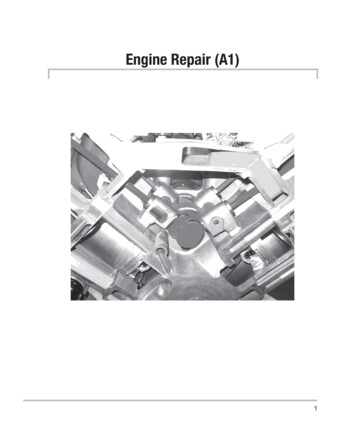
PowerDrive Repair Manual10/31/02Wiring Gauge ChartThe chart below should clarify voltage loss on all of the common wire sizes that wework with. The number represents voltage loss per foot. In calculating loss, thelength of wire should be doubled and multiplied to the number in the chart.AWG5 Amps10 Amps20 Amps30 Amps40 Amps50 Amps4681012.0012 volts.002 volts.0032 volts.0051 volts.0081 volts.0025 volts.004 volts.0064 volts.0102 volts.0162 volts.005 volts.008 volts.0128 volts.0204 volts.0162 volts.0075 volts.012 volts.0192 volts.0306 volts.0486 volts.01 volts.016 volts.0256 volts.0408 volts.0648 volts.0125 volts.02 volts.032 volts.051 volts.081 volts20 foot of 10 gauge wire at 40 amps (40) x (.0408) 1.63 volt drop3- 5
AutoPilot Repair Manual05/14/03Section 4.AutoPilot (PD/AP) Models(Corded foot pedal models, non-Genesis)This AutoPilot Repair Manual (Section 4) is divided into Part I and Part II.Part I pertains to motors manufactured prior to model year 2001 (prior to S/N MKABxxx).(AutoPilot switch is located on the lower speed control cover.)pages 4-1 through 4-7Part II pertains to 2001 and later models (S/N MKABxxx and later).(AutoPilot switch is located on the top control box cover.)pages 4-8 through 4-13PART I.Motors manufactured prior to model year 2001 (prior to S/N MKABxxx).PART I - Case I. Drive Housing will not steer in either direction (in manualmode).Step 1. Check to ensure proper voltage and polarity at battery. Inspect all battery connections, trolling motor plug (ifinstalled), and any butt splice connections in battery leadwire for corrosion and security. Visually check to seethat all wires are attached to proper control board terminals. Consult the appropriate wiring diagram for themodel and board being tested. Clean / rewire, if necessary.Step 2. Check motor with known good test foot pedal or test the original pedal by performing Foot Pedal PCB TestProcedure on page 3-4.A.If test pedal properly steers motor or if the original pedal tests faulty as outlined on page 3-4, theoriginal foot pedal is defective. Disassemble defective pedal to inspect if actuators are properlymaking contact on foot pedal board. Visually inspect foot pedal board for collapsed or burnt domeswitches. Replace foot pedal, if necessary.B.If test pedal does not properly steer motor or if the original pedal tests okay as outlined on page 3-4,then test steering output of main control board. Use a test light (or V.O.M. probes) connected to themain control steering output terminals (consult appropriate wiring diagram). Connect known goodfoot pedal to main control board. Connect battery leads to proper voltage. If there is no board steeringoutput as you try to steer left or right, then the main control board is defective and needs to bereplaced.C.If main PCB has output voltage, drive housing is faulty. Test drive housing by connecting 12-voltpower source directly to drive housing leads. If drive housing does not steer, open drive housing andinspect servo motor, drive gears, and sleeve bushings, for binding/lack of lubrication or water damage.Repair or replace the drive housing, as necessary.PART I - Case II. Drive Housing steers in one direction only (AutoPilot ormanual mode).Step 1. Test drive housing by applying 12 volts to drive housing leads. Reverse polarity to verify drive housing doessteer in both directions.Step 2. Check for a short between either of the drive housing wires and the metal portion of the drive housing itself. Todo this, use a V.O.M. to check for continuity between the drive housing lead and a screw on the underside of thedrive housing.A.If a short is found, disassemble the drive housing and insulate the wire terminals at the drive housing’sservo motor to correct the shorted condition. Reassemble the drive housing and again check for shorts.B.If no shorts are found, proceed to Step 3.Step 3. The steering logic portion of the main control board is faulty. Replace main control board.4- 1
AutoPilot Repair Manual05/14/03PART I - Case III. Drive Housing steers with foot pedal, but will not steer inAutoPilot mode.Step 1. Check continuity of brown, yellow, blue, orange, and white wires in the coil cord with the coil cord stretchedout to length. If you find a break in continuity in any of these wires, the coil cord is defective. Replace coilcord, if required.Step 2. If no break in the continuity of the coil cord, perform the Control Board /Compass Isolation Test following theprocedure provided with the AutoPilot Test Board - Minn Kota P/N 20 (see page 4-4).A.If above test indicates sensor board compass assembly is defective, the replace compass assembly.B.If above test indicates main control board is defective, check functionality of AutoPilot ON/OFFswitch (check for continuity through switch when ON and no continuity with switch OFF). ReplaceON/OFF switch if defective, otherwise replace main control board.PART I - Case IV. AutoPilot changes directions with speed changes.Step 1. Small direction changes with speed changes are normal.Step 2. If direction changes are more than 4 to 5 degrees, perform the Compass Calibration Procedure (see page 4-5).PART I - Case V. Motor won’t steer or steers slowly at higher thrust settings.Step 1. Inspect all battery connections, trolling motor plug (if installed), and any butt splice connections in the batteryleadwire for corrosion and security.Step 2. Check to insure that wire of adequate gauge has been used in the boat’s trolling motor circuit. (Wiring ofinadequate gauge will result in a voltage drop to the motor and steering circuit at higher thrust settings. SeeWiring Gauge chart for recommended minimum wire sizes by amp draw and wire length, page 3-4). If, afterinsuring that all wiring and connections are good, the steering is still slow at high thrust settings, proceed toStep 3.Step 3. Disassemble motor to separate the drive housing from the motor and tube and bowplate/extrusion assembly.A.Remove the six screws holding the top and bottom halves of the drive housing together. (Note: thetop and bottom halves of the drive housing are “pinned” together at the corners with roll pins. The twohalves will need to be pried apart.)B.Inspect the drive housing motor, paying special attention to the drive housing motor armature shaft andmotor bushings. Test run to verify proper high speed operation and RPM.C.Remove the drive housing sleeve and bushings. Thoroughly clean the bushing and sleeve contactsurfaces of all residue and old lubricant. Re-lubricate the bushing and sleeve contact surfaces withSchaeffer’s #238 Moly Ultra Supreme grease or a similar lubricant. Reassemble the drive housingtaking special care to properly realign the drive housing pins, shafts, motor, and gears. Prior toinstalling and tightening the six drive housing case screws, test run the drive housing by applying 12volts directly to the drive housing wire leads. If the drive housing motor runs properly, then make surethere are no gaps between the case halves (a rubber mallet works well to seat the case halvesflush/tight). Install and tighten case screws.D.Reassemble the drive housing to the bow plate/extrusion assembly. Slide the motor and tube throughthe drive housing. Reconnect all wires in the control box and recalibrate AutoPilot compass (see page4-5). Test for proper operation.PART I - Case VI. AutoPilot function is erratic and doesn’t maintain a heading.Step 1. Make sure motor is mounted within 5 degrees of level and there is no ferrous metal object(s) near the motor thatmay be affecting the compass (including screws and/or nuts).Step 2. Check motor for excessive vibration. Inspect propeller and propeller shaft for damage. (Excessive vibrationcan cause the AutoPilot compass to oscillate causing erratic operation.)Step 3. Check for proper voltage to motor while motor is under load. AutoPilot steering is susceptible to erraticoperation in low voltage situations. (Use of adequate wire gauge in boat or any leadwire extension is critical toavoid voltage drop / low voltage to the motor; as can an inadequate or corroded plug / plug receptacle.)4- 2
AutoPilot Repair Manual05/14/03Step 4. Check continuity of brown, yellow, blue, orange, and white wires in the coil cord with the coil cord stretchedout to length. If you find a break in continuity in any of these wires, the coil cord is defective. Replace coilcord, if required.Step 5. Check AutoPilot compass control board for proper voltage levels at the optical sensor circuit. (See Minn KotaService Repair Bulletin #SB122099, AutoPilot Compass Control Board Trim Pot Adjustment Procedure – page4-6.)Step 6. Perform the Control Board / Compass Isolation Test following the procedure provided with the AutoPilot TestBoard – Minn Kota P/N 20 (see page 4-4). If operation is restored replace the sensor board compass assembly.If it isn’t restored, replace the main control board.PART I - Case VII. Motor (lower unit) fails to run or runs intermittently.Step 1. Check for proper voltage and polarity. Visually check to see that all wires are attached to proper control boardterminals. Consult appropriate wiring diagram for the model and board being tested. Check for corrodedconnections. Clean/rewire properly, if necessary.Step 2. Check motor with known good test foot pedal or test the foot pedal by performing the Foot Pedal TestProcedure found on page 3-4.A.If test pedal properly controls all motor functions or if the original foot pedal tests bad as outlined onpage 3-4, the original foot pedal is faulty. Replace foot pedal.B.If motor lower unit does not run properly with test pedal or if the original pedal tests
Hand-Control w/Control Board Repair Manual 01/20/04 2- 2 necessary, solder on replace soft-pot (P/N 2364005) and test motor for proper operation (per the procedure shown in Service Bulletin dated 1/12/99).