Transcription
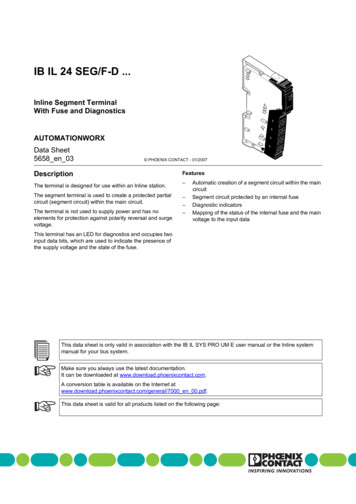
IB IL 24 SEG/F-D .DEInline Segment TerminalWith Fuse and Diagnostics-DG/FSEAUTOMATIONWORXData Sheet5658 en 03 PHOENIX CONTACT - 01/2007DescriptionThe terminal is designed for use within an Inline station.The segment terminal is used to create a protected partialcircuit (segment circuit) within the main circuit.The terminal is not used to supply power and has noelements for protection against polarity reversal and surgevoltage.Features––––Automatic creation of a segment circuit within the maincircuitSegment circuit protected by an internal fuseDiagnostic indicatorsMapping of the status of the internal fuse and the mainvoltage to the input dataThis terminal has an LED for diagnostics and occupies twoinput data bits, which are used to indicate the presence ofthe supply voltage and the state of the fuse.This data sheet is only valid in association with the IB IL SYS PRO UM E user manual or the Inline systemmanual for your bus system.Make sure you always use the latest documentation.It can be downloaded at www.download.phoenixcontact.com.A conversion table is available on the Internet atwww.download.phoenixcontact.com/general/7000 en 00.pdf.This data sheet is valid for all products listed on the following page:
IB IL 24 SEG/F-D .Ordering DataProductsDescriptionTypeOrder No.Pcs./Pck.Inline Segment terminal with fuse and diagnostics; without accessoriestransmission speed of 500 kbpsIB IL 24 SEG/F-D28366831Inline Segment terminal with fuse and diagnostics;complete with accessories (connector and labeling field);transmission speed of 500 kbpsIB IL 24 SEG/F-D-PAC28619041Inline Segment terminal with fuse and diagnostics; without accessoriestransmission speed of 2 MbpsIB IL 24 SEG/F-D-2MBD28550331Inline Segment terminal with fuse and diagnostics;complete with accessories (connector and labeling field);transmission speed of 2 MbpsIB IL 24 SEG/F-D-2MBD-PAC28619461One of the connectors listed below is needed for the complete fitting of the IB IL 24 SEG/F-D and IB IL 24 SEG/F-D-2MBD terminals.AccessoriesDescriptionTypeOrder No.Connector (black, w/o color print)IB IL SCN-PWR IN272746210Connector (black, with color print)IB IL SCN-PWR IN-CP272763710FuseSI 5 x20 6,300 A r No.Pcs./Pkt"Configuring and Installing the INTERBUS Inline Product Range"user manualIB IL SYS PRO UM E27430481"Automation Terminals of the Inline Product Range" user manualIL SYS INST UM E26987371Technical DataGeneral DataHousing dimensions (width x height x depth)12.2 mm x 120 mm x 71.5 mmWeight44 g, approximately (without connector), 59 g, approximately (with connector)Operating modeProcess data mode with 2 bitsAmbient temperature (operation)-25 C to 55 CAmbient temperature (storage/transport)-25 C to 85 CPermissible humidity (operation/storage/transport)10% to 95%, according to DIN EN 61131-2Air pressure (operation/storage/transport)70 kPa to 106 kPa (up to 3000 m above sea level)Degree of protectionIP20 according to IEC 60529Protection classClass 3 according to VDE 0106, IEC 60536Connection data for Inline connectorConnection methodSpring-cage terminalsConductor cross section0.2 mm2 to 1.5 mm2 (solid or stranded), 24 - 16 AWGInterfaceLocal bus5658 en 03Through data routingPHOENIX CONTACT2
IB IL 24 SEG/F-D .Transmission SpeedIB IL 24 SEG/F-D500 kbpsIB IL 24 SEG/F-D-PAC500 kbpsIB IL 24 SEG/F-D-2MBD2 MbpsIB IL 24 SEG/F-D-2MBD-PAC2 MbpsPower Consumption500 kbpsCommunications power UL7.5 V DC7.5 V DCCurrent consumption at UL25 mA, maximum45 mA, maximum2 MbpsPower consumption at UL0.19 W, maximum0.34 W, maximumMain voltage UM24 V DC (nominal value)24 V DC (nominal value)Nominal current consumption at UM4.0 A (nominal value)4.0 A (nominal value)Supply of the Module Electronics and the I/O Through the Bus Coupler/Power Terminal (UL, UM)Connection methodThrough potential routing24 V I/O Supply (UM, US)The main voltage UM is supplied at the bus coupler or at a power terminal. The segment voltage US is provided automatically at this segment terminal andprotected by the internal fuse.Connections for a supply voltage are not provided on the segment terminal. The terminal points are only provided for measuring purposes.Permissible Total Current in the Potential Jumpers ofthe Main and Segment Circuit/Nominal Current of theTerminal500 kbps2 MbpsPermissible total current in the potential jumpers6.3 A5.4 ANominal current of the terminal4.0 A4.0 ATolerance 10% 10%The terminal is supplied with a 6.3 A slow-blow fuse.Power DissipationFormula to Calculate the Power Dissipation of theElectronics (500 kbps)Formula to Calculate the Power Dissipation of theElectronics (2 Mbps)PTOT 0.180 W IL2 x RFPTOT 0.34 W IL2 x RFWhereWherePTOTTotal power dissipation in the terminalPTOTTotal power dissipation in the terminalILLoad current in the segment circuitILLoad current in the segment circuitRFResistance of the fuseRFResistance of the fuseThe resistance of the fuse RF for a 6.3 AT fuse is approximately 12 mΩ.The resistance of the fuse RF for a 6.3 AT fuse is approximately 12 mΩ.The power dissipation of the electronics for a theoretical maximum current of6.3 A (nominal current 4.0 A) is calculated as follows:The power dissipation of the electronics for a theoretical maximum current of5.4 A (nominal current 4.0 A) is calculated as follows:PTOT 0.18 W 39.69 A2 x 0.012 Ω 0.66 WPTOT 0.34 W 29.16 A2 x 0.012 Ω 0.68 WPower Dissipation of the Housing (PHOU) (500 kbps and 2 Mbps)PHOU 0.7 W in the total permissible ambient temperature range5658 en 03PHOENIX CONTACT3
IB IL 24 SEG/F-D .Typical Power Dissipation of the Electronics Depending on the Load Current in the Segment Circuit500 kbps2 Mbps1.10 .91.00.90.80 .60.,7PTOT [W]0 .80 .70 .50 .4PT O T[W ]1.21 .00 .30.60.50.40.30 .20.20 .10.100 .10 .5124IL [A ]6800.10.515 5 6 9 C 0 0 6246IL [A]P [W] Power dissipation in WIL [A] Load current in the segment circuit in AP [W] Power dissipation in WIL [A] Load current in the segment circuit in AThis test was carried out with a 6.3 AT fuse.This test was carried out with a 6.3 AT fuse.86772A006Derating of the Load Current in the Segment CircuitNo deratingSafeguardsOverload/short circuit in the segment circuitFuse 5 x 20 with 6.3 A slow-blowFuses with other values can also be used. The maximum fuse value must not exceed 6.3 A.Note for the selection of fuses:For fuses with a value greater than 2 A, only slow-blow fuses may be used.Surge voltageProtective elements in the power terminal or the bus couplerProtection against polarity reversalProtective elements in the power terminal or the bus couplerElectrical Isolation/Isolation of the Voltage AreasTo provide electrical isolation between the logic level and the I/O area, it is necessary to supply these areas via the bus coupler or via thebus coupler and a power terminal from separate power supply units. Interconnection of the power supply units in the 24 V area is notpermitted. Please also observe the GND/PE connections on the power supply units (see also user manual).Common PotentialsThe 24 V main voltage, 24 V segment voltage, and GND have the same potential. FE is a separate potential area.Separate Potentials in the System Consisting of Bus Coupler/Power Terminal and I/O Terminal- Test Distance- Test Voltage5 V supply incoming remote bus/7.5 V supply (bus logic)500 V AC, 50 Hz, 1 min.5 V supply outgoing remote bus/7.5 V supply (bus logic)500 V AC, 50 Hz, 1 min.7.5 V supply (bus logic)/24 V supply (I/O)500 V AC, 50 Hz, 1 min.24 V supply (I/O)/functional earth ground500 V AC, 50 Hz, 1 min.Error Messages to the Higher-Level Control or Computer SystemI/O error message if fuse has blown or is missingI/O error message if supply voltage UM is not presentApprovalsFor the latest approvals, please visit www.download.phoenixcontact.com.5658 en 03PHOENIX CONTACT4
IB IL 24 SEG/F-D .Local Diagnostic and Status Indicatorsand Terminal Point AssignmentDESEG/F-DLocal Diagnostic IndicatorsDes. ColorDGreenON:Flashing:0.5 Hz:2 Hz:DESEG/F-D4 eaningDiagnosticsBus activeCommunications power present, Busnot activeCommunications power present,supply voltage UM not present or fusehas blown.Communications power present,local bus errorCommunications power not present,Bus not activeFuse in segment circuit USFuse OKFuse has blownIf supply voltage UM is not present and the fusehas blown or is missing, an I/O error messageis generated on the higher-level control orcomputer system.2.45658B003Figure 1A blown or missing fuse is indicated by bothdiagnostic indicators. The red E LED lights upand the green D LED flashes at 2 Hz.Terminal with appropriate connectorFunction IdentificationBlack2 Mbps: white stripe in the vicinity of the LED DTerminal Point AssignmentTerminalPoint1.1, 2.11.2, 2.21.3, 2.31.4, 2.4AssignmentSegment voltage US(after the fuse)Main voltage UMGND of the supply voltagesFunctional earth ground (FE)The terminal points are only provided formeasuring purposes.5658 en 03PHOENIX CONTACT5
IB IL 24 SEG/F-D .Internal Circuit DiagramProgramming DataLocal Bus (INTERBUS)Local busOPCDULEID codeBEhex (190dec)Length codeC2hexProcess data channel2 bitsInput address area2 bitsOutput address area0 bitsParameter channel (PCP)0 bitsRegister length (bus)2 bitsOther Bus SystemsFor the programming data/configuration dataof other bus systems, please refer to thecorresponding electronic device data sheet(e.g., GSD, EDS). 24 V (US) 24 V (UM) 24 V (UM)Process DataAssignment of IN Process Data7383A004Figure 2Internal wiring of the terminal pointsKey:OPCProtocol chip(bus logic including voltage conditioning)LED with details of the indicator designation"D" or "E" (see page 5)OptocouplerFuseCapacitive connection to functional earthground (FE)The IN process data only maps the status ofthe fuse and the main voltage.(Byte.bit) viewAssignment Main voltage UM present,fuse OKMain voltage UM present,fuse blown or missingMain voltage UM not present0.1 0.0111000For the assignment of the illustrated (byte.bit) view to your INTERBUS control or computersystem, please refer to theDB GB IBS SYS ADDRESS data sheet, OrderNo. 9000990.Electrically isolated area PHOENIX CONTACT 01/2007Other symbols used are explained in theIB IL SYS PRO UM E user manual or thesystem manual for your bus system.5658 en 03PHOENIX CONTACT GmbH & Co. KG 32823 Blomberg GermanyPhone: 49-(0) 5235-3-00 Fax: 49-(0) 5235-3-4 12 00www.phoenixcontact.com6
IB IL 24 SEG/F-D-2MBD-PAC 2861946 1 One of the connectors listed below is needed for the complete fitting of the IB IL 24 SEG/F-D and IB IL 24 SEG/F-D-2MBD termina ls. Accessories Description Type Order No. Pcs./Pkt Connector (black, w/o color print) IB IL SCN-PWR IN 2727462 10 Connector (black, with color print) IB IL SCN-PWR IN-CP 2727637 10