Transcription
GKS9GAS-FIRED WARM AIR FURNACEINSTALLATION INSTRUCTIONSThis furnace is shipped from the factory as a Dedicated Upflow. A “Blocked Drain Kit” is available and MUSTBE USED if the furnace is installed Horizontal Left or Horizontal Right. Check the Serial/Rating Plate on thefurnace for the Kit part number.Installer: Affix all manuals adjacent to the unit.(Type FSP CATEGORY IV Direct or Non Direct Vent Air Furnace)These furnaces comply with requirementsembodied in the American National Standard/ National Standard of Canada ANSIZ21.47·CSA-2.3 Gas Fired Central Furnaces. CUSRECOGNIZE THIS SYMBOL AS A SAFETY PRECAUTION.ATTENTION INSTALLING PERSONNELAs a professional installer you have an obligation to know the product better than the customer. This includes all safetyprecautions and related items.Prior to actual installation, thoroughly familiarize yourself with this Instruction Manual. Pay special attention to all safetywarnings. Often during installation or repair it is possible to place yourself in a position which is more hazardous thanwhen the unit is in operation.Remember, it is your responsibility to install the product safely and to know it well enough to be able to instruct acustomer in its safe use.Safety is a matter of common sense.a matter of thinking before acting. Most dealers have a list of specific good safetypractices.follow them.The precautions listed in this Installation Manual are intended as supplemental to existing practices. However, if there isa direct conflict between existing practices and the content of this manual, the precautions listed here take precedence.*NOTE: Please contact your distributor or ourwebsite for the applicable Specification Sheetreferred to in this manual.IO-300DGoodman Manufacturing Company, L.P.5151 San Felipe, Suite 500, Houston, TX 77056www.goodmanmfg.com 2006-2007 Goodman Manufacturing Company, L.P.8/07
Table of ContentsI. Component Identification . 5II. Safety . 6ELECTROSTATIC DISCHARGE (ESD) PRECAUTIONS . 6III. Product Application . 6IV. Location Requirements & Considerations . 7GENERAL . 7CLEARANCES AND ACCESSIBILITY . 8FURNACE SUSPENSION . 8EXISTING FURNACE REMOVAL . 8THERMOSTAT LOCATION . 9V. Combustion & Ventilation Air Requirements . 9VI. Installation Positions . 11VII. Horizontal Applications & Considerations . 11GENERAL .11DRAIN TRAP AND LINES .11LEVELING .11ALTERNATE VENT/FLUE CONNECTION .11ALTERNATE ELECTRICAL AND GAS LINE CONNECTIONS . 12DRAIN PAN . 12FREEZE PROTECTION . 12FURNACE SUSPENSION . 12VIII. Propane Gas /High Altitude Installations . 12IX. Vent/Flue Pipe & Combustion Air Pipe . 12GENERAL . 12DUAL CERTIFICATION: NON-DIRECT/DIRECT VENT . 12MATERIALS AND JOINING METHODS . 13PROPER VENT/FLUE AND COMBUSTION AIR PIPING PRACTICES . 13TERMINATION LOCATIONS . 13CANADIAN VENTING REQUIREMENTS . 13STANDARD FURNACE CONNECTIONS . 14ALTERNATE FURNACE CONNECTIONS . 14NON-DIRECT VENT (SINGLE PIPE) PIPING . 15DIRECT VENT (DUAL PIPE) PIPING . 16VENT/INTAKE TERMINATIONS FOR INSTALLATION OF MULTIPLE DIRECT VENT FURNACES . 17CONCENTRIC VENT TERMINATION . 18SIDE WALL VENT KIT . 18X. Condensate Drain Lines & Drain Trap . 18GENERAL . 18UPRIGHT INSTALLATIONS . 18HORIZONTAL INSTALLATIONS . 19XI. Electrical Connections . 20WIRING HARNESS . 21115 VOLT LINE CONNECTIONS . 2124 VOLT THERMOSTAT WIRING . 21XII. Gas Supply and Piping . 21GENERAL . 21GAS PIPING CONNECTIONS . 22PROPANE GAS TANKS AND PIPING . 24XIII. Circulating Air & Filters . 24DUCTWORK - AIR FLOW . 24BOTTOM RETURN AIR OPENING [UPFLOW MODELS] . 25FILTERS - READ THIS SECTION BEFORE INSTALLING THE RETURN AIR DUCTWORK . 25UPRIGHT INSTALLATIONS . 25HORIZONTAL INSTALLATIONS . 262
Table of ContentsXIV. Startup Procedure & Adjustment . 26HEAT ANTICIPATOR SETTING . 26DRAIN TRAP PRIMING . 26FURNACE OPERATION . 26GAS SUPPLY PRESSURE MEASUREMENT . 26GAS MANIFOLD PRESSURE MEASUREMENT AND ADJUSTMENT . 27GAS INPUT RATE MEASUREMENT (NATURAL GAS ONLY) . 27TEMPERATURE RISE . 27CIRCULATOR BLOWER SPEEDS . 28XV. Normal Sequence of Operation . 28POWER UP .HEATING MODE .COOLING MODE .FAN ONLY MODE .28282828XVI. Operational Checks . 28BURNER FLAME . 28XVII. Safety Circuit Description . 29GENERAL . 29INTEGRATED CONTROL MODULE . 29PRIMARY LIMIT . 29AUXILIARY LIMIT . 29ROLLOUT LIMIT . 29PRESSURE SWITCHES . 29FLAME SENSOR . 29XVIII. Troubleshooting . 29ELECTROSTATIC DISCHARGE (ESD) PRECAUTIONS . 29DIAGNOSTIC CHART . 29RESETTING FROM LOCKOUT . 29XIX. Maintenance . 30ANNUAL INSPECTION . 30FILTERS . 30BURNERS . 30INDUCED DRAFT AND CIRCULATOR BLOWERS . 30CONDENSATE TRAP AND DRAIN SYSTEM (QUALIFIED SERVICER ONLY) . 30FLAME SENSOR (QUALIFIED SERVICER ONLY) . 30IGNITER (QUALIFIED SERVICER ONLY) . 30FLUE PASSAGES (QUALIFIED SERVICER ONLY) . 30XX. Internal Filter Removal . 31XXI. Before Leaving an Installation . 31XXII. Repair & Replacement Parts . 31APPENDIXTroubleshooting Chart . 33GKS9 Wiring Diagram . 34WARNINGGOODMAN WILL NOT BE RESPONSIBLE FOR ANY INJURY ORPROPERTY DAMAGE ARISING FROM IMPROPER SERVICE OR SERVICEPROCEDURES. IF YOU INSTALL OR PERFORM SERVICE ON THIS UNIT,YOU ASSUME RESPONSIBILITY FOR ANY PERSONAL INJURY ORPROPERTY DAMAGE WHICH MAY RESULT. MANY JURISDICTIONSREQUIRE A LICENSE TO INSTALL OR SERVICE HEATING AND AIRCONDITIONING EQUIPMENT.3
TO THE INSTALLERWARNINGBefore installing this unit, please read this manual thoroughly tofamiliarize yourself with specific items which must be adhered to,including but not limited to: unit maximum external static pressure,gas pressures, BTU input rating, proper electrical connections, circulating air temperature rise, minimum or maximum CFM, and motor speed connections.IFTHE INFORMATION IN THESE INSTRUCTIONS IS NOT FOLLOWEDEXACTLY, A FIRE OR EXPLOSION MAY RESULT CAUSING PROPERTYDAMAGE, PERSONAL INJURY OR LOSS OF LIFE.- DO NOT STORE OR USE GASOLINE OR OTHER FLAMMABLE VAPORSAND LIQUIDS IN THE VICINITY OF THIS OR ANY OTHER APPLIANCE.- WHAT TO DO IF YOU SMELL GAS:* DO NOT TRY TO LIGHT ANY APPLIANCE.* DO NOT TOUCH ANY ELECTRICAL SWITCH; DO NOT USEANY PHONE IN YOUR BUILDING.* IMMEDIATELY CALL YOUR GAS SUPPLIER FROM ANEIGHBORS PHONE. FOLLOW THE GAS SUPPLIERSINSTRUCTIONS.* IF YOU CANNOT READCH YOUR GAS SUPPLIER, CALL THEFIRE DEPARTMENT.- INSTALLATION AND SERVICE MUST BE PERFORMED BY A QUALIFIEDINSTALLER, SERVICE AGENCY OR THE GAS SUPPLIERTRANSPORTATION DAMAGEAll units are securely packed in shipping containers tested according to International Safe Transit Association specifications. The carton must be checked upon arrival for external damage. If damageis found, a request for inspection by carrier’s agent must be made inwriting immediately.The furnace must be carefully inspected on arrival for damage andbolts or screws which may have come loose in transit. In the eventof damage the consignee should:1. Make a notation on delivery receipt of any visible damage toshipment or container.2. Notify carrier promptly and request an inspection.3. With concealed damage, carrier must be notified as soon aspossible - preferably within five days.4. File the claim with the following support documents within anine month statute of limitations.WARNINGSHOULD OVERHEATING OCCUR OR THE GAS SUPPLY FAIL TO SHUTOFF, TURN OFF THE MANUAL GAS SHUTOFF VALVE EXTERNAL TO THEFURNACE BEFORE TURNING OFF THE ELECTRICAL SUPPLY. Original or certified copy of the Bill of Lading, or indemnitybond. Original paid freight bill or indemnity in lieu thereof.Original or certified copy of the invoice, showing trade andother discounts or reductions. Copy of the inspection report issued by carrier ’srepresentative at the time damage is reported to carrier.The carrier is responsible for making prompt inspection of damageand for a thorough investigation of each claim. The distributor ormanufacturer will not accept claims from dealers for transportationdamage.CARBON MONOXIDE POISONING HAZARDKeep this literature in a safe place for future reference.Special Warning for Installation of Furnace or Air Handling Units inEnclosed Areas such as Garages, Utility Rooms or Parking AreasCarbon monoxide producing devices (such as an automobile, spaceheater, gas water heater, etc.) should not be operated in enclosed areassuch as unventilated garages, utility rooms or parking areas because ofthe danger of carbon monoxide (CO) poisoning resulting from the exhaustemissions. If a furnace or air handler is installed in an enclosed area suchas a garage, utility room or parking area and a carbon monoxide producingdevice is operated therein, there must be adequate, direct outsideventilation.This ventilation is necessary to avoid the danger of CO poisoning whichcan occur if a carbon monoxide producing device continues to operate inthe enclosed area. Carbon monoxide emissions can be (re)circulatedthroughout the structure if the furnace or air handler is operating in anymode.CO can cause serious illness including permanent brain damage or death.B10259-2164
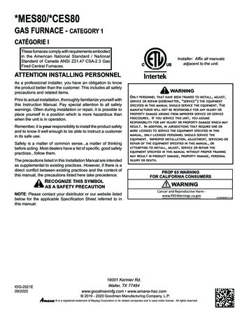
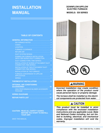
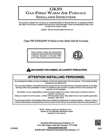
I.BURNER 132141152717291826BLOWER 3456789101112131415Gas ValveGas Line Entrance (Alternate)Combustion Air Intake Connection / “Coupling”Hot Surface IgniterBurnersRollout LimitFlame SensorFlue Pipe Connection / “Coupling”Flue Pipe (Internal)Primary LimitPressure SwitchGas Line EntranceRubber ElbowFlue Pipe Connection (Alternate)Induced Draft Blower16171819202122232425262728295Electrical Connection Inlets (Alternate)Coil Front Cover Drain PortDrain Line PenetrationsBlower Door Interlock Switch24-Volt Thermostat ConnectionsIntegrated Control Module(with fuse and diagnostic LED)Transformer (40 VA)Circulator BlowerAuxiliary LimitGas ManifoldJunction BoxCoil Front CoverDrain TrapElectrical Connection Inlets
If you come in contact with an ungrounded object, repeatstep 2 before touching control or wires.4. Discharge your body to ground before removing a newcontrol from its container. Follow steps 1 through 3 ifinstalling the control on a furnace. Return any old or newcontrols to their containers before touching any ungroundedobject.II. SAFETYPlease adhere to the following warnings and cautions when installing, adjusting, altering, servicing, or operating the furnace.WARNINGTO PREVENT PERSONAL INJURY OR DEATH DUE TO IMPROPERINSTALLATION , ADJUSTMENT, ALTERATION, SERVICE ORMAINTENANCE, REFER TO THIS MANUAL. FOR ADDITIONALASSISTANCE OR INFORMATION, CONSULT A QUALIFIED INSTALLER,SERVICE AGENCY OR THE GAS SUPPLIER.III. PRODUCT APPLICATIONThis furnace is primarily designed for residential home-heatingapplications. It is NOT designed or certified for use in mobilehomes, trailers or recreational vehicles. This unit is NOT designedor certified for outdoor applications. The furnace must be installedindoors (i.e., attic space, crawl space, or garage area provided thegarage area is enclosed with an operating door).This furnace can be used in the following non-industrial commercial applications:Schools, Office buildings, Churches, Retail storesNursing homes, Hotels/motels, Common or office areasIn such applications , the furnace must be installed with the following stipulations: It must be installed per the installation instructionsprovided and per local and national codes. It must be installed indoors in a building constructed onsite. It must be part of a ducted system and not used in a freeair delivery application. It must not be used as a “make-up” air unit. It must be installed with two-pipe systems for combustionair, especially if VOC’s or other contaminants are presentin the conditioned space. All other warranty exclusions and restrictions apply Thisfurnace is an ETL dual-certified appliance and isappropriate for use with natural or propane gas (NOTE: Ifusing propane, a propane conversion kit is required).Dual certification means that the combustion air inlet pipe is optional and the furnace can be vented as a:Non-direct vent (single pipe) central forced air furnace inwhich combustion air is taken from the installation areaor from air ducted from the outside or,Direct vent (dual pipe) central forced air furnace in whichall combustion air supplied directly to the furnace burnersthrough a special air intake system outlined in theseinstructions.This furnace may be used as a construction site heater ONLY if thefollowing conditions are met: The vent system is permanently installed per theseinstallation instructions. A room thermostat is used to control the furnace. Fixedjumpers that provide continuous heating CANNOT beused. Return air ducts are provided and sealed to the furnace. A return air temperature range between 60ºF (16ºC) and80ºF (27ºC) is maintained. Air filters are installed in the system and maintainedduring construction, replaced as appropriate duringconstruction, and upon completion of construction arereplaced. The input rate and temperature rise are set per the furnacerating plate. 100% outside air is provided for combustion airrequirements during construction. Temporary ducting canbe used.THIS PRODUCT CONTAINS OR PRODUCES A CHEMICAL OR CHEMICALSWHICH MAY CAUSE SERIOUS ILLNESS OR DEATH AND WHICH AREKNOWN TO THE STATE OF CALIFORNIA TO CAUSE CANCER, BIRTHDEFECTS OR OTHER REPRODUCTIVE HARM.WARNINGHIGH VOLTAGE!TO AVOID PROPERTY DAMAGE, PERSONAL INJURY ORDEATH DUE TO ELECTRICAL SHOCK , THE FURNACE MUSTBE LOCATED TO PROTECT THE ELECTRICALCOMPONENTS FROM WATER.WARNINGDO NOT UTILIZE THE HEATING UNIT WITHOUT REASONABLE ROUTINEINSPECTION, MAINTENANCE AND SUPERVISION. IF THE UNIT IS IN ABUILDING THAT IS OR WILL BE VACANT, CARE SHOULD BE TAKEN TOROUTINELY INSPECT , MAINTAIN AND MONITOR THE UNIT. IN THEEVENT THAT THE BUILDING MAY BE EXPOSED TO FREEZINGTEMPERATURES AND WILL BE VACANT, DRAIN ALL WATER-BEARINGPIPES, PROPERLY WINTERIZE THE BUILDING, AND TURN OFF ALLWATER SOURCES. IN THE EVENT THAT THE BUILDING IS EXPOSED TOFREEZING TEMPERATURES AND IS VACANT, ANY HYDRONIC COILUNITS SHOULD ALSO BE DRAINED AND AN ALTERNATIVE HEATSOURCES UTILIZED.ELECTROSTATIC DISCHARGE (ESD) PRECAUTIONSNOTE: Discharge static electricity accumulated in the body beforetouching the unit. An electrostatic discharge can adversely affectelectrical components.Use the following precautions during furnace installation and servicing to protect the integrated control module from damage. Byputting the furnace, the control, and the person at the same electrostatic potential, these steps will help avoid exposing the integratedcontrol module to electrostatic discharge. This procedure is applicable to both installed and non-installed (ungrounded) furnaces.1. Disconnect all power to the furnace. Do not touch theintegrated control module or any wire connected to the controlprior to discharging your body’s electrostatic charge toground.2. Firmly touch a clean, unpainted, metal surface of thefurnaces near the control. Any tools held in a person’shand during grounding will be discharged.3. Service integrated control module or connecting wiringfollowing the discharge process in step 2. Use caution notto recharge your body with static electricity; (i.e., do not moveor shuffle your feet, do not touch ungrounded objects, etc.).6
NOTE: Do not connect the temporary duct directly to thefurnace. The duct must be sized according to theinstructions under Section V, Combustion and VentilationAir Requirements, Section 5.3.3.The furnace heat exchanger, components, duct system,air filters and evaporator coils are thoroughly cleanedfollowing final construction clean up.All furnace operating conditions (including ignition, inputrate, temperature rise and venting) are verified accordingto these installation instructions.dance with “ASHRAE Guide” or “Manual J-Load Calculations” published by the Air Conditioning Contractors of America.IV. LOCATION REQUIREMENTS & CONSIDERATIONSGENERALWARNINGTO PREVENT POSSIBLE EQUIPMENT DAMAGE, PROPERTY DAMAGE,PERSONAL INJURY OR DEATH, THE FOLLOWING BULLET POINTS MUSTBE OBSERVED WHEN INSTALLING THE UNIT.NOTE: The Commonwealth of Massachusetts requires that theFollow the instructions listed below when selecting a furnace locafollowing additional requirements must also be met:tion. Refer also to the guidelines provided in Section V, Combus Gas furnaces must be installed by a licensed plumber ortion and Ventilation Air Requirements.gas fitter. Centrally locate the furnace with respect to the proposed A T-handle gas cock must be used.or existing air distribution system. If the unit is to be installed in an attic, the passageway to Ensure the temperature of the return air entering theand the service area around the unit must have flooring.furnace is between 55 F and 100 F when the furnace isheating.To ensure proper installation and operation, thoroughly read thismanual for specifics pertaining to the installation and application Provide provisions for venting combustion productsof this product.outdoors through a proper venting system. Specialconsideration should be given to vent/flue pipe routingand combustion air intake pipe when applicable. ReferWARNINGto Section IX, Vent/Flue Pipe and Combustion Air Pipe Termination Locations for appropriate terminationPOSSIBLE PROPERTY DAMAGE, PERSONAL INJURY OR DEATH DUE TOlocations and to determine if the piping system fromFIRE, EXPLOSION, SMOKE, SOOT, CONDENSATION, ELECTRICALfurnace to termination can be accomplished within theSHOCK OR CARBON MONOXIDE MAY RESULT FROM IMPROPERguidelines given. NOTE: The length of flue and/orINSTALLATION , REPAIR, OPERATION, OR MAINTENANCE OF THIScombustion air piping can be a limiting factor in thePRODUCT .location of the furnace. Locate the furnace so condensate flows downwards toWARNINGthe drain. Do not locate the furnace or its condensatedrainage system in any area subject to below freezingTO PREVENT PERSONAL INJURY, PROPERTY DAMAGE OR DEATH DUEtemperatures without proper freeze protection. Refer toTO FIRE, DO NOT INSTALL THIS FURNACE IN A MOBILE HOME,Section X, Co
Goodman Manufacturing Company, L.P. 5151 San Felipe, Suite 500, Houston, TX 77056 www.goodmanmfg.com . The furnace must be carefully inspected on arrival for damage and bolts or screws which may have come loose in transit. In the event of damage the consignee should: 1. Make a notation on delivery receipt of any visible damage to