Transcription
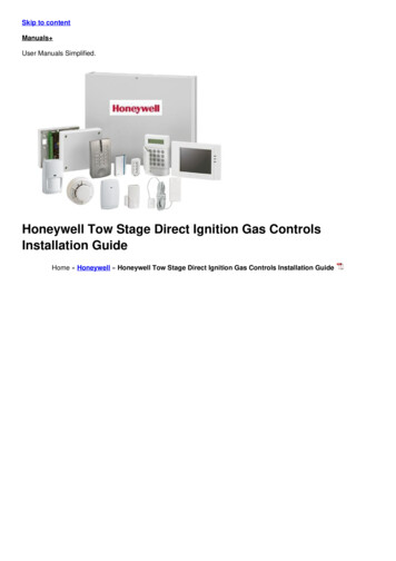
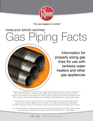
Single Stage High Efficiency Gas Furnaces80 AFUEINSTALLATION INSTRUCTIONS*SA Upflow / Horizontal FurnaceWARNINGFIRE OR EXPLOSION HAZARD Failure to follow safety warnings exactly couldresult in serious injury or property damage. Installation and service must be performedby a qualified installer, service agency or thegas supplier. Do not store or use gasoline or otherflammable vapors and liquids in the vicinityof this or any other appliance.WHAT TO DO IF YOU SMELL GAS Do not try to light any appliance. Do not touch any electrical switch; do notuse any phone in your building. Leave the building immediately. Immediately call your gas supplier from aneighbor’s phone. Follow the gas supplier’sinstructions. If you cannot reach your gas supplier, callthe fire department.*SK Downflow FurnaceAVERTISSEMENTRISQUE D’INCENDIE OU D’ EXPLOSION Le non-respect des avertissements desécurité pourrait entraîner des blessuresgraves, la mort ou des dommages matériels. L’installation et l’entretien doivent êtreeffectués par un installateur qualifié, unorganisme de service ou le fournisseur degazstaller, service agency or the gas supplier. Ne pas entreposer ni utiliser de l’essence nid’autres vapeurs ou liquides inflammablesdans le voisinage de cet appareil, ni de toutautre appareil.QUE FAIRE S’IL Y A UNE ODEUR DE GAZ Ne pas tenter d’allumer aucun appareil. Ne toucher à aucun interrupteur électrique;n’utiliser aucun téléphone dans le bâtiment. Évacuer l’immeuble immédiatement. Appeler immédiatement le fournisseur degaz en employant le téléphone d’un voisin.Respecter à la lettre les instructions dufournisseur de gaz. Si personne ne répond, appeler le service desincendies.DO NOT DESTROY THIS MANUAL. KEEP IN A SAFE PLACE FOR FUTURE REFERENCE.
TABLE OF CONTENTSIMPORTANT SAFETY INFORMATION. 3REQUIREMENTS & CODES. 3Combustion Air Quality. 4Clearances to Combustible Materials. 4Heating Load. 4Installation in a Garage. 5Operation of Furnace During Construction. 5COMBUSTION AIR & VENTING REQUIREMENTS. 6Important Information. 7Installation in a Confined Space. 7Air From Inside. 7Outdoor Air Using a Crawl Space orVented Attic. 7Outdoor Air Using Vertical Ducts. 7Outdoor Air Using Horizontal Ducts. 7Air Directly Through an Exterior Wall . 8Alternate Method of Providing Air fromOutside. 9Installation in an Unconfined Space. 9Category I Venting. 9Horizontal Venting. 10Flexible Vent Systems. 10CIRCULATING AIR REQUIREMENTS. 11Plenums & Air Ducts. 11Return Air Connections. 11Upflow & Horizontal Furnaces. 11Downflow Furnaces. 12Supply Air Connections. 12Acoustical Treatments. 12FURNACE INSTALLATION. 12About the Furnace. 12Before you Install the Furnace. 12Locating the Furnace. 13Upflow Furnaces. 13Horizontal Furnaces. 13Downflow Furnaces. 14Installation on a Concrete Slab. 14Pressure Switches. 15Bottom Panel Removal. 15Alternate Bottom Panel Removal. 15GAS SUPPLY & PIPING. 16Leak Check . 16High-Altitude Application. 17Conversion to LP / Propane. 192ELECTRICAL WIRING. 19Line Voltage Wiring. 19Grounding. 20Thermostat / Low Voltage Connections. 21Heat Anticipator. 21Twinning. 21START-UP & ADJUSTMENTS. 22Pre-Start Checklist. 22Start-Up Procedures. 22Verifying & Adjusting Input Rate. 22Verifying & Adjusting Temperature Rise. 23Verifying Burner Operation. 23Verify Operation of the Supply AirLimit Switch. 23OPERATING SEQUENCE. 23Heating Cycle. 23Cooling Cycle. 23Fan Mode. 24MAINTENANCE. 24FIGURES & TABLES. 26Figure 18 - Furnace Dimensions. 26Airflow Data. 27Table 3 - Upflow / Horizontal Gas Furnaces. 27Table 4 - Downflow Gas Furnaces. 29Electrical Information. 30Figure 19 - Wiring Diagram. 30Gas Information. 31Table 5 - Gas Flow Rates. 31Table 6 - Gas Pipe Capacities. 31Table 7 - High Altitude Deration Chart forPropane Gas. 32Table 8 - Natural Gas Heating Values. 32Table 9 - High Altitude Deration Chart forNat. Gas - High Heating Values. 33Table 10 - High Altitude Deration Chart forNat. Gas - Low Heating Values. 33Troubleshooting. 34Table 11 - Control Board Fault Conditions. 34Furnace Components. 34Figure 20 - Component Locations. 35INSTALLATION / PERFORMANCE CHECKLIST. 36
IMPORTANT SAFETY INFORMATIONINSTALLER: Please read all instructions before servicingthis equipment. Pay attention to all safety warnings andany other special notes highlighted in the manual. Safetymarkings are used frequently throughout this manual todesignate a degree or level of seriousness and shouldnot be ignored.WARNING - indicates a potentially hazardous situationthat if not avoided, could result in personal injury or death.CAUTION - indicates a potentially hazardous situationthat if not avoided, may result in minor or moderate injuryor property damage.WARNING:The safety information listed in this manualmust be followed during the installation,service, and operation of this unit. Unqualifiedindividuals should not attempt to interpret theseinstructions or install this equipment. Failureto follow safety recommendations could resultin possible damage to the equipment, seriouspersonal injury or death. To minimize equipment failure or personal injury, it isessential that only qualified individuals install, service, ormaintain this equipment. If you do not posses mechanicalskills or tools, call your local dealer for assistance. Follow all precautions in the literature, on tags, andon labels provided with the equipment. Read andthoroughly understand the instructions provided withthe equipment prior to performing the installation andoperational checkout of the equipment. Use caution when handling this appliance or removingcomponents. Personal injury can occur from sharp metaledges present in all sheet metal constructed equipment. Do not store any of the following on, or in contact with,the unit: Rags, brooms, vacuum cleaners, or othercleaning tools, spray or aerosol cans, soap powders,bleaches, waxes, cleaning compounds, plastics orplastic containers, paper bags or other paper products,gasoline, kerosene, cigarette lighter fluid, dry cleaningfluids, paint thinners, or other volatile fluids. The installer should become familiar with the units wiringdiagram before making any electrical connections to theunit. See the unit wiring label or Figure 19 (page 30). Always reinstall the doors on the indoor blower afterservicing or cleaning/changing the filters. Do not operatethe indoor blower without all doors and covers in place.Requirements & CodesWARNING:Improper installation, service, adjustment,or maintenance may cause explosion, fire,electrical shock or other hazardous conditionswhich may result in personal injury or propertydamage. Unless otherwise noted in theseinstructions, only factory authorized kits oraccessories may be used with this product.WARNING:Unless otherwise noted in these instructions,only factory authorized kits or accessories maybe used with or when modifying this product.WARNING:Do not install this furnace if any part has beensubmerged under water. A flood damagedfurnace is extremely dangerous. Attempts touse the furnace may result in fire or explosion. Aqualified service agency should be contacted toinspect the furnace and to replace any electricalor control system parts that have been wet orunder water. This furnace must be installed in accordance withthese instructions, all applicable local building codesand the current revision of the National Fuel Gas Code(NFPA54/ANSI Z223.1) or the Natural Gas and PropaneInstallation Code, CAN/CGA B149.1. Use only with type of gas approved for this furnace.Refer to the furnace rating plate. Install this furnace only in a location and position asspecified on page 5. Provide adequate combustion and ventilation air to thefurnace space as specified on pages 6 - 10. Combustion products must be discharged outdoors.Connect this furnace to an approved vent system only,as specified on pages 9 - 10. Never test for gas leaks with an open flame. Usea commercially available soap solution to check allconnections. See pages 16 - 17. This furnace is designed to operate with a maximumexternal pressure rise of 0.5 inches of water column.Consult Tables 3 & 4 (pages 27 - 29), and the ratingplate for the proper circulating air flow and temperaturerise. It is important that the duct system be designed tohandle the desired flow rate and temperature rise. Animproperly designed duct system can result in nuisanceshutdowns, and comfort or noise issues. When supply ducts carry air circulated by the furnaceto areas outside the space containing the furnace, thereturn air shall also be handled by duct(s) sealed tothe furnace casing and terminating outside the spacecontaining the furnace. See pages 11 - 12. This furnace may be used for temporary heating ofbuildings or structures under construction. See theguidelines listed on page 5.3
A gas-fired furnace for installation in a residential garagemust be installed as specified on page 5. This furnace is not approved for installation in mobilehomes. Installing this furnace in a mobile home couldcause fire, property damage, and/or personal injury. If the furnace is installed in a confined space, it isrequired that the necessary combustion air come fromthe outdoors by way of attic, crawl space, air duct, ordirect opening. For Installations in confined spaces, seepages 7 - 9 for combustion air requirements.The information listed below is for reference purposes onlyand does not necessarily have jurisdiction over local or statecodes. Always consult with local authorities before installingany gas appliance. Installations in these locations may require outdoor airfor combustion, due to chemical exposures:Commercial buildingsBuildings with indoor poolsFurnaces installed in laundry roomsFurnaces installed in hobby or craft roomsFurnaces installed near chemical storage areasCombustion & Ventilation Air US: National Fuel Gas Code (NFGC), Air for Combustionand Ventilation CANADA: Natural Gas and Propane Installation Codes(NSCNGPIC), Venting Systems and Air Supply forAppliancesDuct Systems US and CANADA: Air Conditioning Contractors Association(ACCA) Manual D, Sheet Metal and Air ConditioningContractors National Association (SMACNA), or AmericanSociety of Heating, Refrigeration, and Air ConditioningEngineers (ASHRAE) Fundamentals HandbookElectrical Connections US: National Electrical Code (NEC) ANSI/NFPA 70 CANADA: Canadian Electrical Code CSA C22.1Gas Piping & Gas Pipe Pressure Testing US: NFGC and National Plumbing Codes CANADA: NSCNGPICGeneral Installation US: Current edition of the NFGC and the NFPA 90B. Forcopies, contact the National Fire Protection AssociationInc., Batterymarch Park, Quincy, MA 02269; or AmericanGas Association, 400 N. Capitol, N.W., Washington DC20001 or www.NFPA.org CANADA: NSCNGPIC. For a copy, contact Standard Sales,CSA International, 178 Rexdale Boulevard, Etobicoke(Toronto), Ontario, M9W 1R3 CanadaSafety US: (NFGC) NFPA 54–1999/ANSI Z223.1 and theInstallation Standards, Warm Air Heating and AirConditioning Systems ANSI/NFPA 90B. CANADA: CAN/CGA-B149.1 and .2–M00 NationalStandard of Canada. (NSCNGPIC)Combustion Air QualityCAUTION:Combustion air must not be drawn from acorrosive atmosphere.To maximize heat exchanger life, the combustion airmust be free of chemicals that can form corrosive acidiccompounds in the combustion gases. The recommendedsource of combustion air is to use outdoor air. However,the use of indoor air in most applications is acceptableexcept as listed:4 Exposure to the following substances in the combustionair supply may require outdoor air for combustion:Permanent wave solutionsChlorinated waxes and cleanersChlorine based swimming pool chemicalsWater softening chemicalsDe-icing salts or chemicalsCarbon TetrachlorideHalogen type refrigerantsCleaning solvents (perchloroethylene)Printing inks, paint removers, varnishes, etc.Hydrochloric AcidCements and gluesAntistatic fabric softenersMasonry acid washing materialsClearances to Combustible MaterialsThis furnace is Design Certified in the U.S. and Canadaby CSA International for the minimum clearances tocombustible materials. NOTE: The furnace is listed forinstallation on combustible or non-combustible flooring.However, wood is the only combustible flooring allowedfor installation. Downflow models must use the appropriatesubase kit when installing over a wood floor. To obtainmodel number and specific clearance information, referto the furnace rating plate, located inside of the furnacecabinet.Access for positioning and servicing the unit must beconsidered when locating unit. The need to provideclearance for access to panels or doors may requireclearance distances over and above the requirements.Allow 24 inches minimum clearance from the front ofthe unit. However 36 inches is strongly recommended.See Figure 1 (page 5) for minimum clearance requirements.Heating LoadThe furnace should be sized to provide the design heatingload requirement. Heating load estimates can be madeusing approved methods available from Air ConditioningContractors of America (Manual J); American Society ofHeating, Refrigerating, and Air Conditioning Engineers;or other approved engineering methods. Excessiveoversizing of the furnace could cause the furnaceand/or vent to fail prematurely.
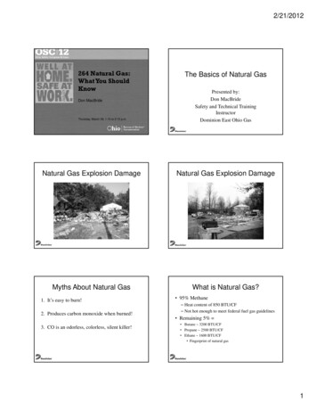
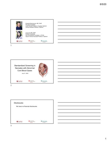
CLEARANCES TO COMBUSTIBLE MATERIALSUPFLOW & PRIGHT SIDEHORIZONTALAPPLICATIONSVENTVENTLEFT SIDEBACKTOPOperation of Furnace During ConstructionSIDELeft Side. 0 InchesTop.0 InchesRight Side. 0 InchesFront. †4 InchesVent. 0 InchesBack. 0 InchesAllow 24 in. minimum clearance for servicing. Recommendedclearance is 36 in.†Figure 1. Minimum Clearances toCombustible MaterialsThe ductwork should be appropriately sized to the capacityof the furnace to ensure its proper airflow rating. Forinstallations above 2,000 ft., the furnace should have asea level input rating large enough that it will meet theheating load after deration for altitude.Installation in a GarageWARNING:Do not place combustible materials on or againstthe furnace cabinet or within 6 inches of thevent pipe. Do not place combustible materials,including gasoline or any other flammablevapors and liquids, in the vicinity of the furnace.This gas-fired furnace may be installed in a residentialgarage with the provision that the burners and igniterare located no less than 18 inches (457mm) above thefloor. The furnace must be located or protected to preventphysical damage by vehicles.Failure to follow these instructions will void thefactory warranty and may significantly reducethe life or the performance of the furnace, and/or result in other unsafe conditions. It is theresponsibility of the installing contractor toinsure these provisions are met.Operating gas furnaces in construction environments cancause a variety of problems with the furnace. Proper useof commercial portable space heating equipment duringconstruction is recommended. This gas furnace may beused during construction if it is not in violation of anyapplicable codes and the following criteria are met: The installation must meet all applicable codes. Thefurnace must be permanently installed according tothe instructions with the furnace including electricalsupply, gas supply, duct work and venting. The furnacemust be controlled by a thermostat properly installedaccording to the instructions supplied with the furnaceand thermostat. The installation must include a properlyinstalled filter in the return air system with no by-passair. The filter must be inspected frequently and replacedwhen necessary. Combustion air must be supplied from outside thestructure and located such that dust and gasesfrom construction activity are not introduced into thecombustion system. Before occupying the structure: The filter must bereplaced or cleaned, the duct work must be inspectedand cleaned of any construction debris, and the furnacemust be cleaned and/or repaired if found to be dirty,damaged, or malfunctioning in any way by a qualifiedHVAC technician. The furnace shall be inspected andapproved by applicable local authority even if thisrequires redundant inspections. Serial numbers for furnaces used during constructionmust be submitted in writing (fax and email alsoacceptable). This information will be used to track thelong-term affects of the use during construction onfurnaces. Proof of this submittal shall be available forthe final inspection of the furnace prior to occupancy. This furnace is designed to operate with return airtemperatures in ranges normally found in occupiedresidences, including setbacks. Minimum continuousreturn temperature must not fall below 60 F (15 C).Occasionally a temporary return temperature of 55 F(12 C) is acceptable. However, operation with a returntemperature below 55 F (12 C) is not allowed.5
COMBUSTION AIR & venting REQUIREMENTSWARNING:Carbon monoxide poisoning hazardFailure to follow the steps outlined belowfor each appliance connected to the ventingsystem being placed into operation couldresult in carbon monoxide poisoning or death.The following steps shall be followed witheach individual appliance connected to theventing system being placed in operation,while all other appliances connected to theventing system are not in operation:1. Seal any unused openings in the venting system.2. Inspect the venting system for proper size andhorizontal pitch, as required in the National FuelGas Code, ANSI Z223.1/NFPA 54 or the CSA B149.1,Natural Gas and Propane Installation Codes andthese instructions. Determine that there is noblockage or restriction, leakage, corrosion andother deficiencies which could cause an unsafecondition.3. As far as practical, close all building doors andwindows and all doors between the space in whichthe appliance(s) connected to the venting systemare located and other spaces of the building.4. Close fireplace dampers.5. Turn on clothes dryers and any appliance notconnected to the venting system. Turn on anyexhaust fans, such as range hoods and bathroomexhausts, so they are operating at maximumspeed. Do not operate a summer exhaust fan.6. Follow the lighting instructions. Place theappliance being inspected into operation.Adjust the thermostat so appliance is operatingcontinuously.7. Test for spillage from draft hood equippedappliances at the draft hood relief opening after 5minutes of main burner operation. Use the flameof a match or candle.8. If improper venting is observed during any of theabove tests, the venting system must be correctedin accordance with the National Fuel Gas Code,ANSI Z223.1/NFPA 54 and/or CSA B149.1, NaturalGas and Propane Installation Codes.9. After it has been determined that each applianceconnected to the venting system properly ventswhen tested as outlined above, return doors,windows, exhaust fans, fireplace dampers andany other gas-fired burning appliance to theirprevious conditions of use.6AVERTISSEMENT:RISQUE D’EMPOISONNEMENT AUMONOXYDE DE CARBONEdLe non-respect des consignes suivantes portantsur chacun des appareils raccordés au systèmed’évacuation mis en service pourrait entraînerl’empoisennement au monoxyde de carbone oula mort. Les consignes suivantes doivent êtreobservées pour chaque appareil raccordé ausystème d’évacuation mis en service si les autresappareils raccordés au système ne sont pas enservice:1. Sceller toute ouverture non utilisée de la systémed’évacuation;2. S’assurer que la systéme d’évacuation présente desdimensions et une pente horizontale conformes à lanorme ANSI Z223.1/NFPA 54, intitulée National FuelGas Code ou aux codes d’installation CSA-B149.1,ainsi qu’aux présentes instructions. S’assurerque la systéme d’évacuation n’est pas bloquée,restreinte, corrodée, qu’elle ne fuit pas et qu’ellene présente aucun autre défaut potentiellementdangereux;3. Dans la mesure du possible, fermer toutes lesportes et fenêtres du bâtiment, et toutes les portesentre la pièce où se trouve l’appareil raccordé àla systéme d’évacuation et les autres pièces dubâtiment.4. Fermer les registres des foyers;5. Mettre en service les sécheuses et tout autreappareil qui n’est pas raccordé à la systémed’évacuation. Faire fonctionner à régime maximaltout ventilateur d’évacuation, tel que les hottes decuisinière et les ventilateurs de salles de bains. Nepas mettre en service les ventilateurs d’été.6. Respecter les instructions d’allumage. Mettre enservice l’appareil à l’essai. Régler le thermostatde manière à ce que l’appareil fonctionne sansinterruption;7. Vérifier s’il y a débordement à l’orifice d’évacuationdu coupe tirage des appareils dotés d’un coupetirage 5 minutes après l’allumage du brûleurprincipal. Utiliser la flamme d’une allumette oud’une chandelle.8. Si l’on constate, au cours de l’un des essais quiprécèdent, que l’évacuation est déficiente, corrigerle système d’évacuation conformément à la normANSI Z223.1/NFPA 54, National Fuel Gas Code, et(ou) aux codes d’installation CSA B149.1.9. Après avoir déterminé que tous les appareilsraccordés à la systéme d’évacuation évacuentcorrectement tel que prescrit ci-dessus, rouvrir lesportes et les fenêtres et remettre les ventilateursd’évacuation, les registres de foyers et toutautre appareil fonctionnant au gaz à leur état defonctionnement initial.
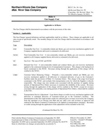
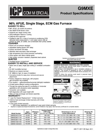
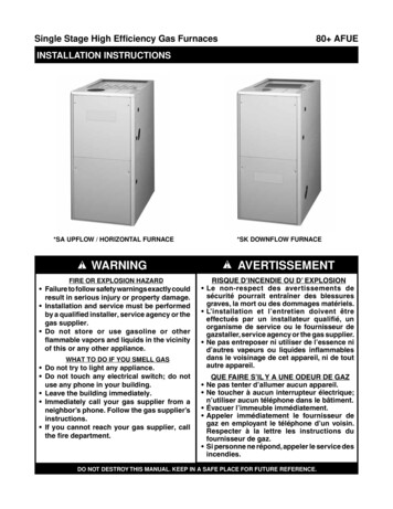
Important Information Provisions must be made during the installationof this furnace that provide an adequate supplyof air for combustion. Furnace installation usingmethods other than those described in the followingsections must comply with the National Fuel GasCode (NFGC) and all applicable local codes. Instructions for determining the adequacy ofcombustion air for an installation can be found in thecurrent revision of the NFGC (ANSI Z223.1 / NFPA54).Consult local codes for special requirements.Theserequirements are for US installations as found inthe NFGC. The requirements in Canada (B149.1) are structureddifferently. Consult with B149.1 and local codeofficials for Canadian installations.Air From InsideIf combustion air is taken from the heated space, the twoopenings must each have a free area of at least 1 in2 per1,000 Btuh of total input of all appliances in the confinedspace, but not less than 100 in2 of free area. See Figure2 and the example below.Example:If the combined input rate of all appliances is less thanor equal to 100,000 Btuh, each opening must have afree area of at least 100 in2. If the combined input rateof all appliances is 120,000 Btuh, each opening musthave a free area of at least 120 in2.Vent orChimneyCAUTION:Exhaust fans, clothes dryers, fireplaces andother appliances that force air from the houseto the outdoors can create a negative pressureinside the house, resulting in improper furnaceoperation or unsafe conditions such as flame rollout. It is imperative that sufficient air exchangewith the outdoors is provided to preventdepressurization. Additional information abouthow to test for negative pressure problems canbe found in the NFGC.Air openings on top of the furnace and openings in closetdoors or walls must never be restricted. If the furnace isoperated without adequate air for combustion, the flameroll-out switch will open, turning off the gas supply to theburners. NOTE: This safety device is a manually resetswitch. DO NOT install jumper wires across theseswitches to defeat their function or reset a switchwithout identifying and correcting the fault condition.If a switch must be replaced, use only the correct sized partspecified in the Replacement Parts List provided online.Installation In A Confined SpaceA confined space is an area with volume less than 50cubic feet per 1,000 Btuh of the combined input rates ofall appliances drawing combustion air from that space.Furnace closets, small equipment rooms and garages areconfined spaces. Furnaces installed in a confined spacewhich supply heated air to areas outside the space mustdraw return air from outside the space and must have thereturn air ducts tightly sealed to the furnace.The required sizing of these openings is determined bywhether inside or outside air is used to support combustion,the method by which the air is brought to the space, andby the total input rate of all appliances in the space. Inall cases, the minimum dimension of any combustion airopening is 3 inches.NOTES:Each opening mustbe at least 100 sq. in.or 1 sq. in. per 1,000Btuh of total input rating,whichever is greater.12" Max.SeeNotesFurnaceOpenings must start atno more than 12 inchesfrom the top and bottomof the enclosure.See NotesWaterHeater12” Max.Total Input Rating(Btuh)Minimum Free Area(Each Opening)Round 0160,000100 in2100 in2100 in2100 in2120 in2140 in2160 in212 inches12 inches12 inches12 inches13 inches14 inches15 inchesFigure 2. Combustion Air Drawn from InsideOutdoor Air from a Crawl Space or Vented AtticWhen the openings can freely exchange air with theoutdoors, each opening shall have a minimum free areaof 1 in2 per 4,000 Btuh of total appliance input. Theopenings shall exchange directly, or by ducts, with theoutdoor spaces (crawl or attic) that freely exchange withthe outdoors (Figure 3, page 8).Outdoor Air Using Vertical DuctsIf combustion air is taken from outdoors through verticalducts, the openings and ducts must have a minimumfree area of 1in2 per 4,000 Btuh of total appliance input.In installations drawing combustion air from a ventilatedattic, both air ducts must extend above the attic insulation.See Figure 4 (page 8).Outdoor Air Using Horizontal DuctsIf combustion air is taken from outdoors through horizontalducts, the openings and ducts must have a minimum freearea of 1in2 per 2,000 Btuh of total appliance input. SeeFigure 5 (page 8).7
Ventilation louversat each end of atticOutlet air duct must beat least 1 sq. in. per4,000 Btuh of totalinput rating. Mustextend above atticinsulationFurnaceInlet air duct must be atleast 1 sq. in. per 4,000Btuh of total input rating.Crawl Space12" Max---Figure 3. Combustion Air Drawn from a CrawlSpace or Vented Attic---WaterHeaterFurnaceInlet and OutletDucts mustextend aboveattic insulation.Inlet Air Duct mustbe at least 1 sq. in.per 4,000 Btuh oftotal input rating.12" MaxTotal Input Rating(Btuh)Minimum Free Area(Each Opening)Round 0160,000100 in2100 in2100 in2100 in2120 in2140 in2160 in212 inches12 inches12 inches12 inches13 inches14 inches15 inchesFigure 4. Combustion Air Drawn from OutsideThrough Vertical Ducts---Water HeaterMinimum Free Area(Each Opening)Round 0160,00010 in215 sin220 in225 in230 in235 in240 in25 inches6 inches7 inches8 inches9 inches10 inches10 inchesOutlet Air Duct mustbe at least 1 sq. in.per 4,000 Btuh oftotal input rating.AtticInsulationAir DuctNOTE: Eachopening tooutside mustbe at least 1sq. in. per 2,000Btuh of totalinput rating.Total Input Rating(Btuh)Ventilation Louvers a
A gas-fired furnace for installation in a residential garage must be installed as specified on page 5. This furnace is not approved for installation in mobile homes. Installing this furnace in a mobile home could cause fire, property damage, and/or personal injury. If the furnace is installed in a confined space, it is