Transcription
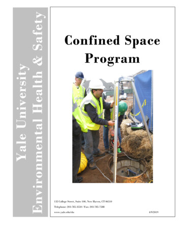
Science Champion: Dr. Lori S. Glaze, NASA’s Goddard Space Flight CenterStudy Point of Contact: Michael L. Adams, NASA’s Goddard Space Flight CenterMission Concept Study Report to the NRC Decadal Survey Inner Planets PanelVenus Mobile ExplorerNational Aeronautics and Space AdministrationNASA-GSFC JPL-Caltech NASA-ARCDecember 18, 2009
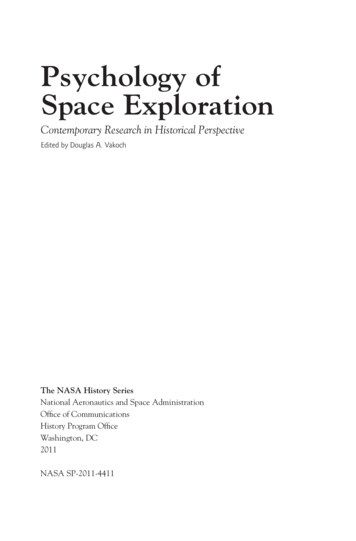
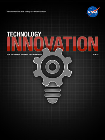
VMEVenus Mobile Explorerfact sheetMission Concept Study Report to the NRC Decadal SurveyInner Planets Panel December 18, 2009Concept Maturity Level: 4 Cost Range: Low End FlagshipGSFC JPL ARCNominal Mission: Atlas V 551 Short FairingLaunch Vehicle Type II trajectory Launch on 5/27/2023 Venus fly-by 10/27/2023 Landed science 2/15/2024- atmospheric chemistry- surface chemistry in 2 locations- 8 - 16 km aerial imaging traverseMission DrivingScience ObjectivesLeft: Artist’s rendition of early Venus with possible large oceans anda significant hydrologic cycle; Right: Venus today with a dry, thickCO2 greenhouse atmosphere resulting in surface temperatures of450 C and pressures in excess of 90 bar.MeasurementInstrumentFunctional RequirementDetermine the origin and evolutionof the Venus atmosphere, and ratesof exchange of key chemical speciesbetween the surface andatmosphereIn situ measurements of Noblegas isotopes, trace gas mixingratios and trace gas isotopicratiosNeutral Mass Spectrometer(NMS) combined with TunableLaser Spectrometer (TLS)In situ sampling of the atmosphereas functions of altitude and timeCharacterize fundamental geologicunits in terms of major rock formingelements, minerals in which thoseelements are sited, and isotopesIdentify mineralology andelemental chemistry ofsurface rocks in 2 locationsseparated by 8 kmLand in 2 locations, 2 mLaser Raman/Laser InducedBreakdown Spectrometer (LIBS) path-length for compositionalobservation; stable platform formeasurement durationCharacterize the geomorphologyand relative stratigraphy of majorsurface unitsAirborne near IR imagingalong a transect 8 km inlength, at 5 m spatialresolutionNear infrared ( 1.1 micron)imager (FOV TBD, and SNR 100)Lander Aeroshell (Cruise Configuration)The innovativecompact design ofthe science payloadinto a centralcylinder surroundedby a toroidalpressurant tank andcapped by themetallic bellows,allows the VME to beaccommodated in anaccepted aeroshellgeometry.Near-surface aerial mobility; 45 solar incidence, contiguous imagesof the surface during aerialtraverse; 5 hour near surfaceoperational lifetimeGondola in Landed Configuration (Transparent View)Cylindricalgondola carriesthe sciencepayload in athermallycontrolledenvironment.Compact metallic bellowsexpand when filled withhelium to providebuoyancy.3FT1MToroidal pressurant tank carries heliumused to inflate the bellows; tank is left onthe surface when gondola ascends.Probe timeline illustrates configuration changes throughout science mission duration, Wind drives the neutrally buoyant aerial traverse.Carrier lImage on Land, SurfaceDescentRockAnalysisFloat with Wind, ImageLand, SurfaceRockAnalysis8 - 16 kmRelease Probe5 days before100 km alt60 km alt50 km alt15 km altT 0 to20 min5 km altT 246 to300 min
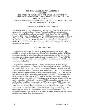
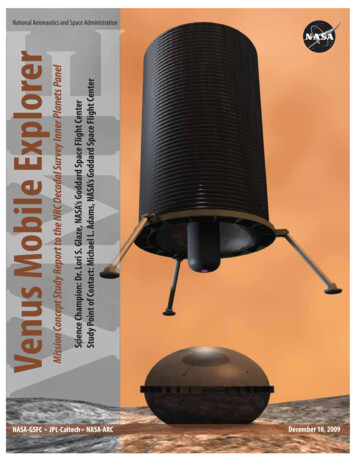
ProbeExploded view of Carrier Spacecraft,Aeroshell, Bellows System and GondolaPressurantTank withInsulationSolarPanelsBackshell& ParachuteTop of Gondola(Dome &Lander legs)Carrier SpacecraftCarrier Spacecraft1 m X-bandHGA3 m S-band HGACruise Configuration3FTGondola’sPressure Vessel1MBellowsAfter Probe ReleaseCarrier hPurpose3 m HGA meshS-bandProbe to Carrier uplink2 omni-directionalX-bandCarrier to Earth contingency1 m HGA solidX-bandCarrier to Earth ScienceScience Concept of OperationsASI100%10%100% duty cycle10% duty cycleNMSTLSImagerImage every 1.7 kmInitial DescentAscentFinalTransect ImagingRamanLIBSMagReleaseBellowsInflateBellows& AscendAnalyzeSurface andTransmit DataSend Sample,Descent ImageryDataSecondLandingLandingAnalyze Surface-1 HourLanding1 Hour2 Hours3 Hours4 Hours5 HoursASI Atmospheric Structure Investigation; Mag Magnetometer1 kmMass Breakdown 12 kmAscentImagesFinalDescentImagesTransect Images2 m res2 km52 ImagesInitial DescentNominal example of imaging sequence assuming 12 km aerial traverse. IR Images are taken on initial descent from 15 km to the surface(blue), on ascent (red), as the gondola floats with the wind under the bellows (yellow) and on final descent (green), collecting 52 images.ComponentCBE[kg]LanderLander Science PayloadLander erBellowsAeroshellSpacecraftSatellite (S/C Probe) Dry Mass13903146927051113348908768463112Allow MaxMass[%] 6147441132113911004021
Ve n u s Mo b i l e Ex p l o re r ( VME)Table of ContentsExecutive Summary . . . . . . . . . . . . . . . . . . . . . . . . . . . . . . . . . . . . . . . . . 11.0 Scientific Objectives . . . . . . . . . . . . . . . . . . . . . . . . . . . . . . . . . . . . . . . 21.1 Science Questions and Objectives . . . . . . . . . . . . . . . . . . . . . . . . . . . . . . . . 21.2 Science Traceability . . . . . . . . . . . . . . . . . . . . . . . . . . . . . . . . . . . . . . . 31.3 Study Objectives . . . . . . . . . . . . . . . . . . . . . . . . . . . . . . . . . . . . . . . . . 32.0 High-Level Mission Concept . . . . . . . . . . . . . . . . . . . . . . . . . . . . . . . . . . 42.1 Overview . . . . . . . . . . . . . . . . . . . . . . . . . . . . . . . . . . . . . . . . . . . . . 42.2 Concept Maturity Level . . . . . . . . . . . . . . . . . . . . . . . . . . . . . . . . . . . . . 53.0 Technical Overview . . . . . . . . . . . . . . . . . . . . . . . . . . . . . . . . . . . . . . . 53.1 Instrument Payload . . . . . . . . . . . . . . . . . . . . . . . . . . . . . . . . . . . . . . . 53.2 Flight System . . . . . . . . . . . . . . . . . . . . . . . . . . . . . . . . . . . . . . . . . . 63.2.1 Concept of Operations and Mission Design . . . . . . . . . . . . . . . . . . . . . . . . 63.2.2 Spacecraft . . . . . . . . . . . . . . . . . . . . . . . . . . . . . . . . . . . . . . . . . 93.2.3 Entry and Descent Element . . . . . . . . . . . . . . . . . . . . . . . . . . . . . . . 103.2.4 Lander . . . . . . . . . . . . . . . . . . . . . . . . . . . . . . . . . . . . . . . . . . 103.2.4.1 Lander Mechanical System . . . . . . . . . . . . . . . . . . . . . . . . . . . . . 103.2.4.2 Lander Mobility System . . . . . . . . . . . . . . . . . . . . . . . . . . . . . . 123.2.4.3 Lander Thermal System . . . . . . . . . . . . . . . . . . . . . . . . . . . . . . 143.2.4.4 Lander Avionics . . . . . . . . . . . . . . . . . . . . . . . . . . . . . . . . . . 153.2.4.5 Lander Communications . . . . . . . . . . . . . . . . . . . . . . . . . . . . . 163.2.4.6 Lander Power . . . . . . . . . . . . . . . . . . . . . . . . . . . . . . . . . . . 163.2.5 Lander Mass, Power, Data Rate . . . . . . . . . . . . . . . . . . . . . . . . . . . 173.3 Ground Systems . . . . . . . . . . . . . . . . . . . . . . . . . . . . . . . . . . . . . . . . 173.4 Key Trades . . . . . . . . . . . . . . . . . . . . . . . . . . . . . . . . . . . . . . . . . . . 183.4.1 Key Architecture Trades . . . . . . . . . . . . . . . . . . . . . . . . . . . . . . . . . 183.4.2 Instrumentation Trades . . . . . . . . . . . . . . . . . . . . . . . . . . . . . . . . . 193.4.3 Flight Trajectory/Launch Opportunities Trade . . . . . . . . . . . . . . . . . . . . . . 193.4.4 Power System Trade . . . . . . . . . . . . . . . . . . . . . . . . . . . . . . . . . . . 203.4.5 Other Trades . . . . . . . . . . . . . . . . . . . . . . . . . . . . . . . . . . . . . . . 203.5 Risk List . . . . . . . . . . . . . . . . . . . . . . . . . . . . . . . . . . . . . . . . . . . . 223.6 Technology Maturity . . . . . . . . . . . . . . . . . . . . . . . . . . . . . . . . . . . . . . 244.0 Development Schedule and Schedule Constraints . . . . . . . . . . . . . . . . . . . . . . 244.1 High-Level Mission Schedule . . . . . . . . . . . . . . . . . . . . . . . . . . . . . . . . . 244.2 Technology Development Plan . . . . . . . . . . . . . . . . . . . . . . . . . . . . . . . . . 245.0 Mission Life-Cycle Cost . . . . . . . . . . . . . . . . . . . . . . . . . . . . . . . . . . . . 255.1 Costing Methodology and Basis of Estimate . . . . . . . . . . . . . . . . . . . . . . . . . . 255.2 Cost Estimate . . . . . . . . . . . . . . . . . . . . . . . . . . . . . . . . . . . . . . . . . 256.0 Conclusions . . . . . . . . . . . . . . . . . . . . . . . . . . . . . . . . . . . . . . . . . . 26i
Ve n u s Mo b i l e Ex p l o re r ( VME)7.0 Open Topics for Further Concept Development . . . . . . . . . . . . . . . . . . . . . . . 268.0 Acknowledgements . . . . . . . . . . . . . . . . . . . . . . . . . . . . . . . . . . . . . . 27AppendicesAppendix A - Acronyms ListAppendix B - Referencesii
Ve n u s Mo b i l e Ex p l o re r ( VME)EXECUTIVE SUMMARYNASA Headquarters commissioned the Goddard Space Flight Center’s (GSFC) ArchitectureDesign Lab with a rapid mission architecturestudy to support the National Research Council’s 2010 Planetary Decadal Survey Inner PlanetsPanel. The purpose of the study was to determinewhether a Venus mission with surface, or nearsurface, mobility and realistic operational lifetimecould achieve meaningful surface science at twoor more independent locations separated by several kilometers on a budget comparable to a NewFrontiers cost envelope. The Inner Planets Panelwas particularly interested in a metallic bellowsconcept for aerial mobility and the use of Radioisotope Power Systems (RPS) for power and activecooling. Following completion of this study, theVenus Mobile Explorer (VME) Concept Maturity Level (CML) is raised from 2 to 4. Based onanalyses of the mechanical, thermal, power, avionics, and communication designs for the VMEprobe and the carrier spacecraft, the study teamcan state with confidence that a Venus missionusing the metallic bellows architecture for shortlived aerial mobility is technically feasible. However, the cost estimate for the nominal baselineVME implementation ( 1.1B - 1.7B FY15, notincluding launch vehicle) is at the low end of theFlagship range, beyond what the study team considers plausible for New Frontiers missions in thecoming decade. The cost is driven by the metallicbellows and supporting mechanisms for its operation. Technology development, accommodation,and complex integration also contribute to thehigh cost of the probe.The VME mission concept affords unique science opportunities and vantage points not previously attainable at Venus. The ability to characterize the surface composition and mineralogy in twolocations within the Venus highlands (or volcanicregions) will provide essential new constraints onthe origin of crustal material, the history of water in Venus’ past, and the variability of the surface composition within the unexplored Venusianhighlands. As the VME floats ( 3 km above thesurface) between the two surface locations, it offersnew, high spatial resolution, views of the surface atnear infrared (IR) wavelengths. These data provideinsights into the processes that have contributedto the evolution of the Venus surface. The science objectives are achieved by a nominal payloadthat conducts in situ measurements of noble andtrace gases in the atmosphere, conducts elementalchemistry and mineralogy at two surface locationsseparated by 8–16 km, images the surface ondescent and along the airborne traverse connecting the two surface locations, measures physicalattributes of the atmosphere, and detects potentialsignatures of a crustal dipole magnetic field.The study team developed an elegant, volumeefficient cylindrical gondola to accommodate thescience payload in a thermally controlled environment. An innovative, highly compact design surrounds the gondola with a toroidal pressure tankcapped with the bellows, enabling the entire landersystem to fit in an aeroshell with heritage geometry. The thermal design uses heat pipes and phasechange material that enable the gondola electronicsand instruments to survive 5 hours near the Venussurface, thus providing sufficient time for surfacechemistry and an aerial traverse 8 km in the current-like winds. The study team also determinedthat using an RPS device for power and coupledactive cooling requires considerable developmentcosts and increases the system mass well beyondNew Frontiers launch vehicle capabilities.Launched on an Atlas V 551 in either 2021or 2023, the carrier spacecraft carries the VMEprobe to Venus on a Type II trajectory. After release from the carrier, the VME probe enters theatmosphere, descends on a parachute briefly, andthen free-falls to the surface. Science is conductedon descent and at the surface. While collectingdata at the first site, the bellows are filled withhelium and when buoyant, rise with the gondola,leaving the helium pressure tank on the surface.Driven by the ambient winds, the gondola floatswith the bellows for 220 minutes, conductingadditional science. At the completion of the 8–16km aerial traverse, the bellows are jettisoned andthe gondola free falls back to the surface, where final surface science measurements are performed.The total mission time in the Venus atmosphereis 6 hours, which includes 5 hours in the nearsurface environment. The VME probe transmitsdata to the flyby carrier spacecraft continuouslythroughout the 6-hour science mission. Afterlosing contact with the VME probe, the carrierspacecraft then relays all data back to Earth.VME feasibility within the coming decade depends on advancements in four key technologyareas, 1) raising the Technology Readiness Level(TRL) of the metallic bellows system, includingthe helium pressure tank and plumbing, to TRL6, 2) verifying the Raman/LIBS implementationand calibrated operation in the Venus surface environment, 3) developing reliable Venus grademechanisms, and 4) developing techniques to en-1
Ve n u s Mo b i l e Ex p l o re r ( VME)sure safe landing in potentially rugged terrains (atlander scales).The bellows mobility concept presented inthis report is unable to perform surface sciencein more than two locations. Multiple landersmay offer a lower risk alternative approach to theVME at a comparable cost and could access morethan two locations.1.0 Scientific Objectives1.1 Science Questions and ObjectivesVenus is often referred to as Earth’s sister because of their similar size and position within thesolar system. Yet, despite their similar origins, thetwo planets have apparently followed very different evolutionary paths. In the 1970s and 1980s,the plains regions were explored by multiple Soviet Venera Landers, and NASA launched thePioneer-Venus mission (orbiter plus four atmospheric probes). The NASA Magellan mission(1990-1994) consisted of an orbiting spacecraftwith a moderate resolution synthetic aperture radar and radar altimeter to globally map the surface. ESA’s Venus Express (VEx) is currently in orbit observing polar cloud dynamics and JAXA isexpected to launch Akatsuki in 2010 to monitorequatorial cloud dynamics and weather, complementing VEx’s measurements. In addition, Earthbased observations using advanced polarimetricradar mapping have contributed significantly toour understanding of Venus.Missions that have landed on Venus are listedin Table 1, highlighting the state of the art nature of VME driven by its science requirement tostudy the Venus surface in two different surfacelocations. The longer the surface operations, thegreater the departure from heritage missions, butthe higher the likelihood of exploring geologicallydistinctive surface units.The highest priority science objectives for Venus are expressed in the Venus Exploration Analysis Group (VEXAG) Goals, Objectives, Investigations, and Priorities document [2009], and arereiterated in the Venus Flagship Science and Technology Definition Team Final Report [2009].The VME concept developed in this study is amission to explore the surface and near surfaceenvironments of Venus to determine surface mineralogy and associated compositional variations,to understand chemical exchange mechanismsbetween the surface and atmosphere, to constrainwhether a widespread ocean (with its associatedhydrologic cycles and mineralogies) existed andwas subsequently lost, and whether Venus couldTable 1: Historic capabilities of static landers and atmosphericprobes at Venus. The longest surface survival was just over 2 hours,and the most recent mission to touch the surface of Venus waslaunched in 1984.SurfaceSurfaceSurfaceLandedSurvival Pressure Thermal SampleMissions Launch Time (min) Vessel Control AcquisitionVenera 7197023NoNoNoVenera 8197250NoYesNoVenera 9197553NoYesNoVenera 10197565NoYesNoVenera 11197895NoPCMNoVenera 121978110NoPCMNoPioneer197860YesNoNoVenusVenera 131981127YesPCMYesVenera 14198157YesPCMYesVega 2198456YesPCMYesLanderhave ever maintained surface conditions capableof supporting life. VME’s primary science objectives are a subset of those defined by VEXAG andare shown, in priority order, in Table 2.The scientifically compelling highland regionsknown as “complex ridged terrain” (or “tessera”)hold the most potential for providing new insightinto the thermal evolution of the Venus interior,including the possibility of the preservation ofancient continental crust and the role of water inVenus’ past. Recent results from VEx indicate thatthe highlands may have a higher surface albedo inthe near IR than the basaltic plains, suggestingthe highlands have a more evolved composition.Furthermore, because the basaltic plains havealready been explored many times by the SovietVenera and Vega missions, the tessera (or possibly large volcanic centers) will provide the highestprobability of compositional diversity comparedto previous measurements. The ability to samplethe major elements and mineralogy (particularlySiO2, FeO, MgO, S-bearing, and OH-bearingminerals) of such surfaces in multiple locationsdecreases statistical sampling uncertainty.Imaging these unique terrains in optical wavelengths at very high spatial resolutions will provide new insights into the physical processes thathave contributed to the evolution of the Venussurface. Even a relatively short aerial traverseacross the tessera can provide details regarding thescales of geomorphic roughness and evidence forlocalized tectonic deformation, and possibly evidence of mass-wasting in areas with topographicvariability. Because of the super-critical CO2 lower atmosphere, illumination is extremely diffuse(dominated by Rayleigh scattering) and there are2
Ve n u s Mo b i l e Ex p l o re r ( VME)Table 2: Science traceability of primary science objectives (left) to functional mission requirements (right).Science ObjectiveDetermine whether Venus has a secondaryatmosphere resulting from late bombardmentand the introduction of significant outer-solarsystem materials, including volatilesCharacterize major geologic units in termsof major elements, rock forming minerals inwhich those elements are sited, and isotopesMeasurementInstrumentMeasure atmospheric Noble gas Neutral Massisotopes in situSpectrometerFunctional RequirementIn situ sample of atmosphere (1 bulk sample ondescent)Identify mineralogy (SiO2, FeO, Raman/LIBSMgO, sulfur bearing, OH-bearing)and elemental chemistry ofsurface rocks in 2 surfacelocations (separated by 8 km)Land in 2 locations; 2 m path-length forobservation; stable platform for measurementdurationCharacterize the morphology and relativestratigraphy of surface unitsNear IR imaging along anairborne traverse 8 kmin length, at 5 m spatialresolutionDetermine the rates of exchange of keychemical species ( S, C, O) between thesurface and atmosphereMeasure trace gases in the near Neutral Masssurface atmosphere (within one Spectrometer; Tunablescale height)Laser SpectrometerNear surface aerial mobility (bellows); Nadir-lookingposition on gondola to image the surface; platformstability for non-blurred images; 45 solar incidenceangle, acquire contiguous images of the surface duringaerial traverse 8 km (requires 5 hr lifetime)In situ sampling of atmosphere as functions of altitudeand time [f (z, t) ]Place constraints on the size and temporalextent of a possible ocean in Venus’s pastNear-infrared ( 1.1micron) imager with fieldof view TBD and SNR 100Measure D/H ratio in atmospheric Neutral Masswater, at least twiceSpectrometer; TunableLaser SpectrometerCharacterize variability in physical parameters Atmospheric temperature,Temperature, pressure,of the near surface atmosphere (pressure,pressure, windsaccelerometers, USOtemperature, winds)Measure ambient magnetic field from low- Detection of existence or absence Flux-gate magnetometerand near-surface elevationsof surface magnetic signalno shadows at the Venus surface. In addition, thevolcanic surfaces of low albedo basalt are monochromatic with very low contrast, resulting in theneed for a very high signal to noise ratio (SNR) inany imaging system. The higher near IR reflectivity of the highland regions, as observed by VEx,may result in less stringent requirements for imaging SNR, making these areas both scientificallyinteresting and technically more feasible.1.2 Science TraceabilityTable 2 traces the primary science objectivesto the key measurements needed to addresseach, as a function of required vantage point.The third column of Table 2 indicates nominalinstrumentation that could satisfy the measurement requirements (see Section 3.1 for details).For surface elemental chemistry and mineralogy, the team selected a laser Raman/Laser Induced Breakdown Spectroscopy (LIBS) remotesensing approach over more traditional X-rayDiffraction/X-ray Fluorescence Spectroscopy(XRD/XRFS) because it offers implementationadvantages (i.e., absence of sample acquisition,handling, and transfer to an XRD/XRFS). Adiscussion of this key trade is provided in Section 3.4.2. The time required to complete thetwo surface chemistry measurements, the aerialIn situ sampling of atmosphere [f (z, t) ]In situ measurements of T/P, Doppler measurementusing communications system for windsMust be able to detect surface “signal” above a 5-10nTthreshold, over and above any payload “noise”traverse between the two landing sites, and theuplink of all images to the carrier spacecraft,drives the operational lifetime of the VME to 5 hours in the near surface environment. The5 hours of near surface operations combinedwith the 1 hour initial atmospheric descent,results in a requirement for 6 hours continuouscommunication with the carrier spacecraft (atleast 10 above the horizon) as it flies by Venus.Neither the surface chemistry nor the imagingtraverse place unusual requirements on landingprecision. A typical Venus target landing error ellipse on the order of 75 km x 150 km is adequatefor targeting large tessera regions, which are often hundreds to thousands of km in diameter.1.3 Study ObjectivesThe driving science requirements that led tothe VME design presented in this study are: 1) elemental and mineralogical measurements in twodifferent locations separated by 8 km, and, 2)contiguous nadir-viewing, high spatial resolutionimages of the surface along the 8 km transverseconnecting the two surface locations. The finalsignificant driver for this study was to develop aconcept that minimized mission cost, and thattherefore might enable VME to remain in a NewFrontiers cost envelope for the coming decade.3
Ve n u s Mo b i l e Ex p l o re r ( VME)The contiguous images requirement drove thestudy team toward selecting a mobility platformwith multiple-landing capabilities. This allows forthe two surface measurements to be interpretedin the context of macro-scale Venus geology. Aspotential modes of mobility on the Venus surfaceare extremely limited due to the Venus environment, the Inner Planets Panel (IPP) recommended examining a previously-conceived metallic bellows balloon concept [Kerzhanovich et al., 2005].While this concept was not explicitly addressedby the 2009 Venus Flagship mission study, it wasincluded in the 2006 NASA Solar System Exploration roadmap, and has been contemplatedwithin Venus exploration scenarios studied by thecommunity for at least 5 years.An important component of the IPP study request was to better understand the limitation ofRPS technology coupled with active cooling andwhether such technology could be used to extendthe life of a VME-type mission. Unfortunately,no such capability currently exists for the nearsurface Venus environment.The Decadal Survey IPP also expressed a stronginterest in tessera terrain exploration because ofthe regions’ potential link to early crustal genesis orthe role of water in composition evolution. Theseunique highland regions are rugged, and typicallystand 1.5-2 km above the surrounding plains. Forthis rapid mission design study, target surface elevations of 2 km above mean planetary radius(AMPR) were assumed, but flight dynamics werenot optimized for a specific target location.2.0 High-Level Mission Concept2.1 OverviewThe VME mission concept was arrived at afterreviewing various mobility options and receivingdirection from the IPP to study the feasibility ofa metallic bellows flotation system using positivebuoyancy and near surface winds for mobility.The VME Mission’s space segments consist of aprobe and flyby carrier spacecraft that is also used asa communications relay (see Figure 1). The probeis comprised of two top level elements, the Entryand Descent Element (EDE), which includes theaeroshell and parachute systems, and the Lander.The lander has two major systems: 1) the gondolasystem that carries the science instruments andsubsystems inside a thermally protected pressurevessel, and, 2) the bellows aerial mobility system,including the bellows and the inflation subsystems.The design concepts for each mission element andsystem are discussed in Section 3.2.Table 3: Carrier Spacecraft Complexity.SubsystemBrief Summary Of ConceptSystemsHeritage spacecraft designs can be utilized,simple Interfaces to ProbeFlight Dynamics Driving requirement to release probe onVenus entry interface trajectoryAttitude Control Control SC with ¼ lb thrusters and spin upSubsystemprobe to 5 rpm with thrustersPropulsionDelta V maneuvers relatively small forplanetary missionsAvionicsLow data rateCommunications Two antennas simplify operations; 3 meterlightweight S-band HGA to communicatewith Probe and a 1 meter X-band HGA forcommunication with EarthPowerLow power needs allow for small solar arraysMechanicalDriving requirement to minimize S/C mass,allowing for larger probeThermalHeritage thermal designs can be utilizedIntegration and Most testing can be completed withoutTestprobe, facilities exist for S/C derateLowLowCarrier Spacecraft: The three-axis stabilized carrier spacecraft (Figure 1) performs three functions: 1) delivers the probe on an interplanetarytrajectory to Venus, 2) releases the probe on anappropriately pointing trajectory to enter the Venus atmosphere, and 3) acts as a communicationrelay between the VME and the Earth. Because ofthe flyby trajectory, the required fuel mass is relatively small, thermal and power tasks are simple,and electronics and communication systems arestraightforward. The drivers for the carrier spacecraft design include spinning up the probe to 5RPM prior to release and having a robust structure to support the probe. Table 3 details the subsystem drivers for the Carrier Spacecraft.Probe: The probe is released from the carrier 5days before reaching the Venus atmosphere. Thecommunications system is switched on 1 hour before encountering the atmosphere and will transmit continuously. The aeroshell is designed withapproximately one inch of carbon phenolic mate-PressurantTank withInsulationTop of Gondola(Dome & Lander legs)Gondola’sPressure Vessel1M3FTSolarPanelsBackshell& gure 1: Carrier Spacecraft. and probe, exploded view.4
Ve n u s Mo b i l e Ex p l o re r ( VME)rial that ablates upon entry into the Venus atmosphere, where the probe experiences a decelerationof 157 g (2023 launch) or 167 g (2021 launch).(In all subsequent references to the design, 167g is assumed to be the bounding static structuralload for the probe design.) The heat shield is jettisoned minutes after the parachute system on thebackshell is deployed (at an altitude of 60 km).Following this operation, the backshell and parachute system are released from the lander. Du
National Aeronautics and Space Administration NASA-GSFC JPL-Caltech NASA-ARC December 18, 2009 Venus Mobile Explorer Mission Concept Study Report to the NRC Decadal Survey Inner Planets Panel Science Champion: Dr. Lori S. Glaze, NASA's Goddard Space Flight Center Study Point of Contact: Michael L. Adams, NASA's Goddard Space Flight Center