Transcription
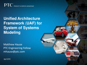
Unified ArchitectureFramework (UAF) forSystem of SystemsModelingMatthew HausePTC Engineering Fellowmhause@ptc.comApril 2016
Agenda What is the UAF? System of Systems Modeling Coverage requirements for SoS Conclusion Questions?2
Why Model Based Systems Engineering (MBSE)? Pictures paint a thousand words– Visio is good at this– Language is not controlled Modeling languages add semantics and constraints– Control what is being said and how it is said MBSE is enabled by SysML*, which is a common language of expressionthat captures:– Structure– Behavior– Requirements Functional Non Functional Models can be quantifiable and executable* Systems Modeling Language (OMG SysML )3
What is UPDM? UPDM is the Unified Profile for DoDAF and MODAF ( NAF DNDAF) UPDM is NOT a new Architectural Framework UPDM is NOT a methodology or a process UPDM is a graphical enterprise modeling language UPDM was developed by members of the OMG with help from industryand government domain experts DOD (US) MOD (UK) SWAF (SwedishArmed Forces) DND (Canada) MITRERaytheonLockheed MartinGeneral DynamicsL3 PTCIBMNo MagicSparxMega4
MBSE and Engineering AnalysisWhy is UPDM so popular with practitioners of MBSE?–No standardized frameworks for MBSE exist–Integration with existing OMG standards, e.g. SysML, UML–Tool vendors support: Implemented in most popular modeling tools:IBM Rhapsody, No Magic MagicDraw, PTC Integrity Modeler–Defense and Industry drivenCommon repository (Integrated Architecture Repository)– Application of engineering analysis methods Impact Analysis Coverage Analysis Trade-off Analysis Behavioral execution Requirements compliance analysis Model-based testing– Interoperability5
Why a Unified Architecture Framework (UAF)? Proliferation of frameworks that UPDM was being asked tosupport Need to support industry and federal usage as well asmilitary–Commercialization, whilst still supporting architect needs Ability to support other frameworks–By Extension–By Mapping6
Why a Unified Architecture Framework Profile (UAFP)*? An MBSE approach to a layered “model of models” (MOM) IDEAS* based format for a Domain MetaModel (DMM) thatallows implementation by non-SysML based tools–Same format as DoDAF, MODAF and NAF UAF enables the development of integrated model layers(e.g., outcomes model layer and a component layer)*UAFP is the planned OMG update to the UPDM standard*IDEAS: International Defence Enterprise Architecture Specification, http://www.ideasgroup.org/7
UPDM version 3/UAFPUML profilebasedUAFPMODAFv1.2.004DMMMODEMIDEASbasedNAF v4.0DoDAF 2.02change 1DNDAFPROFILE3.0 UAF is the DMMBasis of the UAFPFor all tool vendors UAFP is the SysMLbased profile Use of IDEAS brings a highdegree of formality to the DMM– Most of it working from the same basisOtherinfluences 8
UPDM 3 (UAF) Requirements UPDM RFP requirement: ” The UPDM V3.0 domain metamodel shallbe derived from MODEM and DM2, both of which are based upon theInternational Defence Enterprise Architecture Specification Foundation[IDEAS].”– Mandatory requirements (excerpt):– Provide Domain Metamodel derived from MODEM and DM2– An Architecture Framework Profile Using SysML– Supports BPMN 2.0– Use of SysML Requirements Elements and Diagrams– Use of SysML Parametrics Elements and Diagrams Mapped to Measurements– Traceability Matrix to Supported Frameworks– Non mandatory features (excerpt):– UML Profile for NIEM– Information Exchange Packaging Policy Vocabulary (IEPPV)– Viewpoints in Support of SoS Life Cycle Processes and Analyses– Support for Additional Viewpoints beyond those defined in DoDAF, MODAF/ MODEM,NAF, and the Security Viewpoint from DNDAF.– Human Systems Integration (HSI)9
Grid Approach for NATO Architecture Framework (NAF 4)10
Why the Grid ? Very hard to manage the views with so many contributingframeworks Leads to very complex mapping tables Unwieldy descriptions Provides an abstraction layer so it is possible to map manyother frameworks onto the DMM HSI views and SoS Lifecycle views Commercializes the UAF while supporting architect needs Still the same underlying architectural data structures and viewconstructs that support base frameworks Same data model, different presentation layer11
esStInteractionScenarios d-CnThe UA F/ P egic viceTaxonomySv-TxService ssesSv-PrService el rPersonnelConnectivityPr-CnMetadataProcesses aMd-PrPersonnelProcessesPr-Pr-Strategic Resource eptual DataModel,EnvironmentPm-EnLogical Data d-TrStrategicDeployment,St-RmStrategic eConstraintsSv-CtService el Evolution,ResourceConstraintsRs-CtResource evolution,Resource lityPr-TrPersonnel ity cessesProjectsPjProjectTaxonomyPj-TxProject StructurePj-SrProjectConnectivityPj-CnProject ProcessPJ-Pr----Project dards RoadmapSd-RmStandardsTraceabilitySd-TrActual y,Ar-CnParametricExecution/Evaluation b--ActualsResourcesArPhysical schema,real world nary Dc Summary &Overview Sm-OvRequirements Req12
esSvProcessesPrArchitectureViewpoints aMd-SrMetadataConnectivityMd-CnThe UA F/ P 1ScV-2ScV-3ScV-6ScV-4ScV-1InteractionScenarios tadataProcesses aMd-Pr--MetadataConstraints aMd-Ct-Strategic V-6cScV-10cDIV-1OV-6a-ScV-10aScV curityTaxonomySc-TxSecurity OV-4OV-4 SV-1& SV-2ParametricExecution/Evaluation easurementsPm-MeSecurityConstraintsSc-PrSimulation bDictionary * Dc (AV-2)Summary & Overview SmOv (AV-1, OV-1 graphic)Requirements RqSV-8SV-9-Sc-CtSV-5SecurityTraceabilitySc-Tr13
SoS Modeling Requirements An analysis of information needed to develop a useful SoS model usingUAF showed that most SoS model elements are already covered by theUAF DMM Some aspects of SoS management processes are out of scope of UAFmodeling and need to be covered with other modeling tools and techniques– SoS Program Management (tools such as MS Project)– SoS Cost analysis and budgeting (financial analysis tools)– SoS Risk analysis and mitigation plans (analysis tools) However, for all processes listed above, UAF defines elements, constraintsor relationships that are needed to link UAF model elements as inputs toexternal tools– The linking will be supported by tool vendors through an industry exchange standards such asOSLC. Following table provides a subset of identified model elements/conceptsfrom the review (see paper) and their mapping to elements in UAF– Full table to be published in UAF specification for OMG at Sept. 2015 technical meeting14
UPDM coverage for SOS M&SElementDefinitionAgreement (among system Focus is on managingowners and SoS PMO)relationships among multipleorganizations. Agreementssupport SoS evolutionincluding specificcommitments to execute SoSincrement development. [21]Mapping to UAFAgreement, element ofRuleKind: an enumerationlist. A constraint that appliesto stakeholders,organizations, systems andprocesses.Asset/ Resource: Systeminfo (constituent systemand service architecturemodels)Resource/System — Afunctionally, physically,and/or behaviorally relatedgroup of regularly interactingor interdependent elements;that group of elementsforming a unified whole. [24]Resource: Abstract elementplaceholder to indicate thatresources can be exchangedin Operational and Systemsviews.Capability Objectives(Vision, goal, objective)The ability to perform afunction, task, or action [25]Enterprise Goal: A specific,required objective of theenterprise that thearchitecture represents.15
UPDM coverage for SOS M&SElementCONOPSDefinitionConcept of operations —A verbalor graphic statement that clearlyand concisely expresses what thejoint force commander intends toaccomplish and how it will bedone using available resources.Also called CONOPS. [26]Mapping to UAFCONOPS: A high level operationalconcept related to one or moremissions. The Diagram describesa mission, class of mission, orscenario; and highlights the mainoperational elements andinteresting or unique aspects ofoperations.Integrated Master Schedule(IMS)Set of SoS SE activities andmilestones plus key single systemactivities and milestones that aredriving SoS critical path. Focus ison key synchronization pointsamong SoS constituents andpointers to developmentschedules of constituent systemsfor the current SoS increment. [21]Project: A time-limited endeavor tocreate a specific set of products orservices.UAF elements: Project andProject MilestoneTechnical Plan(s)Focus is on planning theimplementation and test ofchanges to constituent systems toexecute a SoS increment. [21]A technical plan in UAF may bemodeled as a specialization ofSysML Test case, associated witha model layer (structure, behavior,and parametrics)16
UPDM coverage for SOS M&SDefinitionOutcomes: Desired Result Effect — 1. The physical orbehavioral state of a systemthat results from an action, aset of actions, or anothereffect. 2. The result,outcome, or consequence ofan action. 3. A change to acondition, behavior, ordegree of freedom. [24]Performance MeasuresMeasures of performance(metrics)are defined in an enterprise’sPerformance dataBusiness Motivation Modelas objectives. They may bebased on risks and potentialrewards identified inassessments. KeyPerformance Indicators (KPI)/ Critical Success Factors(CSF) are not especiallydistinguished in themodel; enterprises can makethe distinction if they chooseto. [22]Mapping to UAFDesiredEffect: A desiredstate of a Resource.Measurement:MeasurableProperty: Aproperty of something in thephysical world, expressed inamounts of a unit ofmeasure. The property mayhave a required value either specified by thedefaultValue17
UPDM coverage for SOS M&SElementRequirementSystems InformationDefinitionA statement that identifies asystem, product or process’characteristic or constraint,which is unambiguous, clear,unique, consistent,stand‐alone (not grouped),and verifiable, and isdeemed necessary forstakeholder acceptability.[27]Mapping to UAFSysML: A requirementspecifies a capability orcondition that must (orshould) be satisfied. Arequirement may specify afunction that a system mustperform or a performancecondition that a system mustsatisfy. Requirements areused to establish a contractbetween the customer (orother stakeholder) and thoseresponsible for designingand implementing thesystem.Focus is on system-levelSystems (solutions) modelinformation that affects SoS layer elements andlevel capability objectives.relationships, fiscal info canExtends beyond technicalbe modeled as attributes (orissues to include operational, measurement element) offiscal, organizational, andmodel elements.planning issues. [21]18
Example SoS: Marvelous Parcel Service (MPS) MPS CONOPS consists of Corporate Headquarters carrying out standard businessfunctions, Regional Distribution Centers responsible for warehousing, fleetmanagement, tracking and transfer, Delivery Vehicle Fleet composed of thevehicles that make deliveries for a particular distribution center, Storefronts andDrop Boxes, and Customers - business and residential.19
Concept of Operations20
Systems View for MPS SoS model for MPS. It identifies system nodes (e.g., platforms, units,facilities, locations) and key interfaces, details about connections and datatraffic. The major systems of Headquarters, Delivery Vehicles, DistributionCenter, Operations and business and residential customers are shown.Implemented protocols and communications networks are identified21
Systems Connectivity ViewS V -2 [System s N ode] M P S System C ontext [SV -2]«S ystem »«block»M P S System C ontext«S ystem R ole»HQ : H eadquarters«S ystem R ole»OP : OperationsOpH Q : Internal C lient IF«S ystem R ole»A C : Accounting«S ystem R ole»QAH : Q A -H istory«S ystem R ole»P T : Parcel TrackingINW P : W eb Presenceconfor msTo«S tandard» IE TF R FC 2058O pS erver : Server«P rotocol» W ireless Application ProtocolBK«S ystem R ole»W N : W ireless N etwork«S ystem R ole»W N B K : BankININDCDVconfor msTo«S tandard» IE TF R FC 2058im plem entedProtocol W N«P rotocol» W ireless Application Protocolconfor msTo«S tandard» IE TF R FC 2058BK«S ystem R ole»RT : R outing«S ystem R ole»IN : InternetINWN«S ystem R ole»V E H : D elivery VehicleOPAC«S ystem R ole»D C : D istribution C enterDCHC«S ystem R ole» V T: Vehicle TrackingIN«M aterielR ole»HH : H andheld«S ystem R ole»DCS erver : Server«S ystem R ole»HC : H om e C ustom erBCIN«S ystem R ole»B C : Business C ustom er22
CapabilitiesNCV-4 [Capability] Parcel Services [NCV-4]OC : Online CommunicationsPTrk : Parcel TrackingGV : GovernanceAM : Account ManagementSC : Secure CommunicationsPD : Parcel DeliveryOP : Online PaymentFM : Fleet ManagementPP : Parcel PickupPTrns : Parcel TransportLG : LogisticsSEC : Security23
Integrated Development Schedule24
Performance MeasuresType»NAV-3 [Architectural Description] Actual [NAV-3]pdateAV-3 [Architectural Description] Typical [AV-3]«ActualPropertySet»«MeasureType»On Time Delivery«Measure Change Update : sCurrent Transit : Average Express TransitTracking Uintention«Measurement» Percent On Time : Percent«Measurement» StatusEstimateype» Time : s 20:00ckup«ActualPropertySet»«MeasureT l Processing : sCurrent OTD : On Time DeliveryPackage Pint Processing : s«MeasureType»Average Express Transit«Measurement» Time : sintention«Measurement» Waybil«Measurement» Payme«MeasureType»Package DeliveryEstimatePercent On Time : Percent 80%«ActualPropertySet»Current Delivery : Package DeliveryintentionEstimate«Measurement» Delivery Receipt : sDelivery Receipt : s 2:00«ActualPropertySet»Current Pickup : Package Pickupintention«ActualPropertySet»Required Transit : Average Express TransitintentionEstimateTime : s 18:00«ActualPropertySet»Required OTD : On Time DeliveryintentionEstimatePercent On Time : Percent 85%«ActualPropertySet»Required Delivery : Package DeliveryintentionEstimateDelivery Receipt : s 30«ActualPropertySet»Required Pickup : Package PickupintentionEstimateEstimatePayment Processing : s 5:00Waybill Processing : s 2:00Payment Processing : s 5:00W aybill Processing : s 00:30«ActualPropertySet»Current Update : Tracking Update«ActualPropertySet»Required Update : Tracking UpdateintentionintentionEstimateEstimateStatus Change Update : s 20:00Status Change Update : s 00:1525
Desired Outcome (System States and Metrics)NSV-10b [Resource] Parcel [NSV-10b]Parcel/«ResourceAtomicState»Requesting Pickupdo : Request Pickup«ResourceA micState»Delivered[ P ic k u p R e je c t e d ] /[P ac k age A c c epted]//«ResourceAtomicState»Deliveringdo : Provide W aybill and Parceldo : Send Parcel Statusdo : Send Vehicle StatusD e s t in a t io n R e a c h e d /«ResourceAtomicState»In Transit to Deliverydo : Drive to DestinationD e s t in a t io n R e a c h e d /[ P a y m e n t R e je c t e d ] /C a n c e l P ic k u p/«ResourceFinalState»[P ay m ent A c c epted]/S e n d P arc e l S t a t u sD e s t in a t io n R e a c h e d /«ResourceAtomicState»At Distribution Center[ V e h ic le L o a d e d ] /S e n d P arc e l S t a t u s«ResourceAtomicState»Awaiting Pickup[ P ic k u p A p p ro ve d ] /[ C o m p le t e ] /do : Unload Vehicledo : Scan W aybill do: Load Vehicle do :Calculate Routedo : Send Parcel Status«ResourceAtomicState»Processing Requestdo : Accept W aybill and Parceldo : Accept Paymentdo : Scan W aybilldo : Authorize Credit Account«ResourceAtomicState»In Transit to Distribution Centerdo : Drive to Destination«rationale»This state assumes a local delivery.For air transport between distributioncenters more detail would need to beadded.26
System Requirements (Showing Traceability)27
Conclusions The UAF is a Model-Based Systems Engineering (MBSE) approach to alayered “model of models” (MOM) UAFP can be used with integrated SysML modeling and simulation toolsto assemble complex SoS models Provide built-in analysis techniques New technologies can and will be applied to extend the use of UAFarchitectures to enable Architecture FederationTool FederationImproved interoperability Improves the discovery and reuse of architectural artifacts Supports Systems of Systems28
Questions and AnswersDescrcriiptitioonYou:Attendee{Speechch Time}1loop1.1.1Youwhile open questionsexist:AttendeeQ u e s t io n1.1.1.1.1A nsnswerwerMe:SpeakerMe:SpeakerQuQueestitioonwhile open questions existAnswere n d lo o pMatthew HausePTC Engineering Fellowmhause@ptc.com29
UAF showed that most SoS model elements are already covered by the UAF DMM Some aspects of SoS management processes are out of scope of UAF modeling and need to be covered with other modeling tools and techniques -SoS Program Management (tools such as MS Project) -SoS Cost analysis and budgeting (financial analysis tools)