Transcription
PCXDMT1702Catalogue/ Technical ManualDDM-AHUDouble Skin ModularAir Handling Unit(ROUND EDGE)Air Flow: From 1,100 To 90,000 m3/h
CONTENTS1.0 INTRODUCTION . 12.0 NONMENCLATURE 13.0 AHU DESIGN FEATURES 143.153.163.173.183.193.19DAIKIN DDM STANDARD FEATURES . .2CASING / CABINET CONSTRUCTION . .2THERMA BREAK PROFILE . 3COIL SECTION . 5DRAIN PAN . . .5FACE AND BY PASS DAMPER . . 6FAN . . 6MOTOR . . .7FAN / MOTOR ASSEMBLIES . . .7VIBRATION ISOLATOR . . 8THERMISTOR . . .8VFD/ FREQUENCY INVERTER . . . . .8ENERGY RECOVERY . . . .83.13.1 HEAT RECOVERY WHEEL . . .83.13.2 HEAT PIPE . . . 93.13.3 PLATED HEAT EXCHANGER . . . .9HUMIDIFIER . . .10ELECTRIC HEATER . 10FILTER SECTION .10QUICK AIR FILTER SELECTION GUIDE . .11MIXING BOX . .11SOUND ATTENUATOR . .12ULTRA VIOLET GERMICIDAL IRRADIATION (UVGI) .124.0 STANDARD UNITS QUICK SELECTION TABLE . 13-145.0 OUTLINE AND DIMENSION . 15-215.1a5.1b5.1c5.1d5.1e5.2a5.2bHORIZONTAL TYPICAL CONFIGURATION TYPE 1 & 2 15HORIZONTAL TYPICAL CONFIGURATION TYPE 3 & 4 16HORIZONTAL TYPICAL CONFIGURATION TYPE 5 & 6 17HORIZONTAL TYPICAL CONFIGURATION TYPE 7 & 8 18HORIZONTAL TYPICAL CONFIGURATION TYPE 9 .19VERTICAL TYPICAL CONFIGURATION TYPE 1 & 2 . 20VERTICAL TYPICAL CONFIGURATION TYPE 3 & 4 . 21
6.0 APPLICATION CONSIDERATIONS . . 22-246.16.26.36.46.5INSTALLATION FLEXIBILITY . 22MOUNTING AND ACCESS . 22DUCTWORK . .22PIPING AND DRAIN PAN TRAPS . 23AIR SUPPLY SYSTEMS AND FAN LAWS .23-247.0 FAN SPECIFICATION .25-267.1FAN DISCHARGE ARRANGEMENT . . .278.0 FAN MOTOR SPECIFICATION 289.0 BELT AND PULLEY SPECIFICATION . . .299.1PULLEY ALIGNMENT . . . .2910.0 COIL SPECIFICATION . .30-3610.110.210.3a10.3b10.3cCOIL SIZE AND FACE AREA . 31HEADER SIZE . .32HEADER DIMENSION- SINGLE COIL . .33HEADER DIMENSION- 2 LAYER COIL . 34HEADER DIMENSION- 3 LAYER COIL . 3611.0 HEAT RECOVERY WHEEL SPECIFICATION . 3712.0 FILTER SPECIFICATION . .38-3912.112.2STANDARD FILTER SPECIFICATION . . .38HEPA FILTER SPECIFICATION . . .39
1.0 INTRODUCTIONThe Double Skin Modular Air Handling Unit is designed based on modular paneling concept to fulfill the indoorair quality requirement. The air flow of DDM AHU is within range of 330 to 20,000 lps (700 to 42379 CFM) andup to a total static pressure of 2000 pa (8” W.G). For special design, the air flow can be reached 25,000 lps(52974 CFM).The AHU is constructed of high strength extruded Aluminum to form rigid frame. Besides, it is with thermalbarrier feature which using three leg-fiber plastic corner pieces, 25 or 50 mm Polyurethane (PU) insulationpanel and all frames are insulated with 3.0 mm PE foam to minimize energy heat loss and preventcondensation occurring. The external clip method to hold the double skin PU insulation panel is easilyaccessible for maintenance while being air tight. The new thermal- break profile with high strength nylon stripcan perform better than the original profile in terms of providing better insulation and energy saving.Selection software program available for DDM AHU, to optimize the best arrangement and performance foreither chilled water system or DX system. Standard components can be selected and be placed according tocustomer requirement. Once the unit is defined, optional item and accessories are identified. The programgives immediate feedback if there is no suitable choice for the units. The user friendly selection programprovides fan curves data, coil performance data, dimension, and shipment weight.Daikin is produce high quality, flexibility air handling unit which can provide excellent thermal efficiency and tobe airtight. Besides, air handling unit produced is with flexibility features to meet the indoor air quality,operating efficiency, sound level and installation requirement for today’s extensive commercial and customizemarkets. A comfortable environment can enhance human’s life quality.2.0 NONMENCLATURED DM 2TB - 10 13D DaikinUnit Height Modular04 800 mm07 1100 mm10 1400 mm13 1700 mm15 1900 mm18 2200 mm20 2400 mm22 2600 mm25 2900 mmModel NameDouble skin modularPanel Thickness1 25 mm2 50 mm2TB 50 mm ThermalBreakUnit Width Modular04 800 mm07 1100 mm10 1400 mm13 1700 mm15 1900 mm19 2300 mm21 2500 mm23 2700 mm27 3100 mm33 3700 mm35 3900 mm39 4300 mmNOTE* Special customized design for non-standard AHU upon customer request is available.* Width and height in above table are based on the 25mm (DM1) panel thickness, additional 50mm (Height & Width)for AHU with 50mm (DM2/DM2TB) panel thickness.1
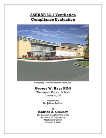
3.0 AHU DESIGN FEATURES3.1 DAIKIN D DM STANDARD FEATURES Variable dimensioning features for flexible cabinet sizing (increment 100mm in height and width)External Galvanized and internal painted cabinetPUR / PIR / Rockwool insulation panel materialMultiple section depthVariable coil casing and drain pan materialMixing boxesLow leakage damperDouble sloped drain panDifferent filter gradeVariable fan selection include forward-curved, backward curved and airfoil, AC/EC plug fanVariable frequency drive / Frequency inverter (VFD) and thermistorElectric heaterUltra Violet (UVGI)Energy Recovery Section ( Heat Recovery Wheel / Heat Pipe / Plated Heat Exchanger)Accessible and maintenanceFlexibility section for shipment3.2 CASING / CABINET CONSTRUCTIONDaikin DDM Air Handling Unit is designed in accordance BS EN 1886 and certified under EUROVENTCertification program (For DM2 and DM2TB). It is constructed of high strength extruded round edge aluminumpentapost and flat surface internal intermediate post with double modular skin insulation material. The framechannel design allows three identical pieces to be bolted together to form a composite corner piece. Both ofthis features form the rigid frame of the AHU. The unit wall is made up by Double Skin Polyurethane foam(PUR) insulation panel with 0.5 mm high strength pre-painted steel as external skin and 0.5 mm galvanizedsteel (GI) as internal skin. Besides, there are optional thicknesses: 0.8 / 1.0 / 1.2 /1.5mm of skin material. ThePU foam insulation thickness can be 25mm or 50mm with density 40 kg/m3.This cabinet construction reduces significantly the soundlevel from the fan of an AHU. The cabinet construction ismaintenance friendly through easy access to all components.The panels may be removed from all units sections withoutcompromising the unit rigidity which is ensured by thealuminum frame. The AHU Unit is designed to low energyconsumption and no condensation due to high thermalinsulation and airtight casings accordance to EN 1886.Figure 1: Round edge aluminum pentapostwith 3-legged injection Nylon corner piece.2
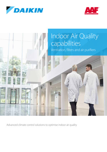
Access door or service panel can be supplied with a swingtype or removable panel type. Gasket around the fullperimeter of the access doors frame shall be used to preventair leakage. Module to module assembly shall beaccomplished with an overlapping splice joint that is sealedwith gasket on both mating modules to minimizeon-site labor along with meeting indoor airquality standards. Bolt and nut joining bracketprovide easier on-site combine of multiplemodule. The unit is mounted on galvanized steelbase frame for easy handling and positioning.Figure 2: Cabinet Appearance3.3 THERMAL BREAK PROFILEThis is a new and high quality thermal break round edge aluminum profile which can enhance performance ofan AHU. It is constructed of two parts of extruded aluminum joint together with thermal barrier nylon strip.The nylon is sandwiching the inner and outer layers of extruded aluminum. This design could render theformation of an effective isolated thermal layer between the inner and outer side of the profiles so that therelease of thermal energy via AHU could be ultimately minimized.The thermal bridging factor of the assembled DDM Air Handling Unit is designed to meet BS EN 1886, Class TB2.The thermal break profile only available for cabinet with 50mm thickness. A good AHU can be determined by:no air leakage and minimum heat loss through the AHU. The benefit of thermal break property showed asbelow increase the life of AHU and also save their operation cost for using long term. In addition, it is an idealdesign for high end performance.Benefit of Thermal Break ProfileNylon ThermalBreak Stripi) Increased Energy Efficiency –System energy efficiency is improved bylowering the heat loss.ii) Unit condensation minimized –Exterior condensation is potentiallydamaging or creating hazardous conditions.iii) Probability of moisture migration into panel interior, which candegrade the insulation, is eliminated in this thermal break profile.iv) Cut-off in an attempt to achieve energy conservation.v) Improve sound insulation.3
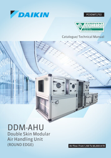
Daikin is well known with its superior quality. DDM AHU have also been recognized globally, including underthe Certification of EUROVENT and are leading-edge. Performance of DDM AHU and its mechanical strength,air leakage rate, cold bridge coefficient of the cabinet are tested.- Eurovent certification is renowned across the world for its highstandards and strict requirements on its air conditioner performance.Eurovents is call class-A certification in Europe. As a result, allEurovent-Certified products enjoy high credibility.- Eurovent standards for AHU products include EN1886 and EN13053.- EN1886 focuses on mechanical features of AHUs, including cabinetstrength level, cabinet leakage level, filter by-pass leakage, cabinetheat transfer coefficient, and cold bridge co-efficient.- EN13053 focuses on performance of the entire AHU, including actualair flow, air pressure, cooling capacity, heat capacity, motor powerand noises.DDM cabinet reachesEN1886 standardDM2TBCasingStrenghtCasing AirLeakageDM2D1(M) D1(M)L2Low GradeHi gh Gra deL2Class Classification of EN1886 standardStrenght classMaximum relative deformation ofthe cabinet under bearablepressure mm/mD1D2D3410 10Air leakage classMaximum air leakage rate of thecabinet under test pressure of -L1L2L30.150.441.32400 Pa (l/s/m2 )Maximum air leakage rate of thecabinet under test pressure of0.220.631.90 700 Pa (l/s/m2 )Filter ridgingFactorTB2Filter by-passed classF9F8F7F G1-F5Maximum by-pass leakage rate, kin % of the volume flow rate0.51246T1T2T3T4T5Thermal Transmitance classHeat transfer coefficient of thecabinet (U) W/(m2 .K)TB3Thermal bridging factor classCold Bridge coefficient of thecabinet (Kb)Table 14U 0.50.6 U 1.01.0 U 1.41.4 U 2.0NorequirementTB10.75 Kb 1.0TB20.6 Kb 0.75TB30.45 Kb 0.6TB40.3 Kb 0.45TB5Norequirement
3.4 COIL SECTIONCoil is installed such that unit casing enclose headers and return bends. Coil is designed based on themaximum utilization of available cross section area to achieve the most efficient heat transfer. Coilconnections should be factory sealed with grommets on interior and exterior and gasket sleeve between outerwall and liner where each pipe extends through the unit casing to minimize air leakage and condensationinside panel assembly. Coils shall be removable through side and/ or top panels of unit without the need toremove and disassemble the entire section from the unit.Coil constructed with aluminum corrugated fins and seamless copper tubes. Copper fins and hydrophilic finsare anti-corrosive materials which are optional. The fins are designed purposely for better heat transferefficiency and moisture carry-over limit performance. Capacity, water pressure drop and selection procedure isdesigned in accordance with ARI Standard 410.Cooling coils can be used when the face velocity does not exceed 2.5 m/s. For higher face velocity, a moistureeliminator is required to prevent condensate water carry over. For stacked coil in the coil section, drip pan isinstalled at back between coils to drain condensate to the main drain pans without flooding the lower coilsection. The optional intermediate drain pan can be supplied for those needs to access for cleaning betweenthe coils. Daikin Air Handling Units can handle both chilled water and direct expansion system.Figure 4: Water & DX System CoilFigure 5: Stacked Coil3.5 DRAIN PANThe deep and sloped drain pan is designed to discharge the condensate water quickly. It is fabricated bygalvanized steel sheet protected with powder coating paint or stainless steel as option. Beneath the drain pan,it is covered with 10mm PE insulation to prevent any occurrence of condensation. For stacked coil, additionaldrip pan or intermediate drain pan fabricated from same material as main drain pan will be installed at backbetween two coils.5
3.6 FACE AND BY PASS DAMPERIt consists of opposed blades varying air volume through the coil and by pass to attain the desired temperature.It provides very low leakage in the face and bypass sections. Face and bypass damper can be provided fortemperature modulation by bypassing air around the coil. The damper blades are fabricated of aluminum andcontinuous Thermoplastic Elastomer (TPE) seals are inserted onto every damper blade. The rotated rod ofhandle is made of brass and handle is fabricated of aluminum casting. The size of damper is decided by the airflow volume (m3/s) and air speed (m/s). The air speed go through the damper shall not exceed 7.5 m/s.3.7 FANFans are used extensively in air-conditioning for circulating air over coils. The fan type includes forward,backward, airfoil wheel fan, twin fans with double width double inlet (DWDI) centrifugal fan. The first low costoption will be forward curved fans which are generally used for low static pressure applications. The blade offan is constructed of galvanized steel. It consists of blade which has tips curving forward that is in the directionof rotation of fan wheel.Meanwhile, for backward curve fans, it is run at higher speed and thereforehas to be sturdier in construction. The blade of backward curved is made ofheavy gauge steel or mild steel, painted after manufacturing. It can handlehigh static pressure system and able to show higher efficiency over a broaderrange of higher system resistance.For airfoil fans, normally it will be the last option due to the costlycomponents. It is constructed of mild steel. However, it shows higherefficiency, generate low noise level and can handle higher static pressures.Daikin housed air foil fans can operate up to 2240pa of static pressure.Fan performance of all these fans have been tested and measured in accordance to AMCA Standard 210. Thesound level is measure and rated in accordance with AMCA Standard 300. The fan bearing provided will have aminimum L50 life of 200,000 hours, and option available as high as 1,000,000 hours. Bearings are selected forminimum noise level and minimal device. The bearing is lubricated for life and maintenance free, lubrication isoptional. Fan is dynamically and statically balanced to Standard ISO 1940. The fan shaft is manufactured fromC45 carbon steel. It is coated with a layer of anti-corrosion varnish.Fan discharges direction can be vertical (top & bottom) or horizontal discharge. The fan discharge should besquare (for both forward and backward wheel fans) in area and flanged and isolated from the casing by the fireretardant grade flexible connection. Only one fan discharge is provided.Fan selection requires accurate calculation of the air flow resistance through the whole system consisting ofthe total of two parts; external and internal static pressure. External static pressure is found in the distributionsystem, external to the air handler. Internal static pressure is the sum of the resistance of the coils and otherscomponent.Beside, a comprehensive range of AC & EC plug fans is available to meet different design criteria. These fansare design to operate unhoused inside the AHUs. The flexible fan section provides a wide combination ofdischarge arrangements. Plenum fans also contribute to lower overall system pressure drop, thereby reducingenergy consumption.6
Figure 6: AC plug fan & EC Plug Fan3.8 MOTORMotor is internally mounted integral to an isolated fan assembly. Standard motor shall be horizontal footmounting, induction motor, squirrel cage, totally enclosed fan-cooled (TEFC) with IP 55 protection and class Finsulation. Motor capacity cannot be undersized but oversized for desired running capacity. For the desiredoperation speed between fan and motor, different poles (2, 4, 6 and 8 poles) can be consider.MOTOR OPTION 380-415 Volt / 3 phase/ 50 Hz ( standard)230/380/440 Volt/ 3 phase/ 60HzMotor efficiency from IE1, IE2, IE3 up to IE4 (EC motor)Dual speed motorMotor with space heater & ThermistorExplosion / Flame proofFigure 7: Induction MotorThere are a few components which are able to provide safety, efficiency and flexibility feature for theoperation of AHU. It includes thermistor, variable frequency drives (VFD), disconnect switch and others. Whenoperating with VFD, frequency within 30 to 60 Hz is recommended for standard induction motor.3.9 FAN / MOTOR ASSEMBLIESFan assemblies are easy to service provided with – The adjustable motor bases allow for proper tensioning of thebelts at all times. Two-piece split belt guards The belt guard is fastened by bolt and nut via three clamps.Figure 8: Fan - Motor Assembly7
3.10 VIBRATION ISOLATORThe fan in AHU can create substantial vibration that will transform topanels/ casing and consequently widespread the generated sound waves.To avoid this, the spring or rubber isolator is mounted between the fancompartment and the rest of the AHU to prevent the transmission of noiseand vibration into panels.There are two types of isolators used: Rubber mounting ( for blower model 355) 25mm deflection spring ( for blower model 355)Figure 9. Vibration Isolator3.11 THERMISTORA thermistor is a type of resistor used to measure temperature changes in protection of windings in electricmotors.3.12 VFD/ FREQUENCY INVERTERA VFD provides adjustable speed control of a single fan motor. Normally, an AHU which has been installed byVFD can vary the frequency within 30 to 60 Hz in order to control the motor rotation speed. It also providesprotection for the motor operation.3.13 ENERGY RECOVERY3.13.1 HEAT RECOVERY WHEELIntroducing ventilation from outdoors is essential in maintaining desired indoor air quality. Heat wheel isavailable as the option to match this requirement. These energy components can recover 50% or more of theenergy normally exhausted from a building. They are working based on this concept – capture heat fromexhaust air as it passes through the air handling unit and transfer it to the supply air stream. Hence, it is able toreduce the cost of heating or cooling the outside air. During the winter, energy recovery components do thisby transferring energy from a warm air stream to a colder air stream. On the other hand, during the summer, itis used to cool the air hot air.It is constructed of aluminum coated with heat transfer material (silicagel or others) which is rotated by an electric motor at constant orvariable speed. It is currently known as the most efficient technology.There are two sections of fan required: exhaust fan and supply fan. Theheat wheel rotates at a constant low speeds, capturing andtransferring both sensible (heat) energy and latent (moisture) energy.The ability to transfer both sensible and latent energy gives the heatwheel several advantages. First, it can reduce the capacity ofventilation equipment. Furthermore, heat wheels can work at lowertemperature without frosting occurs. The supply air from the heatwheel is not near saturation level, and moisture in the ductwork is notan issue. The benefit includes recover both latent and sensible heat byallowing reduction in system capacity about 30 to 65%. The mostsignificant benefit is to prevent sick building syndrome.8Return AirExhaustAirSupplyAirFresh AirFigure 10: Heat Recover Wheel
3.13.2 HEAT PIPEHeat pipe technology was founded by president and inventor Khanh Dinh in year 1982. It is a simple devicethat can transfer heat quickly from one point to another without requisite of energy input. The basic make upof heat pipe is just a metal tube (usually copper) scaled at both ends, evacuated to a vacuum and charged withrefrigerant.When one end of the pipe is exposed to warm air stream, the inside refrigerant absorbs heat and evaporates(as shown in A) and the vapor moves to the cooler end (as shown in B). As the vapor reaches to the condensingarea of the cylinder (shown as C), the heat is given off to the environment and the vapor condenses. The liquidreturns by gravity or capillary action. This will be a continuous cycle inside the heat pipe.For conventional air conditioner, it uses up most cooling capacity to cool the air to dew point but less capacityfor dehumidification. Meanwhile, air conditioner which is installed with heat pipe enhance air conditionerusage by allowing more cooling capacity to go towards latent cooling by pre-cooling air before it gets tocooling coil session. Only periodical cleaning is required for maintenance.Figure 11: Heat Pipe (Wrap around Type & Straight Type)3.13.3 Air to Air cross flow Plated Heat Exchanger (PHE).Construct with corrugated aluminum fin to increase the turbulence andheat transfer without creating stagnation points, extruded aluminumcorner profiles and aluzinc steel endplate frame. Complete assemblyform a rigid, stable unit. Plate corners are sealed with MS polymersilicone free sealant and rated for air temperature up to 190 0F.Connecting plate edges are folded on automated manufacturingequipment. Adhesive in plate folds shall limit leakage to 0.1% at1.6”W.C. differential pressure. Air leakage is defined as 0.1% of therated airflow of the individual model.9Figure 12: Plated Heat Exchanger
3.14 HUMIDIFIERThere are two type of humidifiers are used commercially in AHU. First is electrode steam humidifier, which iscategorized isothermal type, the second, spray nozzle humidifier, which is adiabatic type. It requires an emptysection to be installed. It is a device which is used to increase the air humidity ratio in atmosphere withoutsteam source. It is a constant temperature humidifier. Its principle is the common electrode humidifierregulates the generated steam by the way of controlling water level and electrical current. Electrical loop willbe built up through salt minerals in the water. Therefore, water will be heated up and boiled until vapor isgenerated continuously. Quality of water in the region must be considered because it reduces the steamcapacity. (Softened water cannot be used).3.15 ELECTRIC HEATERIt is used to achieve desired room condition at certain desired relativehumidity. With negligible air pressure drop, accurate controllability,light weight, easy serviceability and inherent freeze protection,electrical heater is valuable alternatives to conventional steam andhot water heating coils.Electric heaters are optional with either single step or multi step ofheating process. It depends much on the heating capacity. Heaters areavailable in 220-230V and the wiring can be in single phase / 3 phasefor contactor or thyristor control.Figure 13. Electric Heater in AHU3.16 FILTER SECTIONIt plays a major role in maintaining good indoor air quality by filtration. There are a wide range of filter optionswhich are provided by prominent filter manufacturer. The DDM AHU has been designed to handle primary,secondary & HEPA filtration. Beside, activated carbon filters are available with designed to improve indoor airquality through the effective removal of indoor and outdoor gaseous contaminants typically found in the urbanenvironment. This includes VOCs, SOx, NOx, and Ozone.Figure 14. Wide range of industrial air filter10
3.17 Quick Air Filter Selection GuideClassification as per EN 779EN 779 ClassAverage Arrestance, Am%G1Am 65G265 Am 80G380 Am 90-AmerTex R15AmerTex R29Aluminum MeshRecommended FilterG490 AmAmAir 300EAmerTex R50Table 2: Filter Arrestance for Coarse filters in Class G1-G4EN 779 ClassAverage Efficiency, Em%Recommended FilterM5F6F7F8F940 Em 6060 Em 8080 Em 9090 Em 9595 EmDriPak 2000DriPak 2000Varicel IIVaricel IIDriPak 2000Varicel VXLAmAir 500EDriPak 2000Table 3: Filter Arrestance for fine filters in Class M5-F9Classification as per EN 1822EN 1822 ClassH 10H 11H 12H 13H 14 95 98 99.99 99.997 99.999Efficiency (% at MPPS) 85 95 99.5 99.95 99.995Recommended FilterBioCel I-AstroCel AstroCel AstroCel Table 4: Filter Efficiency for HEPA Filters Class H10-H14In addition, filter section can be enhanced by an optional item – filter pressure gauge to ensure regular filterservicing and prevent clogging. Normally, the filter life span can be indicated by pressure gauge value.3.18 MIXING BOX / DAMPERIt is an air inlet section to mix fresh and return air according to thesystem designer’s requirement. It can regulate the amount of outsideand return air supplied to the conditioned space. It consists of damperin parallel blades with opposed rotating blade with driving shaft. Thedamper blades are fabricated of aluminum and continuousThermoplastic Elastomer (TPE) seals are inserted onto every damperblade. The rotated rod of handle is made of brass and handle isfabricated of aluminum casting. There are a few type of arrangement:top, rear and combination of top and rear. The mixing box can make useof free cooling by opening outside air dampers when the ambient air willhelp to condition the supply air stream. In addition, dampers maybeindividually sized to provide better mixing effect.Figure 15. Damper & Mixing Box11
3.19 SOUND ATTENUATORIt has a perimeter galvanized steel frame. Standard pods issupplied 100mm thick in standard lengths of 900 and1200mm according to the attenuation required. Themodular widths available are 275mm or 300mm.Nowadays, sound level will be an essential factor to beconsidered as one of the performance of units. Daikinproduct has been designing to provide the quietest soundlevel. Different attenuator length can be selected to meetthe most stringent sound attenuation requirements. Acomfortable surrounding enhances human’s working andliving life.Figure 16. A Typical Cut Away View of soundattenuator3.20 ULTRA VIOLET GERMICIDAL IRRADIATION (UVGI)Figure 17. ULTRA VIOLETAir Handling Unit Systems shall include Ultraviolet Emitters foreradicating germs harboring in cooling coils and drain pans.Ultraviolet Germicidal Irradiation (UVGI) Lamps shall beinstalled after the cooling coil and before the fan section, whichis the dampest area and is most prone to microbial growth.This is to eliminate the growth of surface microbialcontainments on coils, fins and drain pans.UVGI Systems is constructed with an inner lamp made of softglass and out shell made of Quartz glass (called Quartz Shield)There are 3 main concern for greater kill rate for microbialcontainment, which are :1. Time : The greater the exposure time (contact time between the contaminant & the UV source), themore UV energy can be delivered to the contaminant resulting in a greater Kill Rate.2. Intensity: The greater the intensity (strength of the UV source), the more UV energy can be deliveredto the contaminant resulting in a greater Kill Rate.3. Distance: A “distance correction factor” may be needed when calculating a desired dose or intensity toa surface.12
4.0 STANDARD UNITS QUICK SELECTION TABLETable 5 : Return AirUNIT4-ROWS COOLING COILWaterT.C.COff Coil ( 45/19.2230.45/19.222.15
The air flow of DDM AHU is within range of 330 to 20,000 lps (700 to 42379 CFM) and up to a total static pressure of 2000 pa (8" W.G). For special design, the air flow can be reached 25,000 lps (52974 CFM). The AHU is constructed of high strength extruded Aluminum to form rigid frame. Besides, it is with thermal