Transcription
0044 DeVilbiss SmartLink Module Instruction Guide,EN ModelDV5MCAUTION–Federal (U.S.A.) law restricts this device to sale by or on the order of a physician.uía de instrucciones del módulo SmartLink de DeVilbiss ,ES Gmodel DV5MPRECAUCIÓN: La legislación federal de los EE. UU. restringe la venta de este dispositivo a médicos o porprescripción médica.Manuel d’utilisation du module SmartLink DeVilbiss , modèleFR DV5MATTENTION – En vertu de la loi fédérale américaine, cet appareil ne peut être vendu que par un médecin ousur ordonnance de ce dernier.edienungsanleitung für das DeVilbiss SmartLink -Modul,de BModell DV5MACHTUNG – Laut US-Bundesgesetz darf dieses Gerät nur von einem Arzt bzw. auf Anordnung eines Arztesverkauft werden. Guida all'utilizzo del modulo DeVilbiss SmartLink , Modelloit DV5MATTENZIONE – La legge federale statunitense limita la vendita di questo dispositivo ai medici o su loroprescrizione.nstructiehandboekje voor DeVilbiss SmartLink module, modelnl I DV5MATTENTIE– De federale wetgeving in de Verenigde Staten schrijft voor dat dit apparaat uitsluitend magworden verkocht of voorgeschreven door een arts.
12453English. EN - 3Español. ES - 14Français. FR - 26Deutsch. DE - 38Italiano. IT - 50Nederlands. NL - 61EN - 2A-DV5M-1
TABLE OF CONTENTSIntroduction.Symbol Definitions.Important Safeguards.Set Up.Important Parts of Your SmartLink Module.Connection to the CPAP.Optional Oximeter Connection.Operating Instructions.Navigating Menus and Onboard Reporting.Data Retrieval.Accessories.Cleaning Instructions.Service ce and Manufacturer’s Declaration.EN - 3EN - 4EN - 4EN - 5EN - 5EN - 5EN - 6EN - 6EN - 6EN - 7EN - 8EN - 8EN - 8EN - 9EN - 10EN - 10INTRODUCTIONThe DeVilbiss SmartLink Module is an optional accessory to the DV5X series CPAP devices. This SmartLinkdevice was supplied to you by your homecare provider as part of your overall positive airway pressure therapyfor obstructive sleep apnea (OSA). SmartLink is a helpful tool for your physician and/or homecare providerbecause it allows them to see the effectiveness of the therapy and how frequently and consistently you usethe device.The information SmartLink collects helps bring to light potential problems or challenges you are facing thatyour clinician might be able to help you with in getting used to therapy.SmartLink is an advanced technology module that works together with your CPAP (Continuous Positive AirwayPressure) device.This system is unique in healthcare because many times a clinician will prescribe a therapy and send youhome with it and never really know how effective it is. SmartLink is a great benefit to you because it helps yourclinician keep track of what’s going on with your condition without you having to make extra trips to theclinician’s office.Indications For UseThe DeVilbiss SmartLink System can only be used in conjunction with the DV51, DV53, DV54, DV55, DV56,and DV57 Series CPAP Systems for follow up of obstructive sleep apnea in patients weighing above 30 kg onnasal CPAP therapy.A-DV5M-1EN - 3
SYMBOL DEFINITIONSAttention - Consult Instruction GuideData Port Input/OutputType BF equipment– applied part Memory Card Insertion Orientation lass II electrical protection– doubleCinsulatedOximeter Connection PortThis device contains electrical and/or electronic equipment that must be recycled per ECDirective 2002/96/EC- Waste Electrical and Electronic Equipment (WEEE)IMPORTANT SAFEGUARDSPlease read all instructions carefully before use. Important information is highlighted by the following terms:DANGERUrgent safety information for hazards that will cause serious injury or death.WARNINGImportant safety information for hazards that might cause serious injury.CAUTIONInformation for preventing damage to the product.NOTEInformation to which you should pay special attention.DANGER Electric Shock Hazard-Do not use while bathing. Electric Shock Hazard-Do not immerse this device into water or any other liquid. Electric Shock Hazard-Do not attempt to open or remove the enclosure. There are no userserviceable components inside. Contact your home care provider if your device needs servicing.Opening or tampering with the product will void the warranty.WARNING Use the SmartLink Module only for its intended use as described in this manual. Be sure to read and understand all safety instructions supplied with your SmartLink Moduledevice. Use only accessories recommended by DeVilbiss. Use only data cards provided by your homecare provider. Other Secure Digital (SD) cards may notbe compatible with the system or may not perform properly. Do not expose the device to water. If water has been spilled onto the SmartLink Module or it has been submerged into water, unplugthe power cord from the power source. Allow the device to completely dry before use. If the device has been dropped, refer to the troubleshooting guide for instructions. Contact yourhome care provider for evaluation of the device. To avoid electric shock, always unplug power cord from wall outlet power source whenperforming cleaning. Do not insert any foreign objects into any openings.EN - 4A-DV5M-1
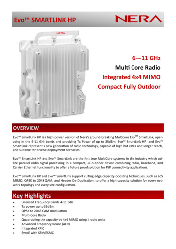
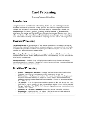
CAUTION–The circular data port and oximeter connectors located on the side of the SmartLink Module areused to attach accessories to the device. The connectors must only be used with accessories approved foruse by DeVilbiss. Do not attempt to attach any other device to these connectors as it may damage the CPAP,SmartLink Module, and/or the device you are attempting to attach.Be sure that you read and understand the information in this instruction guide. The information in this guidewill help you understand the operation of the Smartlink Module and how to properly maintain it. By followingthese instructions and the advice of your physician, your SmartLink Module will become an effective additionto your CPAP therapy.SAVE THESE INSTRUCTIONSSET UPImportant Parts Of Your SmartLink Module1.Data card slot2.Release button3.Secondary accessory data connection port4.Oximeter connection port5.Primary data connector6.Locking tabs (3 tabs)7.Instruction Guide (not shown)A12 3 4Connection To The CPAP3 42BNote–Your CPAP may already have been provided to you with the SmartLinkattached. If you have received your module separately from the CPAP, follow the6steps below to properly attach the module to the CPAP.1. Locate the primary data connector on the back of the SmartLink Module.Align and engage the primary data connector into the circular DINconnector on the back of the CPAP. At the same time, align and engagethe three locking tabs on the module with the three locking recesses on65 6the back surface of the CPAP Figure 1.2. Firmly press the module onto the back of the CPAP until the module isfully secured and locked into position Figure 2. An audible click may beheard confirming that the module is properly attached to the CPAP. Visually confirm that there is not agap between the module and the CPAP.Removal From The CPAPTo remove the module from the CPAP:1. Fully depress the release button on the side of the module.2. Pull the module straight back and away from the CPAP.CAUTION- Do not pull up on the module as this may damage the data connector.A-DV5M-1EN - 5
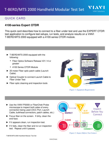
Optional Oximeter ConnectionThe SmartLink Module provides oximeter connection capability to allow an approved Nonin XPOD oximeter tobe used with the CPAP/module system. Connect the oximeter cable into the oximeter connection port locatedon the side of the module. If you are using an oximeter, please refer to the assembly and operationinstructions that came with the oximeter Figure 3.You can see your oximeter readings by using the SmartLink menu (see SmartLink Menu Structure) at anytime.Message shown when the oximeter is first connected and logging starts. This OximeterConnectedmessage will remain on display for five seconds. The pulse oximeter menu(SpO2/PR) will then be displayed.Message shown when the oximeter is removed. This message will remain on OximeterRemoveddisplay for five seconds. Multiple notifications will occur until logging stops.SmartLink Menu StructureTo display or remove SmartLink menu, press Left and Right Arrow Keys together. Use Arrows to navigatethrough the menu structure as shown (will follow dotted line).Navigation: Right Arrow - navigates right through menu items. Left Arrow - navigates left through menu items. Up Arrow - navigates up through menu items. Down Arrow - navigates down through menu items.To Exit SmartLink menu (choose one):1. Turn blower on or off2. Press Left and Right Arrow Keys together.SmartLink MenuPress To ExitVolume100% (Adjust )Serial NumberCM123456Firmware VersionV0.06 25/04/2008SPO2PR:100101Operating InstructionsNavigating Menus and Onboard ReportingWhile the SmartLink Module is attached, it will collect important data about how the device is being used andwhat kind of therapy it is delivering for you. Much of the information that is collected is available to you throughthe onboard menu on your CPAP display. The previous table shows how to navigate through the menus.When the SmartLink is connected correctly, the display on the CPAP willSmartLink Moduleshow this message. Note–if a data card is inserted in the module beforeReady for Useattaching the module to the CPAP, then card detection messages may bedisplayed.To enter the SmartLink menu, press the LEFT and RIGHT Arrow keys on the SmartLink MenuCPAP keypad at the same time. To exit the SmartLink menu, press the same Press To Exitkey sequence again or simply turn the CPAP off and on.Press the UP or DOWN arrow key on the CPAP keypad to adjust the volume Volume100% (Adjust )for the audible alert notification.EN - 6A-DV5M-1
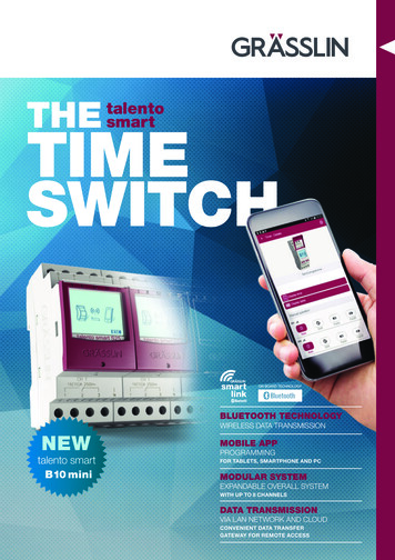
This menu displays the serial number of the SmartLink module connected tothe CPAP.This menu displays the operating firmware version of the SmartLink moduleconnected to the CPAP.This menu displays the pulse oximetry (SpO2) and pulse rate (PR) informationwhen a pulse oximeter is used with the system. If a pulse oximeter is notconnected to the module “***” will be displayed for the SpO2 and PR values.Serial NumberCM123456Firmware VersionV0.06 25/04/2008SpO2:PR:100101Data RetrievalYour clinician may have a standard protocol to follow-up on your therapy to find out how the device is workingand to identify any problems or issues you may be having. Your home care provider will mail a SmartLink DataCard to you at certain intervals and ask you to download the data onto the card and mail it back. It is a verysimple process:1. Ensure that the SmartLink module is properly connected to the CPAP and that the CPAP is connected toan appropriate power source.2. Orient that card as shown in Figure 4. Insert and press the card into the card slot located on the top ofthe module until the card clicks into place Figure 5.3. Ensure that the card is detected (view message or audible alert) and allow the data to transfer to thecard. Depending on the amount of data, this could take several minutes. Do not remove the card fromthe module until complete. Observe the message(s) on the display to confirm that the transfer wassuccessful (see Messages below). If necessary, contact your provider and report any errors that mayhave occurred.4. If instructed by your provider, eject the card from the card slot by pressing down on the card until it isreleased and remove the card from the slot.5. Place the card in the provided mailer and return it to the provider.MessagesThe following messages could be displayed on the CPAP during the data retrieval process:Message shown when a card is first inserted into the SmartLink Module andCard Detecteddata is being transferred. This message will remainPlease Wait . . .on the display until transfer is completed.Message shown when a card is first inserted into SmartLink Module and there Card DetectedReady For Useis no new data to transfer. Will remain on display for ten seconds.Message shown after completion of card data transfer. This message willremain on the display for ten seconds.Card TransferSuccessfulMessage shown if an error is encountered during card data transfer. ThisCard Errormessage will remain on the display until acknowledged by pressing any key on Contact Providerthe keypad or a 15 minute timeout occurs.Message shown if an error is encountered while updating device settings. This Setting Errormessage will remain on the display until acknowledged by pressing any key on Contact Providerthe keypad or a 15 minute timeout occurs. NOTE–If this message is displayed,contact your clinician.A-DV5M-1EN - 7
Message shown after removing the card from the module. This message willremain on the display for ten seconds.Card RemovedSend to ProviderMessage shown when a new module with mismatched data is detected.Setup RequiredThis message will remain on the display until the module is removed.Contact ProviderContact your provider to notify them of the situation and for instructions onhow to resolve the issue. If this situation is not resolved, the module will notbe able to record usage and therapy data. However, although this messagewill remain on the display with the module attached, the CPAP will still be functional and provide therapy.Other MessagesIn the unlikely event that a fault should occur, this message will be shownwhen a module fault condition is encountered (Clock Error, Memory Error,Setting Error, etc).Message shown when firmware is being updated. This message will remainon the display until the update is complete. Occasionally a firmware updatemay be provided for your device via SmartLink Data Card. The firmwareupdate process is automatic and may take a few seconds to complete. Oncethe update is complete, the system will return to normal operation.E00 Module FaultContact ProviderFirmware UpdatePlease Wait . . .ACCESSORIESOximeter Kit. DV5M-697Oximeter Finger Clip Sensor. 8000AAOximeter Ear Clip Sensor.8000QOximeter Finger Soft Sensor, Medium. 8000SMOximeter Finger Soft Sensor, Large. 8000SLCLEANING INSTRUCTIONSwarningTo avoid electric shock, always unplug power cord from the wall outlet power source.CAUTION-Never rinse or place the device in water. Never allow liquids to get into or around any of the portsor openings; doing so will result in product damage. If this occurs, do not use the device. Contact your providerfor service.NOTE–The module should be cleaned as needed.1. Turn off the CPAP and unplug it from the power source.2. Use a soft damp cloth to clean the surfaces of the device.3. Allow the device to dry completely before plugging it into a power source.SERVICE INSTRUCTIONSThe SmartLink Module does not require regular servicing.EN - 8A-DV5M-1
TROUBLESHOOTINGProblemProbable CauseRemedyModule is notrecognized whenconnected to theCPAP.1. T he CPAP is notconnected to a powersource.2. Module is not fullyattached to the CPAP.1. C onnect the CPAP to an appropriate power sourceand verify that the module is recognized.Card notrecognized wheninserted into themodule card slot.1. Card not orientedproperly.1. R efer to the symbol on the top of the module orFigure 4 in this guide for proper card orientation.2. Card not fully inserted inthe module card slot.3. Module is not fullyattached to the CPAP.Card error.1. Wrong card type.2. P ress the card fully into the card slot until the cardclicks into position.3. R emove the module from the CPAP, realign theprimary data connector with the circular DINconnector of CPAP, and press firmly until the moduleis locked into position. Be sure there is not a gapbetween the module and the CPAP.1. O nly use a card supplied by your provider. The cardmust be an SD card with FAT16 format.2. C ard must not be removed during data transfer. Datatransfer interruption may corrupt the card andprevent the card from working correctly. Reinsertcard and allow data transfer to continue untilcompleted.3. R eturn card to provider for replacement.2. Card removed duringdata transfer.3. Card corrupt or faulty.Settings error.1. Card removed duringdata transfer.2. Card corrupt or faulty.Setup required.Oximeter data(SpO2 and PR) notdisplayed.A-DV5M-12. R emove the module from the CPAP, realign theprimary data connector with the circular DINconnector of CPAP, and press firmly until the moduleis locked into position. Be sure there is not a gapbetween the module and the CPAP.1. C ard must not be removed during data transfer. Datatransfer interruption may corrupt the card andprevent the card from working correctly. Reinsertcard and allow data transfer to continue untilcompleted. If this error is not corrected, contactprovider for resolution.2. R eturn card to provider for replacement. If this erroris not corrected, contact provider for resolution.1. N otify provider of the situation and follow providerinstructions.1. V erify connection between the oximeter connectorand module oximeter connection port.1. Module not set upproperly.1. Oximeter not properlyconnected to theSmartLink module.2. Oximeter probe not2. R eference the operating instructions that came withproperly attached to user.oximeter.EN - 9
ProblemProbable CauseCPAP is not fullyfunctional.1. Module may be defective. 1. R emove the module from the CPAP and verify thatCPAP is fully functional. If it functions properlywithout the module connected, the module may bedefective. Contact provider. If it still is not fullyfunctional, consult the CPAP instruction guide fortroubleshooting.RemedyDeVilbiss SmartLink SpecificationsSize: . . . . . . . . . . . . . . . . . . . . . . . . . . . . . . . . . . . . . . . 3.9” H x 3.1” W x 1.4” D (9.9cm H x 7.9cm W x 3.6cm D)Weight: . . . . . . . . . . . . . . . . . . . . . . . . . . . . . . . . . . . . . . . . . . . . . . . . . . . . . . . . . . . . . . . . . . . 0.30 lbs. (0.14 Kg)Electrical Rating:Maximum Power Consumption (SmartLink Module only): . . . . . . . . . . . . . . . . . . . . . . . . . . . . . . . . . . . . . . . 4 WVoltage and Current: . . . . . . . . . . . . . . . . . . . . . . . . . . . . . . . . . . . . . Power supplied by the DV5X Series DeviceClass II Equipment; Type BF Applied Parts; Continuous OperationOperating Conditions:Temperature Range: . . . . . . . . . . . . . . . . . . . . . . . . . . . . . . . . . . . . . . . . . . . . . . . . 41 F to 104 F (5 C to 40 C)Humidity Range: . . . . . . . . . . . . . . . . . . . . . . . . . . . . . . . . . . . . . . . . . . . . . . . . . . 0 to 95% R.H. non-condensingAtmospheric Conditions: . . . . . . . . . . . . . . . . . . . . . . . . . . . . . . . . . . . . . . . . . . . . . Sea level to 9,000’ (2,743 M)Transportation and Storage Conditions:Temperature Range: . . . . . . . . . . . . . . . . . . . . . . . . . . . . . . . . . . . . . . . . . . . . . -40 F to 158 F (-40 C to 70 C)Humidity Range: . . . . . . . . . . . . . . . . . . . . . . . . . . . . . . . . . . . . . . . . . . . . . . . . . . 0 to 95% R.H. non-condensingDeVilbiss guiDance anD manufacturer’s DeclarationWARNINGMedical Electrical Equipment needs special precautions regarding EMC and needs to be installed andput into service according to the Electromagnetic Compatibility [EMC] information provided in theaccompanying documents.Portable and Mobile RF Communications Equipment can affect Medical Electrical Equipment.The equipment or system should not be used adjacent to or stacked with other equipment and that ifadjacent or stacked use is necessary, the equipment or system should be observed to verify normaloperation in the configuration in which it will be used.NOTE– The EMC tables and other guidelines provide information to the customer or user that is essential indetermining the suitability of the Equipment or System for the Electromagnetic Environment of use, and inmanaging the Electromagnetic Environment of use to permit the Equipment or System to perform its intendeduse without disturbing other Equipment and Systems or non-medical electrical equipment.EN - 10A-DV5M-1
Guidance and Manufacturer’s Declaration – Emissions All Equipment andSystemsThis device is intended for use in the electromagnetic environment specified below. The customer or user ofthis device should assure that it is used in such an environment.Emissions TestComplianceRF EmissionsCISPR 11Group 1RF EmissionsCISPR 11Class BRadiated andConducted EmissionsHarmonicsIEC 61000-3-2Class AFlickerIEC 61000-3-3CompliesElectromagnetic Enforcement – GuidanceThis device uses RF energy only for its internal function.Therefore, its RF emissions are very low and are not likelyto cause any interference in nearby electronic equipment.This device is suitable for use in all establishments includingdomestic, and those directly connected to the public lowvoltage power supply network that supplies buildings usedfor domestic purposes.IEC 60601 TestLevelCompliance LevelElectrostaticDischarge (ESD)IEC 61000-4-2 6kV contact 8kV air 6kV contact 8kV airFloors should be wood, concrete orceramic tile. If floors are synthetic,the relative humidity should be atleast 30%.Electrical FastTransient/burstIEC 61000-4-4 2kV on AC Mains 2kV on AC MainsMains power quality should be that ofa typical commercial or hospitalenvironment.SurgeIEC 61000-4-5 1kV Differential 2kV Common 1kV Differential 2kV CommonMains power quality should be that ofa typical commercial or hospitalenvironment.Voltage dips, shortinterruptions andvoltage variationson power supplyinput linesIEC 61000-4-11 95% Dip for0.5 Cycle60% Dip for5 Cycles30% Dip for25 Cycles 95% Dip for5 Seconds 95% Dip for0.5 Cycle60% Dip for5 Cycles30% Dip for25 Cycles 95% Dip for5 SecondsMains power quality should be that ofa typical commercial or hospitalenvironment. If the user of this devicerequires continued operation duringpower mains interruptions, it isrecommended that the device bepowered from an uninterruptiblepower supply or battery.Immunity TestA-DV5M-1Electromagnetic Environment GuidanceEN - 11
Immunity TestPower Frequency50/60Hz MagneticFieldIEC 61000-4-8Conducted RFIEC 61000-4-6IEC 60601 TestLevelCompliance Level3A/m3A/m3 Vrms from150 kHz to 80 MHzV1 3 VrmsElectromagnetic Environment GuidancePower frequency magnetic fieldsshould be that of a typical location ina typical commercial or hospitalenvironment.Portable and mobile RFcommunications equipment should beseparated from the device by no lessthan the recommended separationdistances calculated/listed below:D (3.5/V1) PRadiated RFIEC 61000-4-33 V/m80 MHz to 2.5 GHzE1 3V/mD (3.5/E1) P 80 to 800 MHzD (7/E1) P800 MHz to 2.5 GHzWhere P is the maximum powerrating in watts and D is therecommended separation distance inmeters.Field strengths from fixedtransmitters, as determined by anelectromagnetic site survey, shouldbe less than the compliance levels(V1 and E1).Interference may occur in the vicinityof equipment containing a transmitter.For transmitters rated at a maximum output power not listed above, the recommended separation distanceD in meters (m) can be estimated using the equation applicable to the frequency of the transmitter, where Pis the maximum output power rating of the transmitter in watts (W) according to the transmittermanufacturer.Note 1: At 80 MHz and 800 MHz, the separation distance for the higher frequency range applies.Note 2: These guidelines may not apply in all situations. Electromagnetic propagation is affected byabsorption and reflection from structures, objects, and people.EN - 12A-DV5M-1
Recommended Separation Distances Between Portable and Mobile RFCommunications Equipment and this device. This device and systemare NOT Life-SupportingThis device is intended for use in the electromagnetic environment in which radiated disturbances arecontrolled. The customer or user of this device can help prevent electromagnetic interference bymaintaining a minimum distance between portable and mobile RF Communications Equipment and thedevice as recommended below, according to the maximum output power of the communications equipment.Maximum OutputPower (Watts)Recommended Separation Distances for the device (meters)150 kHz to 80 MHz80 to 800MHz800 MHz to 2.5 GHzD (1.1667) PD (1.1667) PD (2.3333) .66723.333For transmitters rated at a maximum output power not listed above, the recommended separation distanceD in meters (m) can be estimated using the equation applicable to the frequency of the transmitter, where Pis the maximum output power rating of the transmitter in watts (W) according to the transmittermanufacturer.Note 1: At 80 MHz and 800 MHz, the separation distance for the higher frequency range applies.Note 2: These guidelines may not apply in all situations. Electromagnetic propagation is affected byabsorption and reflection from structures, objects, and people.A-DV5M-1EN - 13
ÍndiceIntroducción.Definiciones de símbolos.Precauciones importantes.Preparación .Piezas importantes del módulo SmartLink.Conexión al dispositivo de CPAP .Conexión al oxímetro opcional.Instrucciones de uso .Menús de desplazamiento e información en la pantalla .Recuperación de datos.Accesorios.Instrucciones de limpieza.Instrucciones de mantenimiento.Resolución de problemas.Especificaciones.
When the SmartLink is connected correctly, the display on the CPAP will show this message. NOTE-if a data card is inserted in the module before attaching the module to the CPAP, then card detection messages may be displayed. To enter the SmartLink menu, press the LEFT and RIGHT Arrow keys on the CPAP keypad at the same time.