Transcription
9111 Jackrabbit Road,Houston, Texas 77095Tel: 281-856-1300Fax: 281-856-1325www.emcowheaton.comINSTALLATION, OPERATION &MAINTENANCE MANUALEMCO WHEATONTop & BottomLoading ArmsThe content of this paper is the intellectual property of EMCO WHEATON USA. Reproduction - also of extracts - is not permitted. Likewise, they must not in any way be made accessible to third parties, in particular competitors.This manual contains information that may not pertain to your arm.Rev.: 1
Instruction ManualTop & Bottom Loading ArmsE2110, E2112, E2022, E2025E2033, E2304, E2573, E2123,E2313, E2121Table of Contents1 Safety.11.1 Safety Comments.11.2 Safety Symbols and Notes .22 Loading Arm Types .23 Loading Arm Description.33.1 Loading Arm.33.2 Main Components - Top Loading .33.3 Survey Drawing .43.4 Main Components - Bottom Loading .53.5 Survey Drawing .54 Warranty .65 Delivery and Storage .66 Installation.76.1 Installation of the Loading Arm .76.2 Installation of Feed Lines .97 Commissioning.98 Operation of the Loading Arm.108.1 Operation of Loading Arms with Open B-Length .108.2 Operation of the Loading Arms with Flange/Coupler.119 Service and Maintenance.119.1 Safety Comments.119.2 Spare Parts .129.3 Regular Tests .129.4 General Maintenance .129.5 Service Intervals.139.6 Lubrication Points at the Loading Arm.139.7 Maintenance of Swivel Joints .149.7.1 Maintenance of D2000 Swivel Joints.159.8 Spring Cylinder Maintenance .159.9 Spring Cylinder Adjustment . . 169.10 Replacement and Disposal of Spring Cylinder .169.11 Bolt Connections .169.12 Painting .169.13 Hose.169.14 Couplers.179.15 Electrical Equipment.179.16 E0471 Loading Valve . .179.17 Other Valve types .19Rev.: 1
Instruction ManualTop & Bottom Loading ArmsE2110, E2112, E2022, E2025E2033, E2304, E2573, E2123,E2313, E21211 Safety1.1 Safety CommentsThe following instruction manual describes the loading arm delivered by EMCOWHEATON. It does not describe the loading system and does not include fittingsand devices which are not part of the loading arm.This manual explains how to install, operate and maintain the loading arm,helping to ensure safety and functionality.Follow the instructions of this manual in all details. It does not release you fromthe responsibility to perform the described steps in a professional and appropriatemanner.Please refer to all drawings and additional documentation accompanying thismanual for important data pertaining to the loading arm.The loading arm is intended to be assembled in a loading system. It must not beused prior to the loading system being confirmed to correspond to the currentversion of all local laws, regulations and requirements which apply. This manualdoes not replace these rules in any way.EMCO WHEATON offers on-site training for installation and maintenance ofsupplied equipment.Intended UseEMCO WHEATON Loading Arms are movable pipes and joints for transferringfluid between a fixed connection and a movable tank. Refer to the loading armgeneral arrangement drawings for information about the conditions for using theloading arm.Any other use of the loading arm is not intended and therefore not permitted. Do not change the structure of the loading arm in any way. Any changes mayendanger persons and/or cause the loading arm to become unsafe. ContactEMCO WHEATON for information. Do not use the loading arm when you notice it has been damaged or ismalfunctioning. Contact your supervisor immediately. Only change the operating conditions of the loading arm with written permission byEMCO WHEATON. The loading arm has been designed for the conditions describedin the drawings accompanying this documentation. Contact EMCO WHEATON forauthorization if the loading arm is required to exceed the conditions specified, toensure that the loading arm meets the new requirements. Follow the instructions and warnings on the loading arm. Do not cover or remove any signs on the loading arm.The customer shall only allow staff working with the loading arm that: are capable of safely handling the loading arm; have been trained on proper handling the loading arm; Understand the dangers of the loading arm.-1-
Instruction ManualTop & Bottom Loading ArmsE2110, E2112, E2022, E2025E2033, E2304, E2573, E2123,E2313, E21211.2 Safety Symbols and NotesThis instruction manual also indicates potential dangers of handling, operating andmaintaining loading arm. These dangers are highlighted in the text with an explanationof how to avoid them. Observe the highlighted cautionary notes and be especiallycareful in these situations. Explain these dangers to all persons working with or nearthe loading arm.DangerThis symbol indicates a hazardoussituation which will result in serious injuryor death, if not avoided.AttentionThis symbol indicates a hazardoussituation which could result in seriousinjury or death, if not avoided.CautionThis symbol indicates a hazardoussituation which may result in minor ormoderate injury, if not avoided.NoteThis symbol indicates additionalinformation and imposes no hazardoussituation.2 Loading Arm TypesRefer to the drawings, parts lists and accompanying documentation for additionalinformation specific to your loading arm.AttentionOperating the loading arm outside ofthe specified conditions may damagethe loading arm which could result inserious injury or death.The loading arm has been designedfor the operating conditions shown onthe general arrangement drawings.Please refer to the drawings andensure the arm is operated within thespecified limits.-2-
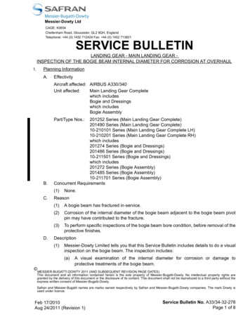
Instruction ManualTop & Bottom Loading ArmsE2110, E2112, E2022, E2025E2033, E2304, E2573, E2123,E2313, E21213 Loading Arm Description3.1 Loading ArmThe EMCO WHEATON Loading Arms are a movable pipe system for loading orunloading railroad cars, tank trucks and other vessels. The transfer of fluid isachieved by either introducing the loading arm into the manhole or making aconnection to the flange of the vessel. Please refer to the general arrangementdrawing for connection details.EMCO WHEATON Swivel Joints and counterbalance mechanisms providesmooth and balanced movement of the loading arm in all directions. EMCOWHEATON loading arms are also designed to be self-supporting.3.2 Main Components - Top LoadingRefer to Figure 1 and 2 in Section 3.31.The F-Length provides reach in the horizontal plane. (boom style armsonly)2.The A-Length provides reach in the horizontal and vertical planes.3.The B-Length is introduced into or connected to the tank or vessel.4.Swivel joints connect piping and elbows allowing the loading arm toarticulate while maintaining a pressure tight seal.5.The spring cylinder balances the A-length and provides assistedmovement of the loading arm.6.The vacuum breaker introduces air into the arm and facilitates drainingof the loading arm.7.Handles are supplied to aid in manipulation of the loading arm.8.The loading valve is used to start and stop the product flow. EMCOWHEATON loading valves feature an adjustable slow closing mechanismto control the rate of closure to prevent line shock.9.Other valve types are used to start and stop the product flow of loadingarms for chemical, hot & food products.10.A remote control is used to assist in operating the loading valve whilethe operator is visually monitoring the fluid level.11.The flange or coupler is used to connect the loading arm to thecorresponding connector on the vessel.12.A proximity switch (limit switch) can be installed to monitor the positionof the loading arm or the state of the product valve (open/closed).-3-
Instruction ManualTop & Bottom Loading ArmsE2110, E2112, E2022, E2025E2033, E2304, E2573, E2123,E2313, E21213.3 Survey Drawing (Model E2025 shown)Figure 1Figure 2-4-
Instruction ManualTop & Bottom Loading ArmsE2110, E2112, E2022, E2025E2033, E2304, E2573, E2123,E2313, E21213.4 Main Components – Bottom LoadingRefer to Figures 3 and 4 in Section 3.51.The stand post carries the loading arm. If several loading arms arestanding in a row, the stand post of each loading arm has a different heightto enable you to cross the hoses without collision.2.The intermediate tube carries the parking device.3.The F-Length provides reach in the horizontal range.4.The A-Length provides reach in the horizontal and vertical range.5.The B-Length is connected to the tank or vessel.6.Swivel joints connect piping and elbows allowing the loading arm toarticulate while maintaining a pressure tight seal.7.The spring cylinder balances the A-length and provides assistedmovement of the loading arm.8.The vent connection is used to vent the loader while filling it with productor to accelerate draining for maintenance.9.Use the handle to move the loading arm.10.The coupler of the loading arm connects to the adapter at the tank orvessel.3.5 Survey Drawing (Model E2304 shown)Figure 3-5-
Instruction ManualTop & Bottom Loading ArmsE2110, E2112, E2022, E2025E2033, E2304, E2573, E2123,E2313, E2121Figure 44 WarrantyEMCO WHEATON grants a warranty for the loading arm. Refer to your orderconfirmation or the EMCO WHEATON Terms and Conditions.Items NOT covered under warranty are: Damage caused by inappropriate handling and storage Damage caused by faulty installation Damage caused by incorrect adjustment Components with removed or illegible labelling Damage caused by incorrect operation Worn parts5 Delivery and StorageAll EMCO WHEATON products are secured and packed carefully at the factory.Although the utmost care has been taken in preparing the loading arm forshipment, please inspect for transport damages and completeness on receipt ofgoods. Notify EMCO WHEATON about any findings or concerns immediately.Claims submitted on a later date cannot be accepted.Store the goods in a sheltered area as soon as the delivery is received and coverthem properly to protect them from dirt and moisture. Provide ventilation to avoidcorrosion caused by condensation.-6-
Instruction ManualTop & Bottom Loading ArmsE2110, E2112, E2022, E2025E2033, E2304, E2573, E2123,E2313, E2121For loading arms not supplied with a finish coating, the customer is responsiblefor painting the arm to provide corrosion protection.Protect all hoses and cables against rodents. If the arm is to be stored for anextended period, protect with a suitable preservative. Please contact EMCOWHEATON for more information.6 Installation6.1 Installation of the Loading Arm (E2025 & E2304 shown)Attach suitable hoisting gear to the loading arm for lifting the loading arm and toavoid damaging the loading arm.DangerDuring installation of the loadingarm it could turn or fall downKeep a safe distance from theloading arm while hoistingLoosen the transportation locks and remove all packing material. Lift the loadingarm and remove the supporting frames. Mount the stand post or the wall bracket,if supplied.Pay close attention to a proper vertical alignment. Lift the loading arm untilmounting brackets align properly. The installation position of the loading arm ishorizontal (see drawing for correct inlet position). Bolt the swivel joint bracket to-7-
Instruction ManualTop & Bottom Loading ArmsE2110, E2112, E2022, E2025E2033, E2304, E2573, E2123,E2313, E2121the support bearing bracket. Ensure that the slew axis of the boom is in a verticalposition. (previous note only applies when bracket or stand post is supplied)The inlet flange attachment bolts and nuts are not included in the scope ofdelivery. Select adequate bolts and nuts which are suitable for the weight and thebending moment. Use all attachment provisions.Connect the flanges and install gaskets at the flanges.Remove the transport locks from the loading arm and spring cylinder (See Figure5 below).Figure 5Install components supplied separately (such as overfill device, parallel guide,hoses, couplers etc., if applicable). Refer to the loading arm drawing for moreinformation.Once installed, move the loading arm and verify that it will hold its position. If theloading arm slews about its axis, ensure that the mounting flange is level. If thearm is not properly balanced, adjust the balance of the spring cylinder (refer tothe spring cylinder adjustment manual for procedure). Although all componentshave been adjusted to proper values by the factory, minor adjustments may berequired.CautionIf the loading arm is inadequatelybalanced or moves on its own it may hitpersons nearby causing injury.Adjust arm and mounting flange to suit.Ensure not to enclose any objects in the system (e. g. tools or bolts). Clean alltubes before final installation.The operator of the system is responsible for grounding the system andprotecting it from lightning.Only persons with the required training and qualification should connect andmaintain the electrical, pneumatic or hydraulic systems. Connect these systemsaccording to the accompanying diagrams and data sheets.-8-
Instruction ManualTop & Bottom Loading ArmsE2110, E2112, E2022, E2025E2033, E2304, E2573, E2123,E2313, E2121NoteAll control components have been adjusted to correctvalues during fabrication. Do not change these valueswithout written consent from EMCO WHEATON.6.2 Installation of Feed LinesOnly persons with the required training and qualification (i.e. electricians for theelectrical systems or mechanics for the pneumatic and hydraulic system) are allowed to work on the electrical, pneumatic and hydraulic system.Install and connect all pneumatic and hydraulic lines according to appropriateindustry standards. Fittings, dimensions and quality of the components must beselected to meet the requirements of the installation.Clean all pipes and containers from dirt (scales, sand, swarf etc.) before installation.Connect the electrical system, the pneumatic system and the hydraulic system (ifapplicable) according to the diagrams and data sheets in the appendix.All components have been adjusted to their values during fabrication. Do notchange these values without our written consent.Only use dry and clean air or nitrogen for the pneumatic system.7 CommissioningDo not operate the loading arm when you notice any damage. Please contactEMCO WHEATON.Purge the system (loading arm and pipes) before using for the first time to avoiddamaging the swivel joints and fittings.Perform the following tests: Leakage TestLeak test by means of air or nitrogen of 7 to 15 psi and a foam-formingsubstance. Operating Range/BalancingCheck the operating range once again by moving the A/B/F-lengths of theloading arm into the extreme positions. Verify with the help of the generalarrangement drawing. Functional Test:Operate the loading arm as described in Section 8. Test the function of allinstruments, accessories and signals.Do not exceed the allowable operating pressure and operating temperature.-9-
Instruction ManualTop & Bottom Loading ArmsE2110, E2112, E2022, E2025E2033, E2304, E2573, E2123,E2313, E21218 Operation of the Loading ArmRefer to the loading arm general arrangement drawing and/or envelope drawingfor information about the operating data of the loading arm.WarningExplosion hazard – sparks due to staticelectricity.You may be severely injured or killed, ifsparks ignite product vapours in the air.Ground the tanker before beginning theloading process.Check the loading arm operating conditions before beginning the loading process andwhether the required conditions are met. Stop the loading immediately when younotice malfunction and/or damage and inform a supervisor immediately.The loading process is defined by the customer.NoteEMCO WHEATON recommends purgingthe loading system (loading arm andpipes) before loading to avoid damagingthe swivel joints and fittings.WarningExplosion hazard – metal parts can hitand cause sparks.You may be severely injured or killed, ifsparks ignite product vapours in the air.Move the loading arm slowly and do notrelease while still in motion.8.1 Operation of Loading Arms with Open B-LengthRemove the loading arm from its parking position and move to the tanker. Introducethe B-Length into the manhole. The loading arm is now ready for loading. Theloading process is defined by the customer. When all requirements for the loadingprocess are fulfilled, open the loading valve or the ball valve to start loading (ifapplicable).CautionOnly use your hands to operate theloading valve or remote control. Do notblock or fix the remote control in any way(e.g. tie it with a rope).When the loading process has finished, release the remote control to close theloading valve or turn handle on ball valve. Let the arm drain and raise the B- 10 -
Instruction ManualTop & Bottom Loading ArmsE2110, E2112, E2022, E2025E2033, E2304, E2573, E2123,E2313, E2121Length from the manhole. Return the loading arm to its parking position andsecure.NoteProduct remaining in the pipe might damage the swivel joints.Drain the arms completely before returning to parking position.8.2 Operation of the Loading Arms with Flange/CouplerThis section describes how to operate the loading arms with Dry-Break couplersor flange connections on drop tube.Remove the loading arm from its parking position and move to the tanker.Connect the B-Length to the connection point at the tank. Make the appropriateconnection for end fitting.The loading arm is now ready for loading. The loading process is defined by thecustomer.When the loading process has finished, close appropriate valve. Let arm drain ifrequired and disconnect the B-Length from the tank. Return the loading arm to itsparking position and secure.9 Service and Maintenance9.1 Safety CommentsA. EMCO WHEATON recommends using EMCO WHEATON Service to maintainthe equipment.B. Only persons who are able to perform all tasks professionally due to their training and qualification are allowed to repair the loading arm (e. g. electricians forthe electrical system). Contact EMCO WHEATON if the loading arm is severelydamaged.C. Secure the loading arm while performing maintenance tasks to avoid it frommoving unexpectedly.D. Take special care and use adequate hoisting devices (cranes, belts) when liftingheavy components when performing maintenance tasks.WarningSevere injury or death could result if theproduct leaves the loading arm underhigh pressure or if you open hydrauliclines.Purge the loading arm and depressurizelines when servicing any components ofthe loading arm.- 11 -
Instruction ManualTop & Bottom Loading ArmsE2110, E2112, E2022, E2025E2033, E2304, E2573, E2123,E2313, E21219.2 Spare PartsOnly use original EMCO WHEATON spare parts. Please refer to the spare partslisting for your recommended loading arm spares. Our spares & service departmentwill be happy to provide you with a quotation.9.3 Regular TestsPerform regular tests according to recommendations in the following sections as wellas any applicable local safety regulations/laws.9.4 General MaintenanceCautionDo not use a high-pressure cleaner toclean the loading arm. Prevent any staticelectricity when you are cleaning plasticparts.EMCO WHEATON recommends EMCO WHEATON Service to service and maintain the loading arm. If you prefer having the loading arm maintained by yourstaff, EMCO WHEATON offers training which explains the equipment of yourloading arm and can be performed on-site.Refer to section 9.5 for information about maintenance intervals.NoteIf EMCO WHEATON Service carries out maintenance, thecustomer must provide a material safety data sheet of theproduct loaded and additionally a risk assessment.- 12 -
Instruction ManualTop & Bottom Loading ArmsE2110, E2112, E2022, E2025E2033, E2304, E2573, E2123,E2313, E21219.5 Service IntervalsService IntervalEachLoadingComponentEvery 6MonthsAnnuallyAsRequired9.6Open Lubrication Points9.7Maintenance of Swivel Joints9.8Spring Cylinder Maintenance9.9Spring Cylinder Adjustment 9.10Replacement and Disposal ofSpring Cylinder 9.11Bolt ConnectionsX9.12Painting9.13Electrical EquipmentO 9.14Loading ValveO 9.15Other Valve TypesO9.16HoseO 9.17CouplerO O O Check for proper operation. Service the component only, if necessary. Service as described in the according section of this manual.X 6 months after commissioning or after 6 loadings, whichever comes earlier.After 1st service check every other year only.9.6 Open Lubrication PointsPlease refer to the figure below for location of open lubrication points. Apply athin layer of lubricant every 6 months or as necessary depending on loadingenvironment.Use the same lubricant which is listed in the loading arm drawing for openlubrication points.- 13 -
Instruction ManualTop & Bottom Loading ArmsE2110, E2112, E2022, E2025E2033, E2304, E2573, E2123,E2313, E2121Open lubricationpoints without greasenippleOnly applies, if your loading arm is equipped with these accessories.9.7 Maintenance of Swivel JointsEMCO WHEATON swivel joints are designed for minimum maintenance.Maintenance often consists of a visual inspection. Clean the slot of the dust Oring annually with a suitable cleaning agent and soft bristled brush.The lubricant is specifically chosen for the individual application (see general arrangement drawing). EMCO WHEATON recommends opening the swivel jointsonly when they are leaking or damaged.Only use original EMCO WHEATON spare parts. Our spares & servicedepartment will be happy to provide a quotation.- 14 -
Instruction ManualTop & Bottom Loading ArmsE2110, E2112, E2022, E2025E2033, E2304, E2573, E2123,E2313, E21219.7.1 D2000 Swivel JointsEach D2000 swivel joint is provided with a bolt (Item #6) in the ball race plug(Item #5). To visually check the lubrication, remove bolt (item #6) only. Do notremove the ball race plug (item #5) as balls may fall out.The D2000 swivel joints are provided with grease sufficient for 5 years of serviceprovided that the seals are intact and pressure and temperature limits are notexceeded. For heated or chemical applications the swivels are warranted for 1year of service. In these applications the grease should be checked and regreased annually.D2000 grease kits include a grease nipple and standard tube of grease specificto the application. Use the grease nipple at the swivel joint casing to lubricatethe swivel joint. Rotate the swivel joint while greasing to distribute the lubricant.9.8 Spring Cylinder MaintenanceThe spring cylinder balances the A-length of the loading arm and enables smoothmovement within the operating range of motion. The loading arm is neutrallybalanced at the factory to maintain its position when at rest.Grease the pivot joints and the cylinder rod every six months. Check the springcylinder for damage.Make sure that the warning placard is attached to the spring cylinder. Replace itimmediately when damaged or missing.WarningThe spring cylinder contains storedenergy. When adjusting use extremecare or severe injury could resultOnly authorized persons shall maintainthe spring cylinder who have beentrained by EMCO WHEATON- 15 -
Instruction ManualTop & Bottom Loading ArmsE2110, E2112, E2022, E2025E2033, E2304, E2573, E2123,E2313, E21219.9 Spring Cylinder AdjustmentSee detailed instruction manual.9.10 Replacement and Disposal of Spring CylinderContact EMCO WHEATON in this matter.9.11 Bolt ConnectionsCheck all bolts for tightness and tighten to correct torque values after the first sixmonths of operation or after the 6th loading process (which ever comes first). Repeatthis check every other year.Bolt Torque [Nm] at µ 0,14(Standard Friction)Strength M42282037604350553064709.12 PaintingIf the loading arm has not been painted (refer to your order confirmation) thecustomer must paint the loading arm to provide corrosion protection. Use thesame paint to repair any damage in the painting to ensure long-term corrosionprotection.9.13 HoseCheck the hoses regularly for damage and leakage.- 16 -
Instruction ManualTop & Bottom Loading ArmsE2110, E2112, E2022, E2025E2033, E2304, E2573, E2123,E2313, E21219.14 CouplersCheck the couplers for damage and leakage regularly. Maintain coupleraccording to the instructions of the manufacturer. All Emco Wheaton APIcouplers include a detailed instruction manual.9.15 Electrical EquipmentCheck the electrical equipment regularly. Replace loose connections and burnedor damaged cables immediately.Electric ShockDisconnect the power from electricalsystems before performing inspections,maintenance or repairs.9.16 E471Loading ValveEMCO WHEATON Loading Valves are maintenance-friendly.The loading valve can be located on all lengths of the loading arm.Check loading valve for leaks with each loading cycle and replace seals asnecessary. Refer to the Figure on page 16 for section views and parts list.Instructions for Opening the Valve the First time:1. Move the arm in the loading position. The A-length should be near or belowhorizontal.2. Open the product valve slightly to provide roughly 1/16 of the normal flow rate.3. Once valve is free from air, open fully and allow to close. Repeat as necessaryto remove any remaining air trapped in the valve.The valve is free of air upstream when the valve closes smoothly with a smalldelay as soon as you release the lever.Use the product valve for normal operation.Adjustment of Closing Speed:You can adjust the loading valve depending on the flow rate and the viscosity ofthe product to close within the shortest time without a pressure line shock.The closing time of the loading valve is set during assembly to a value which letsabout 50 to 60 L pass at a product flow of 2000 L/min until the valve is completelyclosed.To adjust the closing speed, remove pipe plug (Item #2), and using a bladescrewdriver turn the adjusting screw (Item #5). Check the closing time after eachmedium turn of the adjusting screw until the desired closing-time is found.Turn the adjusting screw clockwise to increase the closing time.Turn the adjusting screw counter-clockwise to reduce the closing time.- 17 -
Instruction ManualTop & Bottom Loading ArmsE2110, E2112, E2022, E2025E2033, E2304, E2573, E2123,E2313, 252627282930303132DESCRIPTIONMATERIALBonnetPipe plug 1/8” nptBonnet gasketBody FNPT endsAdjusting screwSpringPilot valve guideCotter pinPilot valvePlungerPlunger discPlunger discPipe plug 3/8” nptRoll pinCamPlunger guide stemPlunger guideCotter pinHH screw 5/16/18Plunger ringLock washer 5/16Bonnet screw 5/16Warning tagOperating handleFlat washerHH screw ¼-20HH screw 5/16-18Hex nut 5/16-18GasketPacking nutO-ringO-RingBushingCam operating BunaVitonSteelSStAlum./BrnzSStAlum.SStSStPTFESteel plt’dSteel plt’dPaperCast ironBrassSteel plt’dSteel plt’dSteel plt’dFiberBrassBunaVitonBrassSSt- 18 -QTY.1111111111111111114198111111112211PART No.4543
EMCO WHEATON Swivel Joints and counterbalance mechanisms provide smooth and balanced movement of the loading arm in all directions. EMCO . can be installed to monitor the position of the loading arm or the state of the product valve (open/closed). Instruction Manual Top & Bottom Loading Arms E2110, E2112, E2022, E2025 E2033, E2304, E2573, E2123,