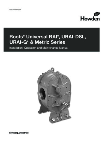
Transcription
www.howden.comwww.howden.comRoots* Universal RAI*, URAI-DSL,Roots*&UniversalRAI*, URAI-DSL,URAI-G*Metric SeriesURAI-G* & Metric SeriesInstallation, Operation and Maintenance ManualInstallation Operation & Maintenance ManualISRB 2002 GEA 19171 Roots URAI.indd 117/09/2015 12:52
ContentsInformation Summary.2Troubleshooting.11Safety Precautions.3Inspection & Maintenance.12Operating chnical Supplement for URAI-G blowers .8Assembly Drawings.18-23Lubrication.8-9Parts List.24-25Operation.10Basic Connection & Drive Shaft Information.26-28Do these things to get the most from your Roots* Blower Check shipment for damage. If found, file claim withcarrier and notify Howden Roots.Unpack shipment carefully, and check contentsagainst Packing List. Notify Howden Roots if ashortage appears.Store in a clean, dry location until ready forinstallation. Lift by methods discussed underINSTALLATION to avoid straining or distorting theequipment. Keep covers on all openings. Protectagainst weather and corrosion if outdoor storage isnecessary.Read OPERATING LIMITATIONS andINSTALLATION sections in this manual and plan thecomplete installation.Provide for adequate safeguards against accidentsto persons working on or near the equipment duringboth installation and operation. See SAFETYPRECAUTIONS.Install all equipment correctly. Foundation designmust be adequate and piping carefully done. Userecommended accessories for operating protection.Make sure both driving and driven equipment iscorrectly lubricated before start-up. SeeLUBRICATION. Read starting check points under OPERATION. Runequipment briefly to check for installation errors andmake corrections. Follow with a trial run undernormal operating conditions.In event of trouble during installation or operation, donot attempt repairs of Howden Roots furnishedequipment. Notify Howden Roots, giving allnameplate information plus an outline of operatingconditions and a description of the trouble.Unauthorized attempts at equipment repair may voidHowden Roots warranty.Units out of warranty may be repaired or adjusted bythe owner. Good inspection and maintenancepractices should reduce the need for repairs.NOTE: Information in this manual is correct as of thedate of publication. Howden Roots reserves the rightto make design or material changes without notice,and without obligation to make similar changes onequipment of prior manufacture.Roots products are sold subject to the current General Terms of Sale, ES104 and Warranty Policy WP-5020.Copies are available upon request.ISRB 2002 GEA 19171 Roots URAIISRB 2002 GEA 19171 Roots URAI.indd 2Page 2 of 3217/09/2015 12:52
Safety PrecautionsIt is important that all personnel observe safetyprecautions to minimize the chances of injury. Amongmany considerations, the following should be particularlynoted: Blower casing and associated piping or accessories maybecome hot enough to cause major skin burns oncontact.Internal and external rotating parts of the blower anddriving equipment can produce serious physical injuries.Do not reach into any opening in the blower while it isoperating, or while subject to accidental starting. Protectexternal moving parts with adequate guards.Disconnect power before doing any work, and avoidbypassing or rendering inoperative any safety orprotective devices.If blower is operated with piping disconnected, place astrong coarse screen over the inlet and avoid standing inthe discharge air stream.CAUTION: Never cover the blower inlet with yourhand or other part of body. Stay clear of the blast from pressure relief valves andthe suction area of vacuum relief valves.Use proper care and good procedures in handling,lifting, installing, operating and maintaining theequipment.Casing pressure must not exceed 25 PSI (1725 mbar)gauge. Do not pressurize vented cavities from anexternal source, nor restrict the vents without firstconsulting Roots.Do not use air blowers on explosive or hazardousgases.Other potential hazards to safety may also beassociated with operation of this equipment. Allpersonnel working in or passing through the area shouldbe trained to exercise adequate general safetyprecautions.Operating LimitationsA Roots blower or exhauster must be operated withincertain approved limiting conditions to enable continuedsatisfactory performance. Warranty is contingent onsuch operation. Maximum limits for pressure, temperature and speedare specified in Table 1 for various models & sizes ofblowers and exhausters. These limits apply to all units ofnormal construction, when operated under standardatmospheric conditions. Be sure to arrange connectionsor taps for instruments, thermometers and pressure orvacuum gauges at or near the inlet and dischargeconnections of the unit. These, along with a tachometer,will enable periodic checks of operating conditions. PRESSURE – The pressure rise, between inlet anddischarge, must not exceed the figure listed for thespecific unit frame size concerned. Also, in any systemwhere the unit inlet is at a positive pressure aboveatmosphere a maximum case rating of 25 PSI gauge(1725 mbar) should not be exceeded without firstconsulting Roots. Never should the maximum allowabledifferential pressure be exceeded.On vacuum service, with the discharge to atmosphericpressure, the inlet suction or vacuum must not begreater than values listed for the specific frame size.TEMPERATURE – Blower & exhauster frame sizes areapproved only for installations where the followingtemperature limitations can be maintained in service:ISRB 2002 GEA 19171 Roots URAIISRB 2002 GEA 19171 Roots URAI.indd 3 Measured temperature rise must not exceed listedvalues when the inlet is at ambient temperature.Ambient is considered as the general temperature of thespace around the unit. This is not outdoor temperatureunless the unit is installed outdoors.If inlet temperature is higher than ambient, the listedallowable temperature rise values must be reduced by2/3 of the difference between the actual measured inlettemperature and the ambient temperature.The average of the inlet and discharge temperaturemust not exceed 250 F. (121 C).The ambient temperature of the space the blower/motoris installed in should not be higher than 120 F (48.8 C).SPEED – These blowers & exhausters may be operatedat speeds up to the maximum listed for the variousframe sizes. They may be direct coupled to suitableconstant speed drivers if pressure/temperatureconditions are also within limits. At low speeds,excessive temperature rise may be a limiting factorSpecial Note: The listed maximum allowabletemperature rise for any particular blower & exhaustermay occur well before its maximum pressure or vacuumrating is reached. This may occur at high altitude, lowvacuum or at very low speed. The units’ operating limitis always determined by the maximum rating reachedfirst. It can be any one of the three: Pressure,Temperature or Speed.Page 3 of 3217/09/2015 12:52
InstallationRoots blowers & exhausters are treated after factoryassembly to protect against normal atmosphericcorrosion. The maximum period of internal protection isconsidered to be one year under average conditions, ifshipping plugs and seals are not removed. Protectionagainst chemical or salt water atmosphere is notprovided. Avoid opening the unit until ready to startinstallation, as corrosion protection will be quickly lostdue to evaporation.If there is to be an extended period between installationand start up, the following steps should be taken toensure corrosion protection. Coat internals of cylinder, gearbox and drive endbearing reservoir with Nox-Rust VCI-10 or equivalent.Repeat once a year or as conditions may require. NoxRust VCI-10 is petroleum soluble and does not have tobe removed before lubricating. It may be obtained fromDaubert Chemical Co., 2000 Spring Rd., Oak Brook, Ill.60521.Paint shaft extension, inlet and discharge flanges, andall other exposed surfaces with Nox-Rust X-110 orequivalent.Seal inlet, discharge, and vent openings. It is notrecommended that the unit be set in place, piped to thesystem, and allowed to remain idle for extended periods.If any part is left open to the atmosphere, the Nox-RustVCI-10 vapor will escape and lose its effectiveness.Protect units from excessive vibration during storage.Rotate shaft three or four revolutions every two weeks.Prior to start up, remove flange covers on both inlet anddischarge and inspect internals to insure absence ofrust. Check all internal clearances. Also, at this time,remove gearbox and drive end bearing cover andinspect gear teeth and bearings for rust.Because of the completely enclosed unit design,location of the installation is generally not a criticalmatter. A clean, dry and protected indoor location ispreferred. However, an outdoor location will normallygive satisfactory service. Important requirements arethat the correct grade of lubricating oil be provided forexpected operating temperatures, and that the unit belocated so that routine checking and servicing can beperformed conveniently. Proper care in locating driverand accessory equipment must also be considered.Supervision of the installation by a Howden RootsService Engineer is not usually required for these units.Workmen with experience in installing light to mediumweight machinery should be able to produce satisfactoryresults. Handling of the equipment needs to beaccomplished with care, and in compliance with safepractices. Unit mounting must be solid, without strain orISRB 2002 GEA 19171 Roots URAIISRB 2002 GEA 19171 Roots URAI.indd 4twist, and air piping must be clean, accurately alignedand properly connected.Bare-shaft Units: Two methods are used to handle aunit without base. One is to use lifting lugs bolted intothe top of the unit headplates. Test them first fortightness and fractures by tapping with a hammer. Inlifting, keep the direction of cable pull on these bolts asnearly vertical as possible. If lifting lugs are notavailable, lifting slings may be passed under the cylinderadjacent to the headplates. Either method preventsstrain on the extended drive shaft.Packaged Units: When the unit is furnished mountedon a baseplate, with or without a driver, use of liftingslings passing under the base flanges is required.Arrange these slings so that no strains are placed on theunit casing or mounting feet, or on any mountedaccessory equipment. DO NOT use the lifting lugs in thetop of the unit headplates.Before starting the installation, remove plugs, covers orseals from unit inlet and discharge connections andinspect the interior completely for foreign material. Ifcleaning is required, finish by washing the cylinder,headplates and impeller thoroughly with an appropriatesolvent. Turn the drive shaft by hand to make sure thatthe impellers turn freely at all points. Anti-rust compoundon the connection flanges and drive shaft extension mayalso be removed at this time with the same solvent.Cover the flanges until ready to connect piping.MountingCare will pay dividends when arranging the unitmounting. This is especially true when the unit is a“bare-shaft” unit furnished without a baseplate. Theconvenient procedure may be to mount such a unitdirectly on a floor or small concrete pad, but thisgenerally produces the least satisfactory results. Itdefinitely causes the most problems in levelling andalignment and may result in a “Soft Foot” condition.Correct soft foot before operation to avoid unnecessaryloading on the casing and bearings. Direct use ofbuilding structural framing members is notrecommended.For blowers without a base, it is recommended that awell anchored and carefully levelled steel or cast ironmounting plate be provided. The plate should be at least1 inch (25 mm) thick, with its top surface machined flat,and large enough to provide levelling areas at one sideand one end after the unit is mounted. It should haveproperly sized studs or tapped holes located to matchthe unit foot drilling. Proper use of a high qualitymachinist’s level is necessary for adequate installation.Page 4 of 3217/09/2015 12:52
With the mounting plate in place and levelled, set theunit on it without bolting and check for rocking. If it is notsolid, determine the total thickness of shims requiredunder one foot to stop rocking. Place half of this undereach of the diagonally-opposite short feet, and tightenthe mounting studs or screws. Rotate the drive shaft tomake sure the impellers turn freely. If the unit is to bedirect coupled to a driving motor, consider the height ofthe motor shaft and the necessity for it to be alignedvery accurately with the unit shaft. Best unitarrangement is directly bolted to the mounting platewhile the driver is on shims of at least 1/8 inch (3mm)thickness. This allows adjustment of motor position infinal shaft alignment by varying the shim thickness.AligningWhen unit and driver are factory mounted on a commonbaseplate, the assembly will have been properly alignedand is to be treated as a unit for levelling purposes.Satisfactory installation can be obtained by setting thebaseplate on a concrete slab that is rigid and free ofvibration, and levelling the top of the base carefully intwo directions so that it is free of twist. The slab must beprovided with suitable anchor bolts. The use of groutingunder and partly inside the levelled and shimmed baseis recommended.It is possible for a base-mounted assembly to becometwisted during shipment, thus disturbing the originalalignment. For this reason, make the following checksafter the base has been levelled and bolted down.Disconnect the drive and rotate the unit shaft by hand. Itshould turn freely at all points. Loosen the unit foot holddown screws and determine whether all feet are evenlyin contact with the base. If not, insert shims as requiredand again check for free impeller rotation. Finally, if unitis direct coupled to the driver, check shaft and couplingalignment carefully and make any necessarycorrections.In planning the installation, and before setting the unit,consider how piping arrangements are dictated by theunit design and assembly. Drive shaft rotation must beestablished accordingly and is indicated by an arrownear the shaft.Typical arrangement on vertical units has the drive shaftat the top with counterclockwise rotation and dischargeto the left. Horizontal units are typically arranged withthe drive shaft at the left with counterclockwise rotationand discharge down. See Figure 4 for other various unitarrangements and possible conversions.When a unit is DIRECT COUPLED to its driver, thedriver RPM must be selected or governed so as not toISRB 2002 GEA 19171 Roots URAIISRB 2002 GEA 19171 Roots URAI.indd 5exceed the maximum speed rating of the unit. Refer toTable 1 for allowable speeds of various unit sizes.A flexible type coupling should always be used toconnect the driver and unit shafts.When direct coupling a motor or engine to a blower youmust insure there is sufficient gap between the couplinghalves and the element to prevent thrust loading theblower bearings. When a motor, engine or blower isoperated the shafts may expand axially. If the couplingis installed in such a manner that there is not enoughroom for expansion the blower shaft can be forcedback into the blower and cause the impeller to contactthe gear end headplate resulting in damage to theblower. The two shafts must be in as near perfectalignment in all directions as possible, and the gap mustbe established with the motor armature on its electricalcenter if end-play exists. Coupling manufacturer’srecommendations for maximum misalignment, althoughacceptable for the coupling, are normally too large toachieve smooth operation and maximum life of theblower.The following requirements of a good installation arerecommended. When selecting a coupling to be fitted tothe blower shaft Howden Roots recommends a taperlock style coupling to insure proper contact with theblower shaft. If the coupling must have a straight borethe coupling halves must be fitted to the two shafts witha line to line thru .001” interference fit. Coupling halvesmust be warmed up per coupling manufacturer’srecommendations. Maximum deviation in offsetalignment of the shafts should not exceed .005" (.13mm) total indicator reading, taken on the two couplinghubs. Maximum deviation from parallel of the insidecoupling faces should not exceed .001" (.03 mm) whenchecked at six points around the coupling.When a unit is BELT DRIVEN, the proper selection ofsheave diameters will result in the required unit speed.When selecting a sheave to be fitted to the blower shaftHowden Roots recommends a taper lock style sheave toinsure proper contact with the blower shaft. Thisflexibility can lead to operating temperature problemscaused by unit speed being too low. Make sure the drivespeed selected is within the allowable range for thespecific unit size, as specified under Table 1.Belt drive arrangements usually employ two or more Vbelts running in grooved sheaves. Installation of thedriver is less critical than for direct coupling, but its shaftmust be level and parallel with the unit shaft. The drivershould be mounted on the inlet side of a vertical unit(horizontal piping) and on the side nearest to theshaft on a horizontal unit. SEE PAGE 6 - AcceptablePage 5 of 3217/09/2015 12:52
Blower Drive Arrangement Options. The driver mustalso be mounted on an adjustable base to permitinstalling, adjusting and removing the V-belts. Toposition the driver correctly, both sheaves need to bemounted on their shafts and the nominal shaft centerdistance known for the belt lengths to be used.CAUTION: Drive couplings and sheaves (pulleys)should have an interference fit to the shaft of the blower(set screw types of attachment generally do not providereliable service.) It is recommended that the drivecoupling or sheave used have a taperlock style bushingwhich is properly sized to provide the correctinterference fit required. Drive couplings, that requireheating to fit on the blower shaft, should be installed percoupling manufacturer recommendations. A drivecoupling or sheave should not be forced on to the shaftof the blower as this could affect internal clearancesresulting in damage to the blower.Engine drive applications often require specialconsideration to drive coupling selection to avoidharmful torsional vibrations. These vibrations maylead to blower damage if not dampened adequately.It is often necessary to install a fly-wheel and/or atorsionally soft elastic element coupling based onthe engine manufacturer recommendations.The driver sheave should also be mounted as close toits bearing as possible, and again should fit the shaftcorrectly. Position the driver on its adjustable base sothat 2/3 of the total movement is available in thedirection away from the unit, and mount the assembly sothat the face of the sheave is accurately in line withISRB 2002 GEA 19171 Roots URAIISRB 2002 GEA 19171 Roots URAI.indd 6the unit sheave. This position minimizes belt wear, andallows sufficient adjustment for both installing andtightening the belts. After belts are installed, adjust theirtension in accordance with the manufacturer’sinstructions. However, only enough tension should beapplied to prevent slippage when the unit is operatingunder load. Excessive tightening can lead to earlybearing concerns or shaft breakage.Before operating the drive under power to check initialbelt tension, first remove covers from the unitconnections. Make sure the interior is still clean, andthen rotate the shaft by hand. Place a coarse screenover the inlet connection to prevent anything beingdrawn into the unit while it is operating, and avoidstanding in line with the discharge opening. Put oil in thesumps per instructions under LUBRICATION.PipingBefore connecting piping, remove any remaining antirust compound from unit connections. Clean pipe shouldbe no smaller than unit connections. In addition, makesure it is free of scale, cuttings, weld beads, or foreignmaterial of any kind. To further guard against damage tothe unit, especially when an inlet filter is not used, installa substantial screen of 16 mesh backed with hardwarecloth at or near the inlet connections. Make provisions toclean this screen of collected debris after a few hours ofoperation. It should be removed when its usefulness hasended, as the wire will eventually deteriorate and smallpieces going into the unit may cause serious damage.Page 6 of 3217/09/2015 12:52
Pipe flanges or male threads must meet the unitconnections accurately and squarely. DO NOT attemptto correct misalignment by springing or cramping thepipe. In most cases this will distort the unit casing andcause impeller rubbing. In severe cases it can preventoperation or result in a broken drive shaft. For similarreasons, piping should be supported near the unit toeliminate dead weight strains. Also, if pipe expansion islikely to occur from temperature change, installation offlexible connectors or expansion joints is advisable.Figure 3 represents an installation with all accessoryitems that might be required under various operatingconditions. Inlet piping should be completely free ofvalves or other restrictions. When a shut-off valvecannot be avoided, make sure a full size vacuum relief isinstalled nearest the unit inlet. This will protect againstunit overload caused by accidental closing of the shutoffvalve.Need for an inlet silencer will depend on unit speed andpressure, as well as sound-level requirements in thegeneral surroundings. An inlet filter is recommended,especially in dusty or sandy locations. A dischargesilencer is also normally suggested, even thoughWHISPAIR* units operate at generally lower noise levelsthan conventional rotary blowers. Specificrecommendations on silencing can be obtained fromISRB 2002 GEA 19171 Roots URAIISRB 2002 GEA 19171 Roots URAI.indd 7your local Howden Roots distributor. Discharge pipingrequires a pressure relief valve, and should include amanual unloading valve to permit starting the unit underno-load conditions. Reliable pressure/vacuum gaugesand good thermometers at both inlet and discharge arerecommended to allow making the important checks onunit operating conditions. The back-pressure regulatorshown in Figure 3 is useful mainly when volumedemands vary while the unit operates at constant output.If demand is constant, but somewhat lower than the unitoutput, excess may be blown off through the manualunloading valve.In multiple unit installations where two or more unitsoperate with a common header, use of check valves ismandatory. These should be of a direct acting or freeswinging type, with one valve located in each linebetween the unit and header. Properly installed, they willprotect against damage from reverse rotation caused byair and material back-flow through an idle unit.After piping is completed, and before applying power,rotate the drive shaft by hand again. If it does not movewith uniform freedom, look for uneven mounting, pipingstrain, excessive belt tension or coupling misalignment.DO NOT operate the unit at this time unless it has beenlubricated per instructions.Page 7 of 3217/09/2015 12:52
grease, preventing pressure build-up on the seals. Arestriction plug and metering orifice prevent loss oflubricant from initial surges in lubricant pressure butpermit venting excess lubricant under steadily risingpressures.Technical Supplement for URAI-G Gas BlowersTechnical Supplement for 32, 33, 36, 42, 45, 47, 53,56, 59, 65, 68, 615 Universal RAI-G blowersPrecaution: URAI-G blowers: Care must be used whenopening the head plate seal vent chamber plugs (43) assome gas will escape–if it is a pressure system, or theatmospheric air will leak into the blower if the system isunder vacuum. There is a possibility of some gasleakage through the mechanical seals. This leakage onthe gear end will escape through the gear box vent, andon the drive end, through the grease release fittings. Ifthe gas leakage is undesirable, each seal chamber mustbe purged with an inert gas through one purge gas hole(43) per seal. There are two plugged purge gas holes(1/8 NPT) provided per seal. The purge gas pressuremust be maintained one PSI above the discharge gaspressure. Also, there exists a possibility of gear end oiland drive end grease leakage into the gas stream.Using a pressure gun, slowly force new lubricant intoeach drive end bearing housing until traces of cleangrease comes out of the relief fitting. The use of anelectric or pneumatic grease gun could force the greasein too rapidly and thus invert the seals and should not beused.Gear end bearings, gears and oil seals are lubricated bythe action of the timing gears which dip into the main oilsumps causing oil to splash directly on gears and intobearings and seals. A drain port is provided below eachbearing to prevent an excessive amount of oil in thebearings. Seals located inboard of the bearings in eachheadplate effectively retain oil within the sumps. Anysmall weepage that may occur should the seals wearpasses into a cavity in each vented headplate and isdrained downward.Roots Universal RAI-G rotary positive gas blowers are adesign extension of the basic Roots Universal RAIblower model. URAIG blower uses (4) mechanical sealsin place of the standard inboard lip seals to minimizegas leakage into the atmosphere.Proper lubrication is usually the most important singleconsideration in obtaining maximum service life andsatisfactory operation from the unit. Unless operatingconditions are severe, a weekly check of oil level andnecessary addition of lubricant should be sufficient.These units are intended for gases which are compatiblewith cast iron case material, steel shafts, 300/400 seriesstainless steel and carbon seal components, viton orings and the oil/ grease lubricants. If there are anyquestions regarding application or operation of this gasblower, please contact factory.A simple but very effective lubrication system isemployed on the drive shaft end bearings. Hydraulicpressure relief fittings are provided to vent any excessMore frequent oil service may be necessary if the bloweris operated in a very dusty location.Lubricationbreather and the overflow plug back into their respectiveholes.The lubrication should be changed after initial 100 hoursof operation.Proper service intervals of the oil thereafter are basedon the discharge air temperature of the blower. Pleaserefer to the information below to “How to properlydetermine the oil service intervals” shown on this page.Unless operating conditions are quite severe, a weeklycheck of the oil level and necessary addition of lubricantshould be sufficient. During the first week of operation,check the oil levels in the oil sumps about once a day,and watch for leaks. Replenish as necessary.If you choose to use another oil other than the specifiedand recommended ROOTS Synthetic, use a good gradeof industrial type non-detergent, rust inhibiting, antifoaming oil and of correct viscosity per Table 2, page 16.Due to sludge build-up and seal leakage problems,Howden Roots recommendation is DO NOT USEMobil SHC synthetic oils in Roots blowers.Proper lubrication is usually the most importantsingle consideration in obtaining maximum servicelife and satisfactory operation from the unit.URAI Air and Gas gear end bearing lubrication/oilwith splash lubrication on the gear end only (Driveend grease lubricated). During the first week of operation, check the oil levels inthe oil sumps about once a day, and watch for leaks.Replenish as necessary. Thereafter, an occasionalcheck should be sufficient.The specified and recommended oil is Roots SyntheticOil of correct viscosity per Table 2, page 16.To fill the gearbox, remove the breather plug (25) andthe oil overflow plug (21) - see page 15. Fill the reservoirup to the overflow hole. DO NOT OVERFILL. Place theISRB 2002 GEA 19171 Roots URAIISRB 2002 GEA 19171 Roots URAI.indd 8 Page 8 of 3217/09/2015 12:52
NOTE: To estimate oil temperature, multiply thedischarge temperature of the blower by 0.80. Example: ifthe discharge air temperature of the blower is 200 F, itis estimated that the oil temperature is 160 FHowden Roots does NOT recommend the use ofautomotive type lubricants, as they are not formulatedwith the properties mentioned above.Roots URAI-DSL blowers with splash lubrication/oilon each end. No grease.The specified and recommended oil is Roots SyntheticOil of correct viscosity per Table 2, page 16.The lubrication should be changed after initial 100 hoursof operation.The proper oil level should be half way or middle of thesight gauge when the blower is not operating. DO NOTOVERFILL OIL SUMP/S as damage to the blower mayoccur.The oil level should not fall below the middle of the sitegauge when the blower is idle.The lubrication/oil level may rise or fall in the gaugeduring operation to an extent depending somewhat onoil temperature and blower speed. Proper serviceintervals of the oil thereafter are based on the dischargeair temperature of the blower. Please refer to theinformation below to “How to properly determine the oilservice intervals” shown on this page.Unless operating conditions are quite severe, a weeklycheck of the oil level and necessary addition of lubrican
Roots* Universal RAI*, URAI-DSL, URAI-G* & Metric Series Installation Operation & Maintenance Manual www.howden.com Installation, Operation and Maintenance Manual Roots* Universal RAI*, URAI-DSL, URAI-G* & Metric Series ISRB_2002 GEA 19171 Roots URAI.indd 1 17/09/2015 12:52
