Transcription
—AP P L I CATI O N N OT EIRC5 ROBOT CONTROLLER AND CI502WITH SAFETY I/O MODULESSETTING UP THE IRC5 WITH “PREPARED FORABB CI502”
Contents1 Introduction . 31.1Scope .31.2Terms and abbreviations .31.3References . 42 Setup overview .53 Installation and configuration . 63.1Prerequisites . 63.1.1Hardware . 63.1.2Software and firmware versions . 73.2Hardware setup . 73.3PROFINET setup . 83.3.1PROFINET configuration . 83.3.2CI502 PROFINET configuration . 123.4CI502 module configuration .143.4.1CI502 standard I/O channels . 153.5DX581-S configuration .183.5.2DX581-S signals .233.6DI581-S configuration . 283.6.2DI581-S signals. 333.7Reintegration of safety I/O channels . 383.8SafeMove2 configuration . 393.9Downloading the configuration to IRC5 .414 Summary . 422Document No. 3ADR010316, Rev. A
1Introduction1.1ScopeThis application note describes how to configure S500 safety I/O modules that areconnected to an IRC5 controller with the “Prepared for ABB CI502” option (Product ID:3HAC064043-001). It gives a detailed description of the I/O channel configuration of DX581-Sand DI581-S safety I/O modules using ABB RobotStudio.This documentation is intended for qualified personnel familiar with functional safety. Youmust read and understand the safety concepts and requirements presented in the referenceddocumentation before you operate an IRC5 system with safety I/O modules.This application note is relevant for: Personnel responsible for the installation and configuration of the fieldbus hardwareand software of IRC5 systems. Personnel that configure IRC5 I/O systems. System integrators who use IRC5 robot controllers.1.2 Terms and abbreviationsThe table below explains the abbreviations used in the document.AbbreviationDescriptionCI502ABB CI502-PNIO PROFINET IO Bus Module / Communication interfacemodule, Product ID: 1SAP220700R0001.A PROFINET IO device module used to connect to a PROFINET IO controller.Up to 10 S500 I/O modules (standard and/or safety) can be attached to it.CRCCyclic redundancy check. A number derived from and stored or transmittedwith a block of data to detect data corruption.DCConfigurable digital input or output. It can be used as an input and/or anoutput.I/OInput/OutputIPInternet protocolOSSDOutput Signal Switching DevicePassivationA special state of safety I/O modules which leads to the delivery of safesubstitute values, which are “0” values for S500 safety I/O modules.PLCProgrammable logic controllerPROFINETAn industrial technical standard for data communication over IndustrialEthernet.Reintegration The process of switching from substitute values “0” to the process data.RWRobotWare (Firmware of IRC5 controller)S500ABB I/O modules which can be used with the ABB IRC5 robot controllerTUTerminal UnitDocument No. 3ADR010316, Rev. A3
1.3 ReferencesThe table below shows the related documents with the download links.RefType, Title, Document-ID, Download-Link, Version[1]AC500-S Unbundled S500 Safety I/Os, load.aspx?DocumentID 3ADR024128K0201&LanguageCode en&DocumentPartId &Action Launchor newer version 3ADR024128K02** (** sequential version number)[2]AC500-S Safety User Manual, load.aspx?DocumentID 3ADR025091M0207&Language-Code en&DocumentPartId &Action Launchor newer version 3ADR025091M02** (** sequential version number)[3]CI502-PNIO (-XC) Description, load.aspx?DocumentID 3ADR024127K0201&Language-Code en&DocumentPartId &Action Launch,or newer version 3ADR024127K02** (** sequential version number)[4]Functional Safety and SafeMove2, ad.aspx?DocumentID 3HAC052610001&LanguageCode en&DocumentPartId &Action LaunchG (RW6.07) or newer[5]Usage of unbundled S500 safety I/Os and AC500-S F iPar CRC brary/Download.aspx?DocumentID 3ADR020122K0201&LanguageCode en&DocumentPartId &Action Launch[6]Operating manual of RobotStudio, ad.aspx?DocumentID 3HAC032104001&LanguageCode en&DocumentPartId &Action LaunchRevision D or newer[7]PROFINET Controller/Device I/O library/Download.aspx?DocumentID 3HAC065546001&LanguageCode en&DocumentPartId &Action Launchto be found in RobotStudio Help in “Additional Resources” section.Revision B or newer[8]4User Documentation DVD for all IRBs, 875-001/userdoc-dvd-for-all-irbsDocument No. 3ADR010316, Rev. A
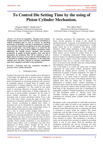
2Setup overviewThis manual focuses on the configuration of ABB S500 safety I/O modules connected to anIRC5 controller via PROFINET, using the IRC5 “Prepared for ABB CI502” option, as shown inFig. 1.Fig. 1: IRC5 controller with SafeMove2 and ABB safety I/Os configured using the “Prepared forABB CI502” optionThe solution with the “Prepared for ABB CI502” robot controller option described in thisapplication note offers: Connection of safety sensors such as light curtains, laser scanners, safety mats, etc.directly to the SafeMove2 safety controller, for example, for installations withoutsafety fieldbus equipped PLCs. Prepared in terms of software support (that is, no hardware, wiring, and so on) inABB RobotStudio. Replacement of SafeMove1 functionality. “Prepared for ABB CI502” offers the same functionality as F-Host, but is limited toABB safety I/O modules from ABB Automation Products. A CI502 PROFINET IO communication interface module with on-board standard I/Osis used to attach ABB safety I/O modules.Key characteristics of the solution with the “Prepared for ABB CI502” robot controller option: No explicit need for the PROFIsafe F-Host robot controller option. Higher flexibility and productivity with SafeMove2 features and the “Prepared for ABBCI502” option. Smaller safety distances due to faster safety response times.Document No. 3ADR010316, Rev. A5
3Installation and configurationThis chapter describes the prerequisites, hardware and PROFINET setup to connect ABBDI581-S and DX581-S safety I/O modules and the CI502 communication interface module. Theconfiguration and special parameters of the DX581-S and DI581-S safety I/O modules aredescribed in detail. This includes the description of how to use the diagnostic signals of theDX581-S and DI581-S safety I/O modules to reintegrate passivated safety channels, forexample, in the case of detected cross-talk wiring errors, and so on.3.1 PrerequisitesTo complete the tasks described in this application note, the reader must have expertise of: Mechanical and electrical installation work with the IRC5 robot controller. The system and fieldbus parameter configuration of the IRC5 robot controller. The configuration of the SafeMove2 option in the IRC5 robot controller.For more information, refer to [4], [6] and [7].3.1.1HardwareThe following hardware is needed:6Hardware nameCommentsIRC5 robot controller with options:Refer to the ABB Robotics catalog from2018 (or newer) 1241-1 “Prepared for ABB CI502” 888-2 “PROFINET Controller Device” 996-1 “Safety Module“CI502-PNIOCI502-PNIO (V3): S500, PROFINET IOcommunication interface module with 8 DI,8 DO and 8 DC channels, Order code:1SAP220700R0001TU508-ETHTU508-ETH: S500, ETH terminal unit, springterminals, Order code: 1SAP214000R0001DI581-SDI581-S: S500, Safety digital input module16SDI, Order code: 1SAP284000R0001DX581-SDX581-S: S500, Safety digital I/O module8SDI/SDO, Order code: 1SAP284100R0001TU582-STU582-S: S500, Safety I/O terminal unit,spring terminals, 24V DC, Order code:1SAP281200R0001Document No. 3ADR010316, Rev. A
3.1.2Software and firmware versionsThe functionality described in this application note was tested with the following componentsoftware Additional options are required:IRC5 RobotControllerRW tStudio6.08 1241-1 “Prepared for ABB CI502” 888-2 “PROFINET Controller/Device” 996-1 “Safety Module”These can be ordered from ABB Robotics.PROFINET IO communication interface moduleIt can be ordered from ABB Automation Products.Safety digital input/output moduleIt can be ordered from ABB Automation Products.Safety digital input moduleIt can be ordered from ABB Automation Products.Download tstudio/downloadsThis software tool is needed to calculate CRC forindividual safety I/O module parameters.AC500-SF iPar CRCCalculator3.2Download .aspx?DocumentID 9AKK106713A4484&LanguageCode en&DocumentPartId &Action LaunchHardware setupThis section gives references to the hardware setup of IRC5 robot controller with S500 safetyI/O modules using the “Prepared for ABB CI502” option.The hardware setup of the IRC5 robot controller and related components is described in [8].The installation instructions for S500 safety I/O modules are listed in the “References”section in [1]. A note on connections: Connect 24V DC to terminals 1.8 (UP) and 3.8 (UP3) on TU508-ETH. Connect 0V to terminal 1.9 (ZP) on TU508-ETH. Connect 24V DC and 0V separately to the attached DI581-S and/or DX581-S safetyI/O modules, respectively, to 1.8 (UP) and 1.9 (ZP) on TU582-S.Examples of possible sensor and actor connections to the DI581-S and DX581-S safety I/Omodules are listed in the “Circuit examples” sections in [2].Document No. 3ADR010316, Rev. A7
3.3PROFINET setupThe S500 safety I/O modules are attached to the CI502 PROFINET IO communicationinterface module, which is used as a communication interface for connectivity to the IRC5robot controller. This section describes how to setup the PROFINET parameters of the CI502module.3.3.1PROFINET configuration1.Open RobotStudio and connect to the IRC5 controller.2.Open the I/O Configurator: Select “Controller” “Configuration” “I/O Configurator”.Note that you may have to change the window settings to see the “Properties” view. Todo so, right-click on “I/O Configurator” “Windows” and then select “Properties”.8Document No. 3ADR010316, Rev. A
3.Configure the PROFINET properties.Open the PROFINET controller properties in the “Configuration” tab using“Communication” “IP Setting” “PROFINET Network”.Enter the “IP-Address”, “Subnet” and the LAN “Interface” in the “Properties” tab (refer tothe example below).After this step, the warning sign on the “PROFINET Network” node in the treedisappears.4.Enter a PROFINET Station Name.Open the PROFINET properties in the “Configuration” tab using “I/O System” “PROFINET”.Document No. 3ADR010316, Rev. A9
In the “Configuration” tab, enter a valid PROFINET name, for example, “irc5-pnio”.PROFINET names can only consist of small letters and/or numbers and/or “-”.After this step, the warning sign on the “PROFINET” node in the tree below “I/O System”disappears.5.Add the CI502 PROFINET IO communication interface module and the DX581-S and/orDI581-S safety I/O modules in the RobotStudio project.In the “Configuration” tab, select “I/O System” “PROFINET” “Controller”, open“Device Catalogue” and select the “CI502-PNIO (V3)” device.Double-click on “CI502-PNIO (V3)” to add the CI502 module to the robot PROFINETController.10Document No. 3ADR010316, Rev. A
Select the “CI502 PNIO V3” node in the “Configuration” tab and the “Device Catalogue”tab will show all S500 devices which can be attached to the CI502 module. Add “DX581-SInput/Output (Safety)” and/or “DI581-S Input (Safety)” devices from the devicecatalogue by double-clicking the devices.The selected devices appear as nodes under the “CI502 PNIO V3” node.Document No. 3ADR010316, Rev. A11
3.3.2CI502 PROFINET configurationTo configure the CI502 PROFINET parameters, select the “CI502-PNIO V3” device in the“Configuration” tab and activate the “Properties” tab as shown below.Configure the parameters in the “Properties” tab as required.12Document No. 3ADR010316, Rev. A
The key parameters are explained in the table below. For more information on CI502parameters, refer to [3].ParameterDescriptionPROFINET Station nameThis parameter defines the PROFINET name for the PROFINET IOdevice. There are two options to set the PROFINET IO device namefor CI502 modules:Option 1, “Allocation of the Device Name via DCP”:The allocation of the device name via DCP is standard forPROFINET networks. For this method of allocation, you must setboth rotary address switches to "0" on the CI502 module.Option 2, “Allocation of the Device Name via Address Switches”:The CI502 has 2 rotary switches to set an explicit name to thePROFINET IO device before commissioning. No engineering tool isneeded. The device gets its name (including the fixed part of thedevice name) directly from the switch settings (01h.FFh). Thisname can be used directly within the device configuration:“ci502-pn-xx”Note: "ci502-pn-” is the fixed part of the device name and xxrepresents the position of the rotary switch (0.FFh or 0.255d).The rotary switches have hexadecimal values. For example, to setthe name to “ci502-pn-08”, set the upper rotary switch to “0” andthe lower switch to “8”.For the detailed descriptions of the options and how to set the“PROFINET Station name” for CI502, refer to “Allocation of theDevice Name” in [3].Network parameters(“IP Address”, “Subnet”and “Gateway”)Set the “IP Address” as required. It must be in the range of thePROFINET, which is configured under “Communications” “IPSettings” “PROFINET Network”, for example:IP 2.168.15.1Document No. 3ADR010316, Rev. A13
ParameterDescriptionNameDefault value: CI502 PNIO V3The name can be set as required, for example, to reflect thefunction of the I/O cluster.Identification Label3.4It can be set as required to identify the module.CI502 module configurationYou can configure the behavior of the inputs and outputs in the “Properties” tab of the CI502module and its sub-element, respectively.For the detailed descriptions of all CI502 parameters, refer to “Parameterization” of CI502 in[3].To complete the configuration tasks described in this application note, you do not need tochange the default values. The default configuration of CI502 module parameters is shownbelow.14Document No. 3ADR010316, Rev. A
3.4.1CI502 standard I/O channelsIn addition to PROFINET IO device functionality, the CI502 has 8 reserved configurable digitalinput/outputs, 8 digital inputs and 8 digital outputs, which can be used, for example, forerror acknowledgement on the IRC5 robot controller and/or CI502 with its I/O modules.For example, to add standard signals in the IRC5 robot controller and map them to the CI502I/O channels, select “CI502 InputOutput” in the “Configuration” tab and change the “Type ofSignal” to Digital Input in “Signal Editor” tab:Enter a signal name in the “Name” field and configure the “Device Mapping” according to thetables in Sections 3.4.1.1 and 3.4.1.2. Press “Enter” to insert a new line for the next signal.Document No. 3ADR010316, Rev. A15
3.4.1.1CI502 input channelsThe following table shows the offset values for signal mapping CI502 input channels in theRobotStudio “Signal riptionDigital inputs DC0-DC70-7Group input (Byte) – Digital inputs DC0-DC7Digital input DC00Digital input DC11Digital input DC22Digital input DC33Digital input DC44Digital input DC55Digital input DC66Digital input DC77Digital inputs DI8-DI15168-15Digital input DI88Digital input DI99Digital input DI1010Digital input DI1111Digital input DI1212Digital input DI1313Digital input DI1414Digital input DI1515Group input (Byte) – Digital inputs DI8-DI15Fast counter : Actual value 132-63Group input (DWord) – reserved for fast counterFast counter : Actual value 264-95Group input (DWord) – reserved for fast counterFast counter : State Byte 196-103Group input (DWord) – reserved for fast counterFast counter : State Byte 2104-111Group input (DWord) – reserved for fast counterDocument No. 3ADR010316, Rev. A
3.4.1.2CI502 output channelsThe offset values for signal mapping the CI502 output channels in the RobotStudio mark/DescriptionDigital outputs DC0-DC70-7Group output (Byte) – Digital outputs DC0-DC7Digital output DC00Digital output DC11Digital output DC22Digital output DC33Digital output DC44Digital output DC55Digital output DC66Digital output DC77Digital outputs DO8-DO158-15Digital output DO88Digital output DO99Digital output DO1010Digital output DO1111Digital output DO1212Digital output DO1313Digital output DO1414Digital output DO1515Fast counter : Start value 132-63Group output (Byte) – Digital outputs DO8-DO15Group output (DWord) – reserved for fastcounterFast counter : End value 164-95Group output (DWord) – reserved for fastcounterFast counter : Start value 296-127Group output (DWord) – reserved for fastcounterFast counter : End value 2128-159Group output (DWord) – reserved for fastcounterFast counter : Control Byte 1160-167Group output (Byte) – reserved for fast counterFast counter : Control Byte 2168-175Group output (Byte) – reserved for fast counterDocument No. 3ADR010316, Rev. A17
3.5DX581-S configurationThe DX581-S safety I/O module has 8 safety digital inputs, which can be configured as1-channel or 2-channel safety digital inputs, 8 safety digital outputs and 4 test pulse outputs.For a detailed description of all DX581-S parameters, refer to the “Parameterization” sectionof DX581-S in [2].You can configure the behavior of the inputs and outputs of the DX581-S safety I/O module inthe “Properties” tab:1.Configure the generic properties of the module.Select the “DX581 S InputOutput Safety” node and activate its “Properties” tab.ParameterDescriptionNameThe “Name” can be set as required, for example, to reflect thefunction of the DX581-S safety I/O module.Default value: “DX581 S InputOutput Safety”Identification Label18It can be set as required to identify the module.Document No. 3ADR010316, Rev. A
ParameterDescriptionDestination addressThe destination address is the so-called F Dest Add, which isused for PROFIsafe F-Device identification.Set the F Dest Add destination address according to the valueset with the two rotary hardware switches on the DX581-S safetyI/O module.Note that the F Dest Add destination address in theconfiguration must be set as a decimal value, but the rotaryswitches are set as hexadecimal values. The default setting of theDX581-S rotary switches is 02h (hexadecimal).For more information on F Dest Add, refer to [2].For information on the other parameters listed in the “Properties” tab, refer to [2].2.Configure the safety I/O channels.Select the “DX581-S Input/Output (Safety)” node and its “Properties” tab:Document No. 3ADR010316, Rev. A19
The key parameters are explained in the table below. For a detailed description of allparameters, refer to “Parameterization” in [2].ParameterDescriptionCheck supply“On”, “Off”Default value: “On”The parameter setting defines whether diagnosis messages aregenerated for this device in case of a missing power supply on“UP” terminals.Input, Channelconfiguration“Not used”, “1 channel”, “2 channel equivalent”, “2 channelantivalent”Default value: “Not used”Note that if channels are used as “2 channel equivalent” or “2channel antivalent” inputs, the following possible channelcombinations are supported: Channels 0 and 4 Channels 1 and 5 Channels 2 and 6 Channels 3 and 7Note that in “2 channel equivalent” or “2 channel antivalent”configurations you must configure the higher channel in the sameway as the lower one. In addition, only the lower channel reflectsthe result of both channels and must be used in the controllerprogram. The higher channel always delivers fail-safe “0” values inthe controller program.Input, Test pulse“Disabled”, “Enabled”Default value: “Disabled”If “Enabled” is selected, the safety input channel must be poweredby the dedicated test pulse output of the DX581-S safety I/Omodule:20 Input channels 0 and 1 shall use test pulse output T0 Input channels 2 and 3 shall use test pulse output T1 Input channels 4 and 5 shall use test pulse output T2 Input channels 6 and 7 shall use test pulse output T3Document No. 3ADR010316, Rev. A
ParameterDescriptionInput Delay“1 ms”, “2 ms”, “5 ms”, “10 ms”, “15 ms”, “30 ms”, “50 ms”, “100ms”, “200 ms”, “500 ms”Default value: 5 msSignals with a duration shorter than the input delay value are notcaptured by the safety module.For more information, refer to the “Functionality” section ofDX581-S safety I/O module in [2].2 channel configuration,Discrepancy time“10 ms”, “20 ms”, “30 ms”, “40 ms”, “50 ms”, “60 ms”, “70 ms”, “80ms”, “90 ms”, “100 ms”, “150 ms”, “200 ms”, “250 ms”, “300 ms”,“400 ms”, “500 ms”, “750 ms”, “1 s”, “2 s”, “3 s”, “4 s”, “5 s”, “10 s”,“20 s”, “30 s”Default value: 50 msIt is used in a 2-channel configuration to detect if both inputchannels have changed to the same state after the discrepancytime.Note that for OSSD devices such as laser scanners, lightcurtains, etc. it is highly recommended to set the discrepancytime to 10 ms to avoid the reintegration procedure usingdedicated acknowledge reintegration signals.In case of mechanical position switches, mode selectors, E-Stopbuttons, etc. discrepancy time values of 100 ms and above mustbe used depending on their properties.For more information, refer to “Functionality” section of theDX581-S safety I/O module in [2].Output channel“Not used”, “Used”Default value: “Not used”Output, Detection“Off”, “On”Default value: “On”The “Detection” parameter defines whether the internal outputchannel test is active.Note that the reachable SILCL (IEC 62061), SIL (IEC 61508) and PL(ISO 13849-1) levels for the safety outputs of the DX581-S safetyI/O module are only valid if the parameter Detection “On”. If theparameter detection “Off” then contact ABB technical supportto obtain proper reachable SILCL, SIL and PL levels.Document No. 3ADR010316, Rev. A21
3.Calculate I Par CRC (F iPar CRC) for the DX581-S parameters.The I Par CRC (F iPar CRC according to PROFIsafe definition) parameter is a specialparameter which defines a checksum and is used for the safe transfer of DX581-S safety I/Oparameters to physical DX581-S safety I/O modules.The checksum I Par CRC must be calculated and entered after the parameter configurationof the DX581-S safety I/O module (for example, “Destination address” parameter) and its I/Ochannels (for example, “Input delay” parameter) is complete. If DX581-S parameters arechanged later, the I Par CRC calculation must be done again.Note that to configure I Par CRC, you have to install the vendor tool “AC500-S F iPar CRCCalculator” beforehand using this ocumentID 9AKK106713A4484&LanguageCode en&DocumentPartId &Action LaunchSelect the “DX581 S InputOutput Safety” node and its “Properties” tab:Call the “Vendor Tool” by clicking on the button right to the “I Par CRC” value.22Document No. 3ADR010316, Rev. A
The “AC500-S F iPar CRC Calculator” is launched. Verify all entries, which are DX581-Sparameters, in the “AC500-S F iPar CRC Calculator” tool and acknowledge them using thecheckbox.Copy the hexadecimal value of the I Par CRC (F iPar CRC) from “AC500-S F iPar CRCCalculator” to the clipboard and paste it to the I Par CRC parameter field of the DX581-Ssafety I/O module in RobotStudio.3.5.2DX581-S signalsTo add signals to the IRC5 robot controller using the I/O configurator in RobotStudio, youmust enter the offset values for signal mapping of the DX581-S safety I/O channels. Thetables in sections 3.5.2.1 and 3.5.2.2 show the offset values for the signal mappings of theDX581-S safety I/O channels.Document No. 3ADR010316, Rev. A23
3.5.2.1DX581-S input signal mappingThe offset values for input signal mapping of the DX581-S safety I/O tionSafety digital inputs I0-I70-7Group input (Byte) – Safety digital inputs I0-I70Safety DI0. If used as a 2-channel configuration:Safety digital input I0value of the 2-channel evaluation (I0 and I4)Safety digital input I11Safety DI1. If used as a 2-channel configuration:value of the 2-channel evaluation (I1 and I5)Safety digital input I22Safety DI2. If used as a 2-channel configuration:value of the 2-channel evaluation (I2 and I6)Safety digital input I33Safety DI3. If used as a 2-channel configuration:value of the 2-channel evaluation (I3 and I7)Safety digital input I44Safety DI4. If used as a 2-channel configuration:value is always FALSE. See Safety DI0.Safety digital input I55Safety DI5. If used as a 2-channel configuration:value is always FALSE. See Safety DI1.Safety digital input I66Safety DI6. If used as a 2-channel configuration:value is always FALSE. See Safety DI2.Safety digital input I77Safety DI7. If used as a 2-channel configuration:value is always FALSE. See Safety DI3.Safe diagnostic I0-I78-15Group input (Byte) – Safety input signals toindicate the use of fail-safe values on safety DIchannelsSafe Diag – Input I08Indication of fail-safe value used on Safety DI0Safe Diag – Input I19Indication of fail-safe value used on Safety DI1Safe Diag – Input I210Indication of fail-safe value used on Safety DI2Safe Diag – Input I311Indication of fail-safe value used on Safety DI3Safe Diag – Input I412Indication of fail-safe value used on Safety DI4Safe Diag – Input I513Indication of fail-safe value used on Safety DI5Safe Diag – Input I614Indication of fail-safe value used on Safety DI6Safe Diag – Input I715Indication of fail-safe value used on Safety DI716-23Group input (Byte) – Safety input signals toSafe diagnostic O0-O7indicate the use of fail-safe values on Safety DOchannels24Safe Diag – Output O016Indication of fail-safe value used on Safety DO0Safe Diag – Output O117Indication of fail-safe value used on Safety DO1Safe Diag – Output O218Indication of fail-safe value used on Safety DO2Safe Diag – Output O319Indication of fail-safe value used on Safety DO3Safe Diag – Output O420Indication of fail-safe value used on Safety DO4Document No. 3ADR010316, Rev. A
e Diag – Output O521Indication of fail-safe value used on Safety DO5Safe Diag – Output O622Indication of fail-safe value used on Safety DO6Safe Diag – Output O723Indication of fail-safe value used on Safety DO724-31Group input (Byte) – Indication that safety inputReintegration request I0-I7channels can be reintegrated to deliver safetyprocess values instead of fail-safe “0” valuesRei Req – Input I024Safety DI0 channel can be reintegratedRei Req – Input I125Safety DI1 channel can be reintegratedRei Req – Input I226Safety DI2 channel can be reintegratedRei Req – Input I327Safety DI3 channel can be reintegratedRei Req – Input I428Safety DI4 channel can be reintegratedRei Req – Input I529Safety DI5 channel can be reintegratedRei Req – Input I630Safety DI6channel can be reintegratedRei Req – Input I731Safety DI7 channel can be reintegrated32-39Group input (Byte) – Indication that safetyReintegration request O0-O7output channels can be reintegrated to deliversafety process values instead of fail-safe “0”valuesRei Req – Output O032Safety DO0 channel can be reintegratedRei Req – Output O133Safety DO1 channel can be reintegratedRei Req – Output O234Safety DO2 channel can be reintegratedRei Req – Output O335Safety DO3 channel can be reintegratedRei Req – Output
1. Open RobotStudio and connect to the IRC5 controller. 2. Open the I/O Configurator: Select "Controller" "Configuration" "I/O Configurator". Note that you may have to change the window settings to see the "Properties" view. To do so, right-click on "I/O Configurator" "Windows" and then select "Properties".