Transcription
Special Issue - 2016International Journal of Engineering Research & Technology (IJERT)ISSN: 2278-0181NCIMACEMT - 2016 Conference ProceedingsTo Control Die Setting Time by the using ofPiston Cylinder Mechanism.Pragnesh Mehta(a), Hardik Zaler(b)Prof. Dhruv Patel(c)Department of Mechanical EngineeringB.H.Gardi College of Engineering & Technology.-Rajkot,IndiaDepartment of Mechanical EngineeringB.H.Gardi College of Engineering & Technology.-Rajkot,IndiaAbstract—To survive in competition through recent scenario,forging industry needs creativities, innovation & automations toreduced production time as well as accuracy in operatingperformance & flexibility. Lead time in manufacturer’s point ofview is the time elapse between placing of an order and actuallyreceipt of good order. Aim of this paper is to control the diesetting time by the using of piston cylinder mechanisms whichinfluencing the forging process smoothly and increasesproductivity & quality of forged products. Thus with aid ofautomation, the production time will be reduced as well ashigher degree of accuracy can be achieved which facilitates easeof operation for making forged components. As die setting timecommute gives the faster response to customer requirementsmake more competitive and aider to mass production. .So important parameters like temperature, time, Angle,Stress, Dovail, packing’s & facing of dies should bemaintained properly. At present, to do modification in designof complex die is very difficult so for optimization of designproper factor has to be considered with taking certaintolerances. While doing machining of forged componentsmajor defects occurs likewise sharp edge, burr, chillies etc.These defects can be reduced by proper Pareto & VivaAnalysis of machining components. When products areplaced in furnace for obtaining required hardness during heattreatment process defects occurs like insufficient hardness,fracturing & cracks. So as a remedy of this defects, properheat is to be given in the salt bath, select the cooling mediumand tempering is done after hardening.Aim of this paper is to control die setting time of forgedcomponents by using piston cylinder mechanism whichinfluencing the forging process smoothly by increasingproductivity & quality of forged components. For shake ofcreativeness & innovations in the forging industriesautomation is very much useful to increased efficiency.Major problems faced in many of the forging industries theyrequired more time for setting dies in hammer. Foroptimization of problem piston- cylinder mechanism isbeneficial which control die setting time on hammer. It helpsto improve the process which is more feasible to forge a part.With help of this mechanism good rate of deformation &temperature condition of forged components can be achieved[1]. This mechanism consist of Electric motor, GearAssembly, Auxiliary support of crankshaft, crank shaft,connecting rod, Auxiliary guide, Cylinder, piston, Hammer,Base plates, Legs.Keywords— Production leads time, Automation, Flexibility &Accuracy, Piston- cylinder mechanism.I.INTRODUCTIONForging is the process by which a metallic part is deformed toa final shape with application of pressure which is obtainedfrom hammer or press. In modern eras, forging industriesneeds developments by increasing production rate, precision& expanding capacity to forged larger & complex parts.Advancement in forging industries can be done by usingautomation in equipment’s [1]. This would be very muchuseful in increasing efficiency of forging industry. In thispaper to control die setting times of forged components bythe using of piston-cylinder mechanism. By the using ofpiston cylinder mechanism two types of motions aregenerating such as Linear and Rotary motion. Force is theone of the factor which, varying the angle of crank. Thismechanism is frequently utilized for getting larger amount offorce, velocity, accelerating & shaking force which, isgenerated and can be determined by analytically also. Thecrank rotary motion converts into reciprocating motion ofpiston through connecting rod inside cylinder [2].Now a day, in current scenario forging industries facingproblems are more care & reduction of die setting time isrequired for increasing productivity of forged components.This difficulty has been resolved with the help of pistoncylinder mechanism which is very beneficial to make processsmoothly. Piston cylinder mechanism is very beneficial toreduced major defects such as mismatch, Lap fold, PoorAppearance & Worm surface. Forging die life will beincreased by implementation of this mechanism. Forimproving quality of forged components various importantparameters has to be considered while doing forging process.Volume 4, Issue 10Mechanism works on the principle of crank shaft mechanismin which crank rotates by motor at any particular speed soshaft which is connected also the rotates. The spur gearsmounted on the shaft transmit power to connecting rod whichis connected to piston inside the cylinder. The pistonreciprocates with the help of rod at number of strokes as aresult of hammer which is connected to the piston strikes thedies as per required force to set die. Therefore die is set withfewer amounts of strokes. This mechanism is movable soeasily can be transfer from one place to another by providingwheels at end of base plates. With the beneficial thismechanism, production rate will be increased, less timerequired to set the die, better quality of products can beachieved with having higher accuracy & Manpower reduces.Published by, www.ijert.org1
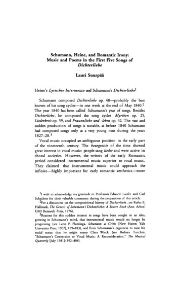
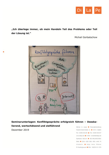
Special Issue - 2016II.International Journal of Engineering Research & Technology (IJERT)ISSN: 2278-0181NCIMACEMT - 2016 Conference ProceedingsEXPERIMENTAL PROCEDURE2.1 Flow of ProcessBefore setting of the die first holder is cleaned & die is heatedon the ground for proper setting Up to temperature of (100125 C).For placing new inserts (round dies) on the hammer,they hit the key with many strokes of striker to remove theold forging dies after production is completely over. Firstthey remove the key from the lower dies as well as upper diesfrom the holder. After that, they remove the packing’s whichwas supporting to the dies. For placing new dies inside holderon hammer to carry out production, they first fit the dovail inthe dies. After dovail is fitted in the dies, with the help ofcrane bottom die is put on the hammer. Than they fit the keyon the bottom die with many strokes of striker. After the keyfitted on die, packing is kept near to the dovail as per requiredthickness. Now after bottom die is placed than top die isplaced on hammer with the help of crane. Hitting of top die isdone on the hammer until both the dies parting line matchwith each other. Than they checked the front & Right sidefaces matching of the dies. If faces are not matching witheach other, they put the required thickness of packing in thetop die to adjust faces of dies carefully. After dies areproperly matched with the parting line they fit the key withmany strokes of striker. Than die is heat on the hammer up to200-300 C temperature with the help of scraped material toachieved hardness.2.3 Analytical calculation:For completing 1 stroke with the help of striker:Weight of striker 1000kgDiameter of striker 20cmDisplacement of striker 2.5mѲ 45 Power 14500wS0, force obtained by striker mgcosѲ 1000*9.81*cos45 6936.71N.Therefore; work Force * Displacement 7000 * 2.5 17500J.Power Work/TimeTime Work/power 17500/14500 1min 20 sec.So we can say that from analytical calculation; time require tocomplete 1 stroke is 80sec.2.4 Experimental ReadingTABLE I.Step noDescriptionTime Required12345678Die heat on the groundTo remove the keyDovail fit in the dieDie load on the holderHeat die on hammerFit the key on hammerMatching faces of diesTotal time required for setting of die15-20 min30 min15-20 min15-20 min10-20 min25-35 min15-20 min2hrs & 45 min2.5 Detail Description of die setting time are as follows:First for new die setting procedure; die is heated on theground at temperature of (100 – 125 C) for proper setting onhammer up to 15-20min.After that with the help of strikerthey remove key from the holder, so to carried out thisprocedure 30min is required. Than they put dovail & packingof required dimension in die so that die cannot be move awaywhile matching faces of dies is carried out for that theyrequired 15-20min. Now they load die on holder for that 1012min is required. Again they heat die on hammer attemperature of (200-300 C) with help of scraped particlesbecause to achieved proper hardness of die. After that they fitkey for doing this procedure 25-35min are required. Thanthey match front & left faces of dies by hitting key up to 1520min. So now production will be start & forging processsmoothly carried out.FIGURE 1: To set die with help of striker2.2 Kinematic analysis of Striker mechanism2.6 Design of Components2.6.1 Design of crank shaftFIGURE 2: Kinematic analysis of stroke length vs. Required timeVolume 4, Issue 10Published by, www.ijert.orgFIGURE 3: Crankshaft2
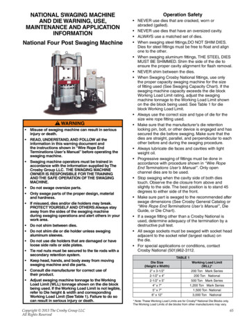
Special Issue - 2016International Journal of Engineering Research & Technology (IJERT)ISSN: 2278-0181NCIMACEMT - 2016 Conference ProceedingsTable: - IITable: - Sr.no.1Force acting on crank is maximum about 7000NAssume Gear ratio is 3:1 so speed of crank shaft 400 rpmAngular Velocity Of Crank 2*3.14*400/60 41.86 rad/secHere for maximum velocity theoryAcceleration Become ZeroV wr(sinѲ ((sin2Ѳ)/2n))A w2*r(cos Ѳ ((cos2Ѳ)/n))So dv/dt 0So by that Ѳ 77.01 now by trial and error method get crank radius 90mmSo; v 13.86m/sAcceleration of crank v 2/r 3.86/0.09 165.55m/s 2Force get by this mechanismF ma 50*165.55 8280NThis much amount of force is capable for setting die.2.6.2 Design for Connecting rodDiameter204mmLength300mmStroke length240mmThickness piston head on the basis of strength,Th 3p.D 2/16ϭt 25.43mm.Since the engine is a four stroke engine, therefore the numberof working strokes per minute,n N/2 1200/2 600.And cross sectional area of the cylinder,A л D 2/4 л (206) 2/4 33312.26mm 2.Indicated Power pm .L.A.n/60 (3.15) (0.24)(33312.26)(600)/60 251840.68w 251.47kwBrake Power IP * n 251.84*0.8 201.47kw.2.6.4 Design for cylinderFIGURE 4: Connecting rodTable: - IIISr.no.DiameterlengthStroke length194mm455mm240mmFIGURE 6: CylinderTable: - VNow, area of the section:A 2(4t*t) 3t*t 11t 2.Ixx 1/12[4t(5t) 3- 3t*(3t) 3] 419/12t 4Iyy 2*1/12 * t(4t) 3 1/12 * 3t * t 3 131/12t 4Ixx/Iyy 419/12 * 12/131 3.2.Since, the connecting rod is designed by taking the force onthe connecting rod (Fc) equal to the maximum force on thepiston (FL) due to gas pressure, therefore,Fc FL л D 2/4 * p л(94) 2/4*3.15 21849.219N.2.6.3. Design for mHere; power 5000wEfficiency 80%I.P B.P / Efficiency 5000/0.8 6250w.For Diameter of cylinder;I.P Pm. l. A. n/606250 0.35 * 1.5 D * лD 2 * 600/ 60D 206mm.2.6.5 Design for HammerTable: - VISr.no.DiameterlengthMass of Hammer1200mm300mm60kgFIGURE 5: PistonVolume 4, Issue 10Published by, www.ijert.org3
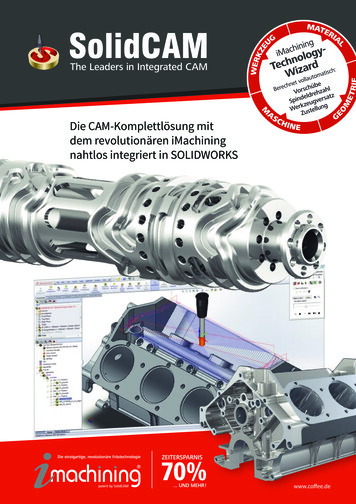
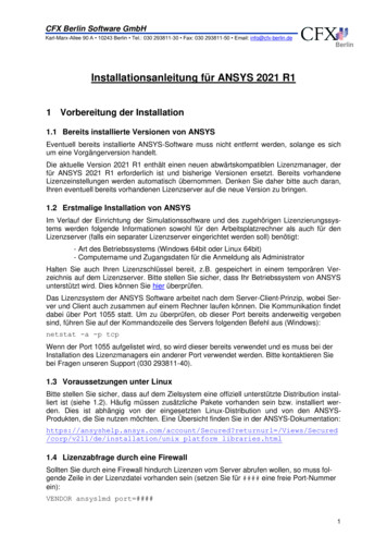
Special Issue - 2016International Journal of Engineering Research & Technology (IJERT)ISSN: 2278-0181NCIMACEMT - 2016 Conference ProceedingsThe above diagram represents the mechanism of Pistoncylinder mechanism. Forging presses collectively allow a ramthat moves in a vertical direction to exert a squeezing actionon the work piece.III. RESULT AND DISCUSSION3.1 Analysis of MechanismFIGURE 7: HammerForce obtained by this hammer;Acceleration 147 m/s2Force m*a 60* 147 8820 NTherefor by using this mechanism we obtained 8820Namount of force which is capable to set the die.2.6.6 Demonstration of Piston Cylinder MechanismFIGURE 10: Analysis of stroke length & Forces of hammerDuring the analysis between stroke length & forces ofhammer; stroke length is taken on X-axis & forces of hammeron Y-axis. In the graph stroke length range taken as ( 800 –1100mm) & forces of hammer range taken as (400N –1100N). So by analysis we can determined that as strokelengthincreases the forces obtained by hammer alsoincreases which is clearly indicate in graph. Due to thatforging hammer is continuously working as a mechanism ofpiston & cylinder and the load can be carry forward formovement of rod & hammer.FIGURE8: Piston cylinder MechanismFIGURE 11: Analysis between stroke length &TimeFIGURE 9: Modelling of Piston cylinderMechanismVolume 4, Issue 10Published by, www.ijert.org4
Special Issue - 2016International Journal of Engineering Research & Technology (IJERT)ISSN: 2278-0181NCIMACEMT - 2016 Conference ProceedingsIn the analysis on X-axis time is mentioned & o Y-axis strokelength is mentioned. During the time taken is (0-20min) &stroke length taken between (400-700mm).When the crankrotates at particular speed in the piston-cylinder mechanismconnecting rod inside cylinder with having hammer attachedin it. During analysis from the graph 1 stroke taken equal to150mm.So to complete 1 stroke it contains 11 sec which isclearly indicates in graph. Therefore by using piston-cylindermechanism to complete each stroke 11 sec is required.IV.CONCLUSIONV. REFERENCES[1][2][3][4]This paper carries on the die setting time through the analysisof piston cylinder mechanism. By the analytic calculation ofpiston cylinder mechanism productivity & accuracy of theforging parts is accrue. Through that calculation of this abovemention mechanism it is clearly indicates of complete onestroke of the striker in forging industries they required 80 secand at the another side using the piston cylinder mechanismtime required to complete one stroke is 11sec. Therefore timerequired to set the die is very much more as compared topiston cylinder mechanism. In the mechanism a combinationof ram, hammer, striker are used to increasing a pressure on aVolume 4, Issue 10work piece and solves the impact problem of additional diesetting time, less forging defects and better product quality.[5][6]Study of the mechanics of closed die forging by T.Altan, H.J.Henning,and A.M.Salroff of Battelle memorial Institute Columbus, Ohio 43201,ArmyMaterial & Mechanics research center in November 15, 1969.Slider-crank Mechanism for demonstration & experiments by EbenCob, Eric Brigham, Chris Destefano & Zacharchy Killoy at April 25,2013.Billet sorting mechanism for reducing the rejection rate in forgingoperation by A.D.Gundka, A.D.Jadhav, A.L.Kirad, J.S.Dimble fromJSPM’S Rajarshi school of engineering & research, Pune, India411041.vol.2,Issue 1,pp:(36- 47), Month:April 2015 – September 2015.Design & Key technology research of the hydraulic system of largescale Accumulator Blow Molding Machine by Wei – Min , Meng –deZhou, Young Xeu, Bao – rong Bal , from faculty of Mechanical &Automation, Liaoning University of Technology, Jinzhou121001,China overhaul centre ,Lingyan Iron & steel co.,LTD.,Chaoyang,122500,China.Mr. Rahul .R. Joshi, Prof .G.R.Naik, “Reduction in setting time”, inInternational Journal of Modern Engineering Research (IJMER).vol2,Issue:1, January – February 2012; pp – 442 -444.Published by, www.ijert.org5
8 Total time required for setting of die 2hrs & 45 min 2.5 Detail Description of die setting time are as follows:- First for new die setting procedure; die is heated on the ground at temperature of (100 - 125 C) for proper setting on hammer up to 15-20min.After that with the help of striker