Transcription
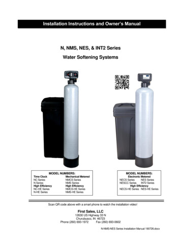
Installation Instructions and Owner’s ManualN, NMS, NES, & INT2 SeriesWater Softening SystemsMODEL NUMBERS:Time ClockNC SeriesN SeriesHigh EfficiencyNC-HE SeriesN-HE SeriesMODEL NUMBERS:Mechanical MeteredNMCS SeriesNMS SeriesHigh EfficiencyNMCS-HE SeriesNMS-HE SeriesElectronic MeteredNECS SeriesNES SeriesNESCC SeriesINT2 SeriesHigh EfficiencyNECS-HE Series NES-HE SeriesScan QR code above with a smart phone to watch the installation video!First Sales, LLC12630 US Highway 33 NChurubusco, IN 46723Phone (260) 693-1972Fax (260) 693-0602N-NMS-NES Series Installation Manual 190726.docx
Table of ContentsPre-installation InstructionsPage 2Installation InstructionsPage 4Brine TankPage 5Bypass ValvePage 5N, NC & N-HE Time Clock Timer SettingPage 7NMS, NMC & NMS-HE Meter SettingPage 9NECS, NES, NESCC, NES-HE, INT2 Series ProgrammingPage 10Unit Model SpecificationsPage 12Component Parts Breakdown & ListPage 14N, NC & N-HE Control Valve BreakdownPage 15N, NC & N-HE Control Valve Parts ListPage 16NMS, NMCS & NMS-HE Control Valve BreakdownPage 17NMS, NMCS & NMS-HE Control Valve Parts ListPage 18NECS, NES, NESCC, NES-HE, INT2 Control Valve BreakdownPage 19NECS, NES, NESCC, NES-HE, INT2 Control Valve Parts ListPage 20TroubleshootingPage 21Ten Year Limited WarrantyPage 231
Pre-installation InstructionsDescription of the water softener systemThis water softener system includes a brine (salt) tank and a resin (media) tank with a backwashing controlvalve. Incoming water flows into the control valve and is directed down through the ion exchange softeningresin. This resin exchanges the hardness ions for softer ions. The softened water then returns to the controlvalve where it is directed into the service lines.Periodically the control valve will go through a regeneration cycle. The frequency of this regeneration processwill depend on the size of water softener, incoming water quality and amount of water used. This cycle isfactory preset to begin at 2:00 A.M. At this time the control valve will draw the brine solution out of the salt tankand flush both the accumulated hardness and excess salt to the drain. The control valve will then put freshwater back into the salt tank to make brine for the next regeneration cycle.Water QualityThe water should be tested to determine the concentration, or levels of the items listed below:Hardness - Hardness in drinking water is defined as those minerals that dissolve in water having apositive electrical charge (cations). The primary components of hardness are calcium (Ca ) andmagnesium (Mg ) ions. But dissolved iron (Fe ) and manganese (Mn ) also contribute to total“adjusted” hardness. Hardness produces scale, soap scum and white mineral deposits which shortenthe life of water using appliances, plumbing and fixtures. Water that has less than 1 grain of hardness isconsidered to be “soft” water.pH - A measurement of the acidity of the water. pH is reported on a scale from 0 to 14. Neutral water has a pHof 7.0, lower values indicate acidic water. If your pH is below 6.8 you may consider installing an acid neutralizerbefore the water softener to elevate the pH.Iron - A naturally occurring metallic element. Iron levels in excess of 0.3 milligrams/liter (mg/l) combine withoxygen causing orange or red (rust) stains on plumbing fixtures. Iron exists in some water sources in clearwater (ferrous) state, red water (ferric) state or bacterial form. Iron levels that exceed 2.0 mg/l require specialion exchange resin for reduction, or if bacterial or ferric (red water) iron is present or iron level exceeds 4.0 mg/l,an iron filter should be installed ahead of this water softener.Manganese - A naturally occurring metallic element. Manganese levels as low as 0.05 milligrams/liter (mg/l)can combine with oxygen to cause dark brown or black staining on fixtures. Additionally, manganese can causean odor in the water similar to a “rotten egg” smell. This water softener may reduce manganese as well as iron;however, an iron filter may be required in some cases.Tannin - A naturally occurring humic acid. Tannin is caused by water passing through decaying vegetation.Coffee and Tea are prime examples of tannin in water. Tannin levels as low as 0.5 milligrams per liter cancause a yellow discoloration in water. Consult your dealer for a system designed to remove both tannin andhardness.Hydrogen Sulfide - A naturally occurring gas. Hydrogen sulfide, more commonly referred to as sulfur gas,causes a distinct odor similar to “rotten eggs.” Due to its gaseous nature, hydrogen sulfide must be tested at thewell site within 1 minute of drawing the sample. If sulfur is present additional equipment will be required. An airinjecting iron filter can typically treat up to 2 milligrams per liter of sulfur gas.2
Pre-installation Instructions (cont.)Location ConsiderationsThe proper location to install the water softener system will ensure optimum performance andsatisfactory water quality. The following factors should be considered in selecting the location of the equipment.1. The water softener should be installed after the pressure tank on a private well system or after thewater meter on municipal water. Operating pressure of the softener must be limited to within 30 –100 psi range.2. The water softener should be installed as close as possible (preferably within 15’) to an adequatefloor or laundry drain capable of handling the backwash cycle volume and flow rate (refer to unitspecifications).3. All water conditioning equipment should be installed prior to the water heater. Water temperaturesexceeding 100 F can damage the internal components of the control valve and filter tank. Installwith at least 10’ of pipe before the water heater to prevent thermal damage to the equipment. Anexpansion tank may need to be installed in the line to the water heater in order to allow for thermalexpansion and comply with local plumbing codes.4. The water softener should not be subject to freezing temperatures.5. Ensure that any cartridge or in-line type filter installed prior to the water softener does not restrictthe water flow and pressure available for backwash and interfere with normal operation.6. Appliances requiring extended periods of continuous or high flow water use (i.e. geothermal heatpumps, swimming pools, lawn irrigation, outside hose bibs, etc.) should bypass the water softener.(see installation diagram Fig. 1).7. Ground straps (shown in Figure 1) are only necessary when the home’s electrical system utilizesthe metal piping as the systems ground. To maintain the ground jumper wiring must be installedaround non-metal connectors or pipe (plastic) if it is used for softener installation.Grounding Straps10’ Minimum DistanceSoftenedCold WaterHardIron-Free WaterUntreated WaterSoftenedHot WaterExpansion TankInlet fromwatersupplyWater HeaterWater SoftenerIron Filter w/ couplingcheck valve installed(if required)FIGURE 1: Typical Installation3Pressure Tank(well system only)
Installation InstructionsSTEP 1:Carefully remove all components from packaging. DO NOT DISCARD PACKAGING until allwater softener components and fittings have been located.STEP 2:Use clips and screws provided and attach bypass valve to the inlet/outlet of the control valve.See figure 2 below.IMPORTANT: Mechanical metered (NMS Series) units require the installer to insert the meter cable intothe top of the meter module.N, NC, N-HE, & NC-HE(Time Clock)NMS, NMCS, NMS-HE, & NMCS-HE(Mechanical Metered)OUTINBYPASSIN SERVICEPOSITIONRETAINER CLIPSDRAIN ELBOWELBOW LOCKNG CLIPMETER MODULECONTROL VALVENECS, NES, NESCC, NES-HE, & INT2(Electronic Metered)FIGURE 2: Top View of Control ValveSTEP 3:Place unit at desired installation position. DO NOT plug into electrical outlet at this time(see STEP 15 on page 6 or see STEP 10 on page 5). DO NOT put salt in the brine tank atthis time (see STEP 14 on page 6).STEP 4:Shut off water at main supply. Relieve pressure by opening nearest faucet. On private wellsystems, turn off power to pump and drain pressure tank. SHUT OFF POWER OR FUELSUPPLY TO WATER HEATER.STEP 5:Cut main supply line as required to fit plumbing to inlet and outlet of bypass valve. DO NOTPLUMB INLET AND OUTLET BACKWARDS. Piping should be supported. Do not applyheat to any fitting attached to the bypass or control valve.STEP 6:Use polyethylene drain line tubing provided (NO VINYL TUBING) to run drain line from controlvalve discharge fitting to floor drain or sump pit capable of handling the backwash rate of thesoftener (refer to specifications and flow rate on page 12). DISCHARGE END OF THEDRAIN LINE MUST BE FIRMLY SECURED! There must be an air gap at the end of thedrain line to prevent siphoning of waste water and meet plumbing code. Total length of drainline should be 15’ or less. AVOID OVERHEAD DRAINS.4
Installation Instructions (cont.)STEP 7:Connect one end of the 3/8” brine line to the control valve quick connect fitting. Insert the otherend of the brine line through the hole in the brine tank and into the quick connect fitting on thesafety brine valve. Remove the quick connect collet retainer clip (if included) before insertingthe brine line into each fitting, press the tube in very firmly and replace the retainer clip behindthe collet. NOTE: THE BRINE TUBING SHOULD BE INSERTED 5/8” INTO THE FITTING.DO NOT PUT SALT INTO THE BRINE TANK AT THIS TIME.Brine Lineto Control ValveBrine Refill ElbowSafety BrineValveBrine TankOverflow ElbowBrineOverflowDrain Line(Not included)To Floor DrainSafety FloatSalt PlatformBrine WellAir CheckFIGURE 3: Brine Tank ComponentsSTEP 8:Install overflow tubing from overflow elbow on brine tank to floor drain. Tubing must be lowerthan overflow elbow at all times. DO NOT CONNECT DRAIN LINE FROM SOFTENERCONTROL VALVE TO BRINE TANK OVERFLOW. DO NOT CONNECT BRINE TANKDRAIN LINE TO THE SOFTENER DRAIN LINE.STEP 9:Place bypass valve in the “Bypass” position (refer to Figure 4 below). Open main supply valveor turn on power to pump on private well systems.FIGURE 4: Stainless Steel Bypass Valve OperationSTEP 10:For all models except NES Series rotate the Manual Regeneration knob (see Fig. 5, page 7 orFig. 6, page 9) clockwise to the “Backwash” position.For the NES Series plug transformer into an un-switched electrical outlet and attach the powercord into the control valve. Then press and hold down the center “ADVANCE” button for 5seconds and release after “GO TO BW” appears on the screen (see Fig. 7, page 10). Waituntil the valve reaches the backwash position before going to STEP 11.5
Installation Instructions (cont.)STEP 11:Refer to Figure 4 (page 5) for appropriate bypass valve operation. Rotate bypass lever ofstainless steel bypass ¼ of the way to Service allowing unit to fill slowly. Filling the mineraltank in this position will force any trapped air to the drain. Fully open bypass valve to the“Service” position.STEP 12:Add enough water to the brine tank to a level approximately 1” above the salt grid or 5” abovethe bottom of the brine tank if no salt grid is included.STEP 13:For N & NMS Series, rotate the Manual Regeneration knob to the “Brine Rinse” position.Continue slowly turning the knob until resistance is felt and you hear 3 clicks. Verify that thewater level in the brine tank is dropping. Allow water level to drop below the salt grid beforecontinuing (if applicable). If the water level does not drop, refer to page 23 for Troubleshooting.For the NES Series press the center “ADVANCE” button and the control valve will go to thebrine draw position. Verify that the water level in the brine tank is dropping. Allow water levelto drop below the salt grid before continuing. If the water level does not drop, refer to section 8of Troubleshooting.STEP 14:Fill the brine tank with water softener salt.STEP 15:Plug the softener into an un-switched electrical outlet, if not done previously.STEP 16:For N & NMS Series rotate the Manual Regeneration knob to the “Rapid Rinse” position andallow the regeneration to complete automatically.The NES Series should be advanced by the center “ADVANCE” button to the fast rinseposition and allow the regeneration to complete automatically.STEP 17:Check for leaks and correct as necessary.STEP 18:Turn power or fuel supply back on to water heater.STEP 19:Set the current time of day on the timer (note AM and PM) (refer to Fig. 5, Fig. 6, or Fig. 7,depending on the model number).STEP 20:Set the regeneration frequency (refer to Fig. 5, Fig. 6, or Fig. 7, depending on the modelnumber). The NMS and NES Series units determine frequency based on gallons used.6
N, NC & N-HE Series Time Clock Setting InstructionsFIGURE 5: Front of Time Clock Timer AssemblyHow to set Time of Day:1. Press and hold the red button to disengage the 24 hour gear.2. Turn the large 24 hour gear until the actual time of day is at the time of day arrow.3. Release the red button to again engage the 24 hour gear.How to set the Days of Regeneration:1. Calculate the Adjusted Hardness by multiplying the iron concentration (ppm) by 3 and adding tothe water hardness test results.Example:Hardness 25 gpg (grains per gallon)Iron 1.0 ppm (part per million)Adjusted Hardness 28 gpg[25 (3 x 1.0)]25 3 282. Refer to the appropriate table for your water softener model number (pages 8 and 9) to determinehow many TIMES in a 12 day cycle the softener should regenerate. If the adjusted hardness fallsbetween two numbers on the chart always use the higher number (never round down).Example:Water Softener ModelN-13 people in familyAdjusted hardness28 gpgResult: Set softener to regenerate 4 TIMES in 12-day cycle (once every 3 days)3. Rotate the skipper wheel until the number 1 is at the red pointer. Each number represents a day.The number by the red pointer is tonight.4. Slide the metal tabs outward on the desired days of regeneration.How to Manually Initiate a Regeneration Cycle:1. Grab the manual regeneration knob and turn clockwise SLIGHTLY.2. The drive gear will engage the regeneration knob which will make a complete revolution and returnto the “Service” position after the regeneration cycle.7
N, NC & N-HE Series Time Clock Setting Instructions (cont.)Adjusted Hardness -- Grains per 12346652346662346724402TABLE 1: Model Number N-1, NC-1 & N-1-HEAdjusted Hardness -- Grains per 02TABLE 2: Model Number N-1.5, N-1.5-HEAdjusted Hardness -- Grains per 2344681234669123461023466TABLE 3: Model Number N-2, N-2-HE8
NMS, NMCS, NMS-HE Series Meter Setting InstructionsFIGURE 6: Front of Mechanical Meter Timer AssemblyHow to set Time of Day:1. Press and hold the red button to disengage the 24 hour gear.2. Turn the large 24 hour gear until the actual time of day is at the time of day arrow.3. Release the red button to again engage the 24 hour gear.How to set the Frequency of Regeneration:1. Calculate the Adjusted Hardness by multiplying the iron concentration (ppm) by 3 and adding tothe water hardness test results.Example:Hardness 25 gpg (grains per gallon)Iron 1.0 ppm (part per million)Adjusted Hardness 28 gpg[25 (3 x 1.0)]25 3 282. Lift the “People Dial” on the gallon setting wheel.3. Rotate the “People Dial” until the number of people in the household is aligned with the adjustedwater hardness.4. Release the “People Dial” and ensure that it reengages the gallon wheel.How to Manually Initiate a Regeneration Cycle:1. Grab the manual regeneration knob and turn clockwise SLIGHTLY.2. The drive gear will engage the backwash knob which will make a complete revolution and return tothe “Service” position after the regeneration cycle.9
NECS, NES, NESCC, NES-HE, INT2 Series ProgrammingAdvance ButtonFIGURE 7: Front of Electronic Meter Timer AssemblySET BUTTON1. Press and hold “Set Button” for 5 seconds to enter Programming Mode.2. When valve is in Programming Mode, press “Set Button” to confirm setting and advance to nextmenu option.ADVANCE BUTTON1. Press and hold “Advance Button” for 5 seconds to initiate an immediate regeneration cycle.2. Press and release “Advance Button” during a regeneration cycle to immediately advance the valveto the next step in the regeneration process.3. When the valve is in Programming Mode, press the “Advance Button” to move the cursor.UP BUTTON1. When the valve is in the Programming Mode, press “Up Button” to adjust setting.10
NECS, NES, NESCC, NES-HE Series ProgrammingEnter Programming Mode:Press and Hold the SET Button for 5 seconds.Use Up Button to set current hourUse Up Button to set current minuteUse Up Button to set AM/PMUse Up Button to set ADJUSTED HardnessExit Programming Mode11
SpecificationsUNIT MODEL NUMBERDESCRIPTION3MEDIA VOLUME, ftCAPACITY, grains3Factory Salt @ 9 lb/ft3Max. Salt @ 15 lb/ftSERVICE FLOW RATES, gpm3Continuous (3 gpm/ ft )3Service (8 gpm/ ft )Peak*BACKWASH & RAPID RINSE, gpmBRINE FILL, gpmSERVICE PIPE SIZE, inchesFor 1” replace “–S” w/ “-1S” in model #TOTAL WATER USED, gallonsDIMENSIONS, inchesMineral Tank (diameter x height)Brine Tank (diameter x height)Overall (depth x width x height)APPROXIMATE SHIP WT., lbs ¾”814154.00.5¾”738655748712813010 x 3512 x 3413 x 22 x 437010 x 3512 x 3413 x 21 x 43848 x 4414 x 3415 x 22 x 52779 x 4814 x 3418 x 27 x 568710 x 5414 x 3418 x 28 x 6211412 x 4818 x 3318 x 30 x 5614513 x 5418 x 3318 x 32 x ¾”86748712810 x 3512 x 3413 x 23 x 43869 x 4814 x 3418 x 27 x 568610 x 5414 x 3418 x 28 x 6211112 x 4818 x 3318 x 30 x 56142UNIT MODEL NUMBERDESCRIPTION3MEDIA VOLUME, ftCAPACITY, grains3Factory Salt @ 6 lb/ft3Max. Salt @ 15 lb/ftSERVICE FLOW RATES, gpm3Continuous (3 gpm/ ft )3Service (8 gpm/ ft )Peak*BACKWASH & RAPID RINSE, gpmBRINE FILL, gpmSERVICE PIPE SIZE, in.For 1” replace “–S” w/ “-1S” in model #TOTAL WATER USED (gallons)DIMENSIONS, inchesMineral Tank (diameter x height)Brine Tank (diameter x height)Overall (depth x width x height)APPROXIMATE SHIP WT., lbsGENERAL REQUIREMENTS:NOTES:Water TemperatureWater PressureElectrical RequirementsElectrical Current Draw33 F - 100 F25 - 100 psi110v/60hz0.5 amps*The control valve can handle flow rates greater than the peak flowrates shown above. What matters is the flow rate the unit canhandle and still provide zero water hardness.12
Specifications (cont.)DESCRIPITION3MEDIA VOLUME, ftCAPACITY, grains3Factory Salt @ 9 lb/ft3Max. Salt @ 15 lb/ftSERVICE FLOW RATES, gpm3Continuous (3 gpm/ft )3Service (8 gpm/ft , 15psi drop)Peak*BACKWASH & RAPID RINSE, gpmBRINE FILL, gpmSERVICE PIPE SIZE, in. (cm)For 1” replace –S w/ -1S in model #FACTORY REGENERATION SETTINGSDefault size settingRegen after capacity used (x1000)Backwash (minutes)Brine Draw (minutes)Fast Rinse (minutes)Brine Refill (minutes)TOTAL WATER USED, gallonsDIMENSIONS, inchesMineral Tank (diameter x height)Brine Tank (diameter x height)Overall (depth x width x height)APPROXIMATE SHIP WT., lbs.UNIT MODEL 468LARGE2886066112OFF408606811410 x 3512 x 3413 x 22 x 437110 x 3512 x 3413 x 21 x 43868 x 4414 x 3415 x 22 x 52719 x 4814 x 3418 x 27 x 568610 x 5414 x 3418 x 28 x 6211112 x 4818 x 3318 x 30 x 5614213 x 5418 x 3318 x 32 x 621681DESCRIPTION3MEDIA VOLUME, ft (liters)CAPACITY, grains3Factory Salt @ 9 lb/ft3Factory Salt @ 6 lb/ft3Max. Salt @ 15 lb/ftSERVICE FLOW RATE, gpm3Continuous (3 gpm/ft )3Service (8 gpm/ft , 15psi drop)Peak*BACKWASH & RAPID RINSE, gpmBRINE FILL, gpmSERVICE PIPE SIZE, in. (cm)For 1” replace –S with -1S in model #FACTORY REGENERATION SETTINGSDefault size settingRegen after capacity used (x1000)Backwash (minutes)Brine Draw (minutes)Fast Rinse (minutes)Brine Refill (minutes)TOTAL WATER USED, gallonsDIMENSIONS, inchesMineral Tank, diameter x heightBrine Tank, depth x width x heightOverall, length x width x heightAPPROXIMATE SHIP WT., lbs.GENERAL REQUIREMENTS:NOTES:UNIT MODEL 6454246OFF246506362OFF2886064110SMALL12645434310 x 35CABINET13 x 22 x 458610 x 44CABINET13 x 22 x 5013510 x 3513 x 13 x 3513 x 23 x 43869 x 4815 x 15 x 3515 x 24 x 568610 x 5415 x 15 x 3515 x 25 x 6211112 x 4818 x 3318 x 27 x 5614210 x 3513 x 13 x 3513 x 28 x 4490Water Temperature33 F - 100 FWater Pressure25 - 100 psiElectrical Requirements110v/60hzElectrical Current Draw0.5 amps*The control valve can handle flow rates greater than the peak flow rates shown above. What matters is the flow rate theunit can handle and still provide zero water hardness.13
Component Parts Breakdown123647958Ref#Description2345678Timeclock Valveless bypassMech. MeteredValve less bypassElect. MeteredValve less bypassMineral TankDistributorResin¼” X 1/8” GravelOverflow FittingSafety Brine ValveSalt Platform9Brine Tank Assy.1Ref#UNITNC-0.75-SNMCS-0.75-SNECS-0.75-SNC-1 Vlv AssyL/BPNMCS-1 VlvAssy L/BPNEC-1 Vlv AssyL/BPNC-1-SNMCS-1-SNECS-1-SNC-1 Vlv AssyL/BPNMCS-1 VlvAssy L/BPNE-1 Vlv AssyL/BPN-1-SNMS-1-SNES-1-SN-1 Vlv AssyL/BPNM-1 VlvAssy L/BPNE-1 VlvAssy L/BPN-1.5-SNMS-1.5-SNES-1.5-SN-1.5 VlvAssy L/BPNM-1.5 VlvAssy L/BPNE-1.5 VlvAssy L/BPN-2-SNMS-2-SNES-2-SN-2 Vlv AssyL/BPNM-2 VlvAssy L/BPNE-2 VlvAssy L/BPN-2.5-SNMS-2.5-SNES-2.5-SN-2.5 Vlv AssyL/BPNM-2.5 VlvAssy L/BPNE-2.5 VlvAssy TP1354GRD100S-48(1.5) H05PQC20D100S-48(2) H05PQC20D100S-48(2) H05PQC20D100S-54(3) H05PQC20D100S-48(4) H05PQC20D100S-54(5) H05P(1.5) 1-S-HENECS-1-S-HEN-1-HE Vlv AssyL/BPNM-1-HE VlvAssy L/BPNEC-1-HE VlvAssy L/BPN-1-S-HENMS-1-S-HENES-1-S-HEN-1-HE VlvAssy L/BPNM-1-HE VlvAssy L/BPNE-1-HE VlvAssy L/BPN-1.5-S-HENMS-1-S-HENES-1.5-S-HEN-1.5-HE VlvAssy L/BPNM-1.5-HE VlvAssy L/BPNE-1.5-HE VlvAssy L/BPN-2-S-HENMS-2-S-HENES-2-S-HEN-2-HE VlvAssy L/BPNM-2-HE VlvAssy L/BPNE-2-HE VlvAssy SINT2-S-NA--NA--NA--NA--NA--NA-NEC-1 VlvAssy L/BPNE-1.5 VlvAssy L/BPINT2-S VlvAssy L/BPMTP1248GRMTP1035GRMTP1044GRMTP1035GR2Timeclock Valveless bypassMech. MeteredValve less bypassElect. MeteredValve less bypassMineral 00S-48D100S-48D100S-4845678Resin¼” X 1/8” GravelOverflow FittingSafety Brine ValveSalt Platform(1.5) UHE05PQC20(2) UHE05PQC20(3) UHE05PQC20(4) UHE05PQC20(2) H05PQC20(2.5) H05PQC20(2) G14BTSG14BTSG18SQ9Brine Tank BINETUNIT-NACABINETUNIT114BTSG12BT1234ASSY
N, NC, N-HE Time Clock Control Valve Breakdown15
N, NC, N-HE Time Clock Control Valve Parts ListREF #Part 00-41Coupling, Adapter S/ASSY60040SSBypass Valve, Stainless, ¾” NPT (Standard)60041SSBypass Valve, Stainless, 1” NPT (Optional, use -1S suffix instead of -S)118743-1Motor, 120v/60hz, 1/30 RPM213304O-Ring, Distributor, -121312281O-Ring, Tank, -338G45678DescriptionPower Head, Time ClockPiston AssemblySeal and Spacer KitInjector and Drain Housing Assy, Blank DLFC, #1 Injector, 0.5 GPM BLFCBrine Stem Assembly10914-1Injector Throat, #1, White (NC-1, N-1, N-1-HE, N-1.5, N-1.5-HE)10914-2Injector Throat, #2, Blue (N-2, N-2-HE)10227Injector Screen10913-1Injector Nozzle, #1, White (NC-1, N-1, N-1-HE, N-1.5, N-1.5-HE)10913-2Injector Nozzle, #2, Blue (N-2, N-2-HE)13303O-Ring, -02112088Flow Control Washer, 2.4 GPM (N-1, N-1-HE)12089Flow Control Washer, 3.0 GPM (NC-1, N-1.5, N-1.5-HE)12091Flow Control Washer, 4.0 GPM (N-2, N-2-HE)9NE-DRAIN ELBDrain Elbow, Quick Connect x ½” barbed10NE-DRAIN CLIPQuick Release Clip, Drain Elbow11NE-CON ORG1214105Bypass Valve Seal, Single Lever13NOTSHOWN18280-02Top Screen, Bayonet Style, Red13753-02Black Front CoverConnector O-Ring16
NMS, NMCS, NMS-HE Metered Control Valve Breakdown17
NMS, NMCS, NMS-HE Metered Control Valve Parts ListREF #Part NumberDescriptionANMS-PHPower Head, Mechanical MeteredB60102-00Piston AssemblyC60125D60084-0102NMSE60032Brine Stem AssemblyF60088Meter Module, Right Angle, Standard RangeSeal and Spacer KitInjector and Drain Housing Assy, Blank DLFC, #1 Injector, 0.5 GPM BLFC60040SSBypass Valve, Stainless, ¾” NPT (Standard)60041SSBypass Valve, Stainless, 1” NPT (Optional, use -1S suffix instead of -S)118743-1Motor, 120v/60hz, 1/30 RPM213304O-Ring, Distributor, -121312281O-Ring, Tank, -338G4567810914-1Injector Throat, #1, White (NMCS-1, NMS-1, NMS-1-HE, NMS-1.5, NMS-1.5-HE)10914-2Injector Throat, #2, Blue (NMS-2, NMS-2-HE)10227Injector Screen10913-1Injector Nozzle, #1, White (NMCS-1, NMS-1, NMS-1-HE, NMS-1.5, NMS-1.5-HE)10913-2Injector Nozzle, #2, Blue (NMS-2, NMS-2-HE)13303O-Ring, -02112088Flow Control Washer, 2.4 GPM (NMS-1, NMS-1-HE)12089Flow Control Washer, 3.0 GPM (NMCS-1, NMS-1.5, NMS-1.5-HE)12091Flow Control Washer, 4.0 GPM (NMS-2, NMS-2-HE)9NE-DRAIN ELBDrain Elbow, Quick Connect x ½” barbed10NE-DRAIN CLIPQuick Release Clip, Drain Elbow11NE-CON ORG121410513NOTSHOWN18280-02Top Screen, Bayonet Style, Red13753-02Black Front CoverConnector O-RingSeal, Single Lever Bypass Valve18
NECS, NES, NESCC, NES-HE Metered Control Valve Breakdown19
NECS, NES, NESCC, NES-HE Metered Control Valve Parts ListREF #Part NumberDescriptionANE-PHPowerhead, MeteredBNE-FCFront Panel and Circuit Board AssemblyC60102-NESD60125E60084-0123NESF60032Brine Stem AssemblyGEM-1Meter Module (includes cable)H60040SS¾” Stainless Steel Bypass Valve1423492NE-TRANS313304O-Ring, Distributor, -121412281O-Ring, Tank, -33856789Piston AssemblySeal and Spacer KitInjector and Drain Housing Assy, 2.4 gpm DLFC, #1 Injector, 1 GPM BLFCMotor, 24v/60hz, 2 RPMTransformer, 110v Input--24v Output10914-1Injector Throat, #1, White (for NE-1, NEC-1 and NE-1.5)10914-2Injector Throat, #2, Blue (for NE-2)10227Injector Screen10913-1Injector Nozzle, #1, White (for NE-1, NEC-1 and NE-1.5)10913-2Injector Nozzle, #2, Blue (for NE-2)13303O-Ring, -02112088Flow Control Washer, 2.4 GPM (for model NE-1)12089Flow Control Washer, 3.0 GPM (for model NEC-1 and NE-1.5)12090Flow Control Washer, 3.5 GPM (for models NE-2 Only)10NE-DRAIN ELBDrain Elbow, Quick Connect x ½” barbed11NE-DRAIN CLIPQuick Release Clip, Drain Elbow12NE-CON ORG131410514NE-CLIPSClips and screws set for NES & FES1518280-02Top Screen, Bayonet Style, RedConnector O-RingBypass Valve Seal, Single Lever20
TroubleshootingPROBLEMCAUSEA. Electrical service to unit has beeninterrupted1. Softener fails to regenerateB.C.D.A.Meter cable not inserted into meterDefective timer motorFaulty meter assemblyBypass valve is openB. No salt in brine tankC. Brine tank overfilled with waterD. Insufficient water flowing into brinetankE Leak at distributor tube2. Softener delivers hard waterF. Internal valve leakG. Softener not regeneratingH. Slow leak in plumbing that is notregistered by the meter IE drippingfaucetI. Softener resin fouled by iron3. Unit uses too much saltA. Improper salt settingB. Excessive water in brine tankC. Leak in plumbing that is sufficient tobe registered by the meter IErunning toiletA. Softener too small for application4. Loss of water pressureB. Foreign material buildup in watersoftenerA. Air in water system5. Loss of resin through drain lineB. Drain line flow control is too largeC. Mineral tank is overfilledA. Softener is installed backwards6. Loss of resin into service lineB. Hot water has backed up into thesoftener and melted componentsC. Broken distributor basketD. Gravel underbed shifted to one side21SOLUTIONA. Ensure permanent electrical serviceto unit (switch, circuit breaker, plug,etc.)B. Insert meter cable into meterC. Replace timer motorD. Replace meter assemblyA. Close bypass valveB. Add salt to brine tank and maintainsalt level above water levelC. See Problem # 8 belowD. Check brine tank fill time and cleanbrine line flow controlE. Check length of distributor tube andcondition of pilot tube o-ringF. Replace piston and seals/spacer kitG. See Problem # 1 aboveH. Eliminate sources of slow leaksI. Manually regenerate with a strongsolution of resin cleaner for iron orre-bed the softenerA. Correct salt settingB. See Problem # 8 belowC. Eliminate sources of leaksA. Check application requirements andresize water softener as requiredB. Perform an extended backwash:1) Place unit in manual regeneration2) When backwash begins, unplugthe unit from the electrical outlet3) Allow unit to remain in backwashfor 30 minutes4) Plug unit back into electricalOutlet, allow regeneration tofinish automaticallyA. Locate source of air in system:1) Check for low water tableconditions in well2) Check for positive seal on brineline connect
1. The water softener should be installed after the pressure tank on a private well system or after the water meter on municipal water. Operating pressure of the softener must be limited to within 30 - 100 psi range. 2. The water softener should be installed as close as possible (preferably within 15') to an adequate
