Transcription
Flareless Tube Fittings Tubing Data ChartsIndexSafety WarningInside Front CoverCalculating Yield, Burst, andMaximum Allowable Working Pressures2Maximum Allowable Stress Valuesfor Material at Various Temperatures3–4Stainless Steel Calculation Factor Tables5Maximum Working/Burst PressuresCopper Seamless Tubing6304/316 Stainless Steel Seamless Tubing7254 SMO Seamless Tubing89HASTELLOY C-276 TubingMONEL 400 Tubing10Grade 2 Titanium Tubing112507 Super Duplex Stainless Steel Seamless Tubing12INCONEL 625 Tubing13INCOLOY 825 Tubing132205 Duplex Stainless Steel Seamless Tubing14Tubing Tolerances15-16DisclaimersInside Back Cover GYROLOKCRANE Instrumentation & Sampling, HOKE PO Box 4866 Spartanburg, SC 29305-4866(864) 574-7966 www.hoke.com
For Your SafetyIt is solely the responsibility of the system designer and user to select products suitable for their specific applicationrequirements and to ensure proper installation, operation, and maintenance of these products. When selecting products,the total system design must be considered to ensure safe, trouble-free performance. Material compatibility, productratings and application details should be considered in the selection. Improper selection or use of products describedherein can cause personal injury or property damage.Contact your authorized HOKE sales and service representative for information about additional sizes and special alloys.SAFETY WARNING:HOKE products are designed for installation only by professional suitably qualified licensed system installers experiencedin the applications and environments for which the products are intended. These products are intended for integrationinto a system. Where these products are to be used with flammable or hazardous media, precautions must be taken bythe system designer and installer to ensure the safety of persons and property. Flammable or hazardous media pose risksassociated with fire or explosion, as well as burning, poisoning or other injury or death to persons and/or destruction ofproperty. The system designer and installer must provide for the capture and control of such substances from any ventsin the product(s). The system installer must not permit any leakage or uncontrolled escape of hazardous or flammablesubstances. The system operator must be trained to follow appropriate precautions and must inspect and maintain thesystem and its components including the product(s) and at regular intervals in accordance with timescales recommendedby the supplier to prevent unacceptable wear or failure.
Flareless Tube Fittings Tubing Data ChartsTubing should always be fully annealed. While weldedtubing may be used with GYROLOK , inconsistencies in itsmanufacture and performance are sometimes encountered.As a result we recommend the use of seamless tubing.For proper fitting performance, the tubing surface finishshould be good, free from nicks or scratches. Do not useout of round tubing which does not easily go throughfitting components.Fitting performance is maximized when tube ends aresquarely cut, using a tubing cutter, and deburred.Design GYROLOK Flareless Tube Fittings have been carefullydesigned and manufactured to provide a wide range ofoutstanding leak-tight application capabilities. GYROLOK ratings and specifications are as follow:Pressure RatingsGYROLOK fittings are rated for working pressures higherthan the tubing recommended for use with GYROLOK .However, tubing should not be used above its maximumallowable working pressure.Maximum allowable working pressures for tubing suitablefor use with GYROLOK are identified herein. If nopressure is identified for a given size and a wall thickness,then that tube size/wall combination is not suitable for usewith GYROLOK fittings. See caution below.MaterialsGYROLOK & GYROLOK -XP fittings are availablein brass, 304 and 316 stainless steel, MONEL ,HASTELLOY , INCONEL & INCOLOY , titanium, 2205Duplex, 2507 Super Duplex and 254 SMO. Contact yourlocal HOKE distributor for further information.TubingFully annealed tubing to the specifications identifiedherein are suitable for use with GYROLOK fittings.The tubing selected, whether metallic or nonmetallicshould be compatible with the process fluid, temperatureand applications. The wall thickness selections should bebased on pressure and temperature conditions.Gas ServiceGases (air, hydrogen, nitrogen, etc.) can escape throughsmaller leak paths than liquids. As such, the reductionof surface defects (scratches) on tubing becomes moreimportant when the system media contains gases. Astubing wall thickness increases, the ability of the ferrulesto coin out imperfections increases. The use of heavierwall tubing will help the ferrules to overcome minorsurface defects that could contribute to gas leakage.HOKE recommends the following minimum wall thicknessfor tubing when system media contains gases.TUBE OD NOMINAL MINIMUM WALL TUBE OD NOMINAL MINIMUM WALL(inches)THICKNESS (inches)(inches)THICKNESS (inches)1 /83 /40.0280.0653 /167/80.0280.0831 /410.0830.0285 /160.1090.03511 /43 /81½0.1340.0351 /20.04920.180Suggested Allowable Pressure TablesFigures and tables are for reference only. HOKE makesno implication that these valves can be used for designwork. Applicable codes and practices in industry shouldbe reviewed and considered. ASME Codes are thesuccessor to and replacement of ASA Piping Codes. Forcombinations not shown, consult factory . GYROLOKVacuum RatingGYROLOK offers excellent vacuum capability. With goodquality tubing, GYROLOK fittings will be leak-tight atvacuum levels of 10 -9 torr while tested with a leakagesensitivity of 10 -9 sccs.Proper fitting performance demands that the fitting besignificantly harder than the tubing on which it is used.For example, stainless steel tubing should never exceeda maximum surface hardness of Rockwell B90, whileMONEL tubing should never exceed a maximum surfacehardness of Rockwell B75. 1
Calculating Yield, Burst, and Maximum Allowable Working PressuresMaximum allowable stress values and calculation factors are used to determine yield, burst, and maximum allowable workingpressures. HOKE has made these calculations for a variety of materials and included the results in charts beginning on page 6. Thefollowing information is presented to provide an understanding of how the numbers are derived.Formulas1. Maximum Allowable Working PressureFractional:Factor Maximum Allowable Stress Valve (psi)Metric:Factor Maximum Allowable Stress Valve (psi) 0.06895Factor Maximum Allowable Stress Value (ksi) 68.952. Calculated Yield PressureFractional:Factor Minimum Yield Strength (psi)Metric:Factor Minimum Yield Strength (psi) 0.068953. Calculated Burst PressureFractional:Factor Minimum Tensile Strength (psi)Metric:Factor Minimum Tensile Strength (psi) 0.6895See table of “Maximum Allowable Stress Values for Material at Various Temperatures” on pages 3 and 4, and the “Calculation FactorTables” on page 5.Maximum Allowable Working Pressure Calculation ExamplesThe values listed on the “CALCULATION FACTOR TABLE” are for stainless steel and may be used to determine the maximumallowable pressure, yield pressure, burst pressure or any other pressure for which a stress value is available. The CalculationFactor Tables on page 5 are based on stainless steel tubing having maximum allowable outside diameter and minimum allowablewall thickness. Stress values may be obtained from “MAXIMUM ALLOWABLE STRESS VALUES FOR MATERIALS AT VARIOUSTEMPERATURES” table or other sources. All of the charts contained herein are based on use of tubing having the “worst” toleranceconditions allowed for that particular material.Example 1Suppose that you want to know the maximum allowable workingpressure of 304 S. ST. seamless, ASTM A-213, ¼” O.D. by .035wall tubing at a temperature of 100 F. This information canbe directly obtained from the table “MAXIMUM ALLOWABLEWORKING PRESSURE – 304 STAINLESS STEEL” or calculatedas follows:Example 2Suppose that you want to know the maximum allowable workingpressure of 304 stainless steel seamless, ASTM A-213, 6mmO.D. by 1.2mm wall tubing at a temperature of 38 C. Thisinformation can be directly obtained from the table “MAXIMUMALLOWABLE WORKING PRESSURE – 304 STAINLESS STEEL”or calculated as follows:First Find the factor (K) corresponding to ¼” O.D. 0.035 wallon the “CALCULATION FACTOR TABLE”.First Find the factor (K) corresponding to 6mm O.D. 1.2mmwall on the “CALCULATION FACTOR TABLE”.K 0.2753K 0.4112Second Find the allowable stress (SA) for seamless 304 stainlesssteel tubing at 100 F on the “MAXIMUM ALLOWABLE STRESSVALUES FOR MATERIALS AT VARIOUS TEMPERATURES”.Second Find the allowable stress (SA) for seamless 304 stainlesssteel tubing at 38 C on the “MAXIMUM ALLOWABLE STRESSVALUES FOR MATERIALS AT VARIOUS TEMPERATURES”.SA 18,750 psiSA 18,750 psiThird According to “CALCULATION FACTOR TABLE”, MaximumAllowable Working Pressure (PA) Factor (K) MaximumAllowable Stress (SA) Value in psiTherefore: PA K SAPA 0.2753 18,750 psiPA 5161 psi (Max. Allowable Working Pressure at 100 F)Third According to “CALCULATION FACTOR TABLE”, MaximumAllowable Working Pressure (PA) Factor (K) MaximumAllowable Stress (SA) Value in psi 0.06895Therefore: PA K SA 0.06895PA .4112 x 18,750 psi 0.06895PA 532 bar (Max. Allowable Working Pressure at 38 C)CAUTION: Limited test data is available on certain materials, including HASTELLOY , INCONEL , 2205 Duplex, and 254 SMO. In such applications, furthertesting either by HOKE or by the user is recommended to assure fi tting suitability for the application.2
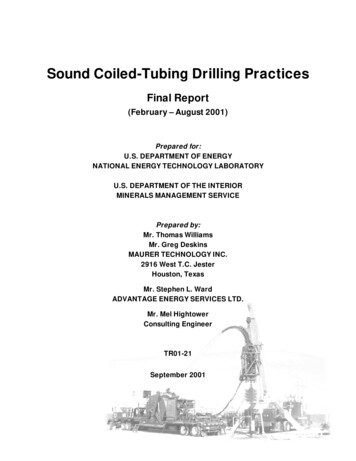
Maximum Allowable Stress Values for Materials at Various TemperaturesValues in ksi (psi ksi 1000)TEMPERATURE F 20 to 09501000105011001200125013001350140014501500Min. TensileStrength (ksi)@ 100 FMin. YieldStrength (ksi)@ 100 F C 29 to 0538566593649677704732760788815Min TensileStrength (ksi)@ 38 CMin YieldStrength (ksi)@ 38 CCOPPERSEAMLESSANNEALEDTUBING SPECASTM B-756.05.14.84.84.74.03.0TYPE 304SEAMLESSWELDEDANNEALEDANNEALEDTUBING SPECTUBING SPECASTM A-213ASTM 2.01.81.51.41.2TYPE 316SEAMLESSWELDEDANNEALEDANNEALEDTUBING SPECTUBING SPECASTM A-213ASTM .51.31.1MONEL 400SEAMLESSANNEALEDTUBING SPECASTM 14.714.714.614.211.08.0INCONEL 600SEAMLESSANNEALEDTUBING SPECASTM 0809303030302835 3
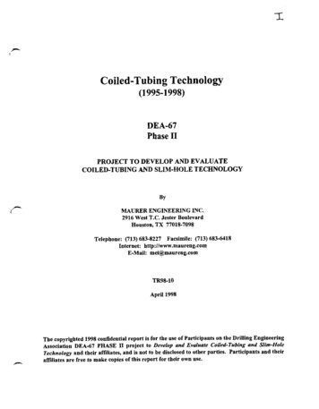
Maximum Allowable Stress Values for Materials at Various TemperaturesValues in ksi (psi ksi 1000)TEMPERATURE F C 20 to 29 to 38 32140076014507881500815Min. Tensile Min. TensileStrength (ksi) Strength (ksi)@ 100 F@ 38 CMin. YieldMin. YieldStrength (ksi) Strength (ksi)@ 100 F@ 38 CSEAMLESSSOLUTIONANNEALEDTUBING SPECASTM B-622WELDEDSOLUTIONANNEALEDTUBING SPECASTM B-626SEAMLESSSOLUTIONTREATEDTUBING SPEC.ASTM A-269SEAMLESSSOLUTIONTREATEDTUBING SPEC.ASTM A-7892507 SUPERDUPLEXSEAMLESSSOLUTIONTREATEDTUBINGSPEC. 810010094905050414144654040HASTELLOY C-276254 SMO2205 DUPLEXTITANIUM GRADE 2SEAMLESSANNEALEDTUBING SPEC.ASTM B-338WELDEDANNEALEDTUBINGSPEC. ASTMB-338Allowable stress values extracted from ASME Boiler and Pressure Vessels Code Section II Part D and ASME B31.3 Process Piping withpermission of the publisher ASME.4
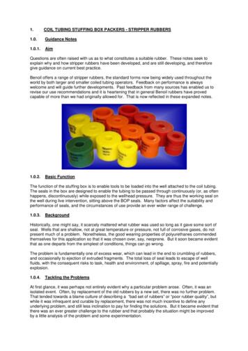
Tubing Data ChartsStainless Steel Calculation Factor TablesFor gas service, select a wall thickness that is not shaded (see Gas Service, page 1).WALL THICKNESS (inch)TUBINGO.D.(inch) 0.010 0.012 0.016 0.020 0.028 0.035 0.049 0.065 0.083 0.095 0.109 0.120 0.134 0.148 0.156 0.180 0.1881 160.3035 0.3733 0.5238 0.69101 80.4585 0.58513 160.2942 0.3791 0.5492¼0.2155 0.2753 0.4033 0.54933 80.1405 0.1781 0.2566 0.3533 0.4631½0.1316 0.1882 0.2559 0.3363 0.39225 80.1486 0.2010 0.2625 0.3050 0.3574¾0.1227 0.1654 0.2152 0.2494 0.2904 0.32357 80.1045 0.1406 0.1824 0.2110 0.2451 0.272510.1220 0.1579 0.1824 0.2115 0.23491¼0.1249 0.1440 0.1666 0.1847 0.2080 0.2318 0.2455 0.28761½0.1189 0.1374 0.1522 0.1711 0.1904 0.2015 0.2354 0.246920.0872 0.1006 0.1112 0.1248 0.1386 0.1465 0.1706 0.1787For gas service, select a wall thickness that is not shaded (see Gas Service, page L THICKNESS F
Calculated Burst Pressure Fractional: Factor Minimum Tensile Strength (psi) Metric: Factor Minimum Tensile Strength (psi) 0.6895 See table of “Maximum Allowable Stress Values for Material at Various Temperatures” on pages 3 and 4, and the “Calculation Factor Tables” on page 5. Maximum Allowable Working Pressure Calculation Examples The values listed on the “CALCULATION .