Transcription
RTB Tubing Bundles InstallationGuideHeating Solutions for Instrument and Small-DiameterProcess Lines
WARNING:Fire and shock hazard.nVent RAYCHEM heat-tracing systems must be installed correctly to ensure proper operation andto prevent shock and fire. Read these important warnings and carefully follow all the installationinstructions. To minimize the danger of fire from sustained electrical arcing if the heating cable is damagedor improperly installed, and to comply with nVent requirements, agency certifications, and thenational electrical codes, ground-fault equipment protection must be used on each heatingcable branch circuit. Arcing may not be stopped by conventional circuit breakers. Approvals and performance of the heat-tracing systems are based on the use of nVentspecified parts only. Do not substitute parts or use vinyl electrical tape. Bus wires will short if they contact each other. Keep bus wires separated. Components and cable ends must be kept dry before and during installation. The black heating-cable core and fibers are conductive and can short. They must be properlyinsulated and kept dry. Damaged bus wires can overheat or short. Do not break bus wire strands when preparing thecable for connection. Damaged heating cable can cause electrical arcing or fire. Do not use metal attachments suchas pipe straps or tie wire. Use only nVent-approved tapes and cable ties to secure the cable tothe pipe. Do not attempt to repair or energize damaged cable. Remove damaged cable at onceand replace with a new length using the appropriate nVent splice kit. Replace damagedcomponents. Re-use of the grommets, or use of the wrong grommet, can cause leaks, cracked components,shock, or fire. Be sure the type of grommet is correct for the heating cable being installed. Usea new grommet whenever the cable has been pulled out of the component. Use only fire-resistant insulation which is compatible with the application and the maximumexposure temperature of the system to be traced. To prevent fire or explosion in hazardous locations, verify that the maximum sheathtemperature of the heating cable is below the auto-ignition temperature of the gases in thearea. For further information, see the design documentation. Material Safety Data Sheets (MSDSs) are available from the nVent Customer Service Center,and at nVent.com.2 nVent.com
CONTENTS1. General Information. 41.1 Use of the Manual. 41.2 Safety Guidelines. 41.3 Electrical Codes. 41.4 Warranty and Approvals. 42. Introduction. 52.1 Product Line. 52.2 System Overview. 62.3 Tubing Bundle Catalog Number. 72.4 Bundle Materials. 73. Verify Product Selection. 83.1 Heater Type and Temperature Range. 83.2 Electrical Sizing and Run Length. 93.3 Select Components. 113.4 Select Bundle Accessories. 114. Installation. 134.1 Description. 134.2 Weights and Dimensions. 134.3 Storage. 144.4 Positioning and Support. 144.5 Uncoiling and Bending. 154.6 Electric Trace-Heating Connections. 154.7 Bundle Sealing. 174.9 Thermostat Jacket Patch. 18nVent.com 3
1. GENERAL INFORMATION1.1 USE OF THE MANUALThis installation and maintenance manual is for nVent RAYCHEM RTB Tubing Bundles systems only.For information regarding other applications, design assistance or technical support, contact yournVent representative or nVent directly.nVent899 Broadway StreetRedwood City, CA 94063USATel (800) 545-6258Fax (800) t: For the nVent warranty and agency approvals to apply, the instructions that areincluded in this manual and product packages must be followed.1.2 SAFETY GUIDELINESThe safety and reliability of any heat-tracing system depends on proper design, installation andmaintenance. Incorrect handling, installation, or maintenance of any of the system componentscan cause underheating or overheating of the pipe or damage to the heating-cable system andmay result in system failure, electric shock or fire.1.3 ELECTRICAL CODESSections 427 (pipelines and vessels) and 500 (classified locations) of the National ElectricalCode (NEC), and Part 1 of the Canadian Electrical Code, Sections 18 (hazardous locations) and62 (Fixed Electric Space and Surface Heating), govern the installation of electrical heat-tracingsystems. All heat-tracing-system installations must be in compliance with these and any otherapplicable national or local codes.1.4 WARRANTY AND APPROVALSThe RTB system uses nVent RAYCHEM BTV and XTV heating cables that are approved andcertified for use in nonhazardous and hazardous locations by many agencies, including FMApprovals, CSA International, PTB, Baseefa (2001) Ltd., DNV, and ABS. For more details, consultthe heating cable data sheets included in the Industrial Heating Product and Design Guide(H56550) and the Technical Databook for Industrial Heat-Tracing Systems (DOC-389). Data sheetscan be found on the nVent web site, nVent.com.IMPORTANT WARNINGS AND NOTESThe following icons are used extensively throughout this manual to alert you to importantwarningsthat affect safety and to important notesunit. Be sure to read and follow them carefully.4 nVent.comthat affect the proper operation of the
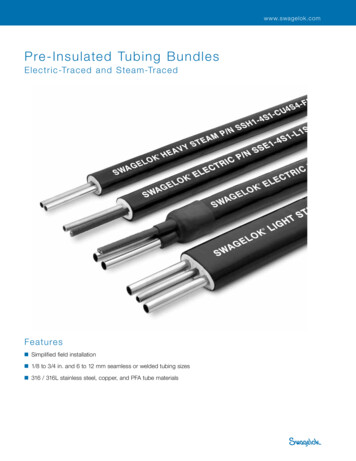
2. INTRODUCTIONnVent provides a total solution for heat tracing instrument and small-diameter process lines.RAYCHEM tubing bundles (RTB) are a pretraced and preinsulated tubing alternative to field tracingand insulating. RTB systems combine RAYCHEM electric or steam heat tracing with tubing andinsulation for a single bundle that can be cut to length in the field.Typical RTB applications include: Impulse lines - to flow transmitters, pressure transmitters, level transmitters, and pressureswitches Sample lines - to analyzers and chromatographs Process lines - for steam supply, condensate return, water purge, chemical feed, and air linesFor European systems, the following nVent literature should be reviewed in order to complete thedesign and installation of RTB Tubing Bundles systems: Installation and Maintenance Manual (DOC-071) Components Selection Guide (DOC-565-R1) Electrical Protection Bulletin (DOC-057) Technical Data Book for Industrial Heat-Tracing Systems (DOC-389-R10)For North American systems, the following nVent literature should be reviewed in order tocomplete the design and installation of RTB Tubing Bundles systems: Installation and Maintenance Guide (H57274) Design Guide for Insulated Pipes and Tubing (H56882)This literature is available from your nVent representative.2.1 PRODUCT LINETubing bundlesRTB tubing bundles are available in a wide range of tubing and heater options (see bundle orderingoptions on page 7).Trace-heating componentsRTB tubing bundles use the full range of XTV and BTV power connection and end seal kits.Bundle accessoriesRTB bundle accessories include heat-shrinkable boots for sealing bundle ends, heat-shrinkablecable entry seals, a jacket patch kit for sealing around thermostat sensor entries, and a hightemperature silicone sealant for sealing bundle ends.nVent.com 5
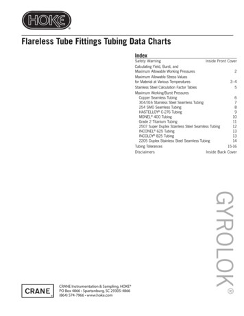
2.2 SYSTEM OVERVIEWAn RTB system consists of pretraced and preinsulated tubing bundles. Each tubing bundle can beconfigured as single- or dual-tube, as shown below, and can be constructed in various sizes andmaterials to meet your small-diameter process piping needs.Rugged outer jacketHeating cableDual-tubeSingle-tubeNonhygroscopicfibrous insulationFigure 1 Tubing bundles, single and dual-tube constructionRAYCHEM tubing bundles (RTB) are pre-engineered to ensure consistent and repeatableperformance for maintenance-free operation. Compared to field fabrication, they simplify designand significantly reduce installation time. Each bundle can be cut to length in the field and ispowered and terminated with simple RTB connection kits. The insulating material consists of anonhygroscopic fibrous glass for maximum heat-loss prevention. Finally, each RTB is encased in ahigh-performance polyurethane outer jacket that provides superior UV resistance and installationcapability to -40 C (-40 F).Contact your nVent representative for design assistance for the following applications: The desired maintain temperature range or process tube size does not appear in Table 1 onpage 8, Table 2 on page 9, or Table 3 on page 10 The ambient temperature range is not between -30 C to 38 C (-20 F to 100 F) Supply voltages of 208 Vac and 277 Vac are used6 nVent.com
2.3 TUBING BUNDLE CATALOG NUMBERRTB comes in a variety of configurations. The following chart outlines the elements that constitutea bundle configuration and the corresponding catalog number. Other configurations are availableon request.RTB* - X - XXX - X - XXX - XXX-X**Electric Traced heating options5B1 5BTV1-CT8B1 8BTV1-CT10B1 10BTV1-CT5B2 5BTV2-CT8B2 8BTV2-CT10B2 10BTV2-CT5X1 5XTV1-CT-T310X1 10XTV1-CT-T315X1 15XTV1-CT-T220X1 20XTV1-CT-T25X2 5XTV2-CT-T310X2 10XTV2-CT-T315X2 15XTV2-CT-T320X2 20XTV2-CT-T2Steam Traced heating optionsLTS Low-temperature steamHTS High-temperature steamPreinsulated OnlyPIO Preinsulate onlyProcess tube wall thickness030 0.030 in10 1.0 mm032 0.032 in15 1.5 mm035 0.035 in049 0.049 in062 0.062 in065 0.065 inProcess tube materialS Seamless 316 SSW Welded 316 SSProcess tubing size1/8 1/8 in1/4 1/4 in3/8 3/8 in1/2 1/2 in3/4 3/4 inM MonelC CopperP PFA6 6 mm8 8 mm10 10 mm12 12 mmNumber of process tubes1 Single-tube2 Dual-tubeExamples:Electric TracedSteam TracedPreinsulated Only* For optional Arctic PVC jacket, add suffix "C" example RTBC** Requires the selection of tubing size XX, tubing material X,and wall thickness XXX for both LTS and 35RTBC-1-1/2-S-049-PIO2.4 BUNDLE MATERIALSBundle jacket Thermoplastic polyether urethane elastomer Halogen-free Abrasion resistant UV-resistant Low-temperature flexibility Optional artic PVCThermal insulation Fibrous glass Water-soluble chlorides less than 100 ppm Non-hygroscopicTubing Welded stainless steel tubing complies with ASTM A-269. Seamless stainless steel tubing complies with ASTM A-269 and A213-EAW. Metric tubing sizes provided with inspection certificate per EN10204.nVent.com 7
3. VERIFY PRODUCT SELECTION3.1 HEATER TYPE AND TEMPERATURE RANGETable 1 shows the minimum and maximum temperatures that can be maintained by the processtube over an ambient temperature range of -30 C to 38 C (-20 F to 100 F). In Table 1, find the column for the desired process tube size. Within the column, find theheater(s) that maintains a minimum temperature at or above the desired maintain temperature. If more than one heating cable will maintain the temperature, choose the one with the lowestmaximum temperature. Make sure that: The T-rating of the heating cable is adequate Only XTV is used if the maximum system exposure temperature is above 85 C (185 F) A thermostat will be used if the maximum temperature in the table is higher than desiredset pointTable 1: Process Tube Maintain Temperatures (Minimum-Maximum) for Ambient Range of -30 C to38 C (-20 F to 100 F ) at 120
2.2 SYSTEM OVERVIEW An RTB system consists of pretraced and preinsulated tubing bundles. Each tubing bundle can be configured as single- or dual-tube, as shown below, and can be constructed in various sizes and materials to meet your small-diameter process piping needs. Figure 1 Tubing bundles, single and dual-tube construction