Transcription
Coiled-Tubing Technology(1995-1998)DEA-67Phase I1PROJECT TO DEVELOP AND EVALUATECOILED-TUBING AND SLIM-HOLE TECHNOLOGYMAURER ENGINEERING INC.2916 West T.C. Jester BoulevardHouston, TX 77018-7098Telephone: (713) 683-8227 Facsimile: (713) 683-6418Internet: http://www.maureng.comE-Mail: mei@maureng.comTR98-10April 1998FThe copyrighted 1998 confidential report is for the use of Participants on the Drilling EngineeringAssociation DEA-67 PHASE II project to Develop and Evaluate Coiled-Tubing and Slim-HoleTechnology and their affiliates, and is not to be disclosed to other parties. Participants and theiraff liatesare free to make copies of this report for their own use.
Coiled-Tubing Technology(1995-1998)TABLE OF CONTENTS.BUCKLING .2CEMENTING . 3COILEDWBING . 4DRILLING . 5FATIGUE .6FISHING . 7LOGGING . 8OVERVIEW .9PIPELINES . 10PRODUCTIONSTRINGS . 11RIGS .12STIMULATION . 13TOOLS . 14WORKOVERS . 15ARTIFICIALLIFT-,Chapter1APPENDIX-Coiled-Tubing References
1. Artificial LiftTABLE OF CONTENTS1. ARTIFICIALLIFTPage. . . . . . . . . . . . . . . . . . . . . . . . . . . . . . . . . . . . . . . . . . . . . . . . . . . . . . . . 1-1.1.1 CENTRALIFT AND SHELL EXPRO (CT-DEPLOYED ESP). . . . . . . . . . . . . . . . . . . . . 1.11.2 HALLIBURTON ENERGY SERVICES (CT ARTIFICIAL LIFT). . . . . . . . . . . . . . . . . . 1-31.3 SCHLUMBERGER DOWELL (UNLOADING WELLS WITH CT)1.4 SHELL WESTERN E&P (CT C 0 2 GAS LIFT). . . . . . . . . . . . . . . . 1-5. . . . . . . . . . . . . . . . . . . . . . . . . . . . . . . . . 1-91.5 TEXACO. McMURRY-MACCO LIFT SYSTEMS. AND DOWELL (CT GAS LIFT)1.6 TRICO INDUSTRIES (JET PUMPS).1-9. . . . . . . . . . . . . . . . . . . . . . . . . . . . . . . . . . . . . . .1.111.7 UNOCAL AND SCHLUMBERGER DOWELL (CT JET PUMP RECOMPLETION) . . 1-131.8 XL TECHNOLOGY (CT DEPLOYED ESPs)F. . . . . . . . . . . . . . . . . . . . . . . . . . . . . . . . .1.161.9 XL TECHNOLOGY (FIELD EXPERIENCE WITH CT ESPs) . . . . . . . . . . . . . . . . . . . . 1-211.10 REFERENCES. . . . . . . . . . . . . . . . . . . . . . . . . . . . . . . . . . . . . . . . . . . . . . . . . . . . . . . . 1-22.OMaurer Engineering Inc
OMaurer Engineering Inc.
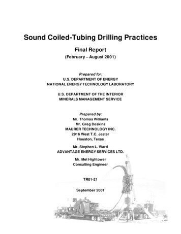
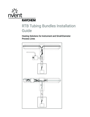
1. Artificial Lift1.1CENTRALIFT AND SHELL EXPRO (CT-DEPLOYED ESP)Centralift and Shell Expro UK (Watkins and Stewart, 1996) described planning and implementinga successful CT-deployed electric submersible pump (ESP) offshore in the Auk field (North Sea). Severalnew tools and procedures were developed for this installation. Various methods were analyzed in thesearch for alternate techniques for deploying ESPs in the field. The first CT-deployed pump was workingwell one year after installation, and a utilization rate of 96% was reported.The conventional method of artificial lift in the Auk field was wireline-retrievable hydraulic jet pumpsinstalled with a rig. Limited capacity in the hydraulic supply system permitted only three wells to be liftedsimultaneously. Shell therefore sought alternate systems for artificial lift.After Shell settled on ESPs, potential deployment methods were investigated. Changing theconventional deployment method would allow a savings of 20% on future workovers, a 50% reduction ininstallation times, and a savings of 100 man-days in bedding. Deployment methods considered were: 1)hydraulic workover rig, 2) cable suspension, and 3) coiled tubing.,-Cable deployment was not suitable due to the well's 74" inclination at depth. CT was determinedto be more economic and better suited to operational experience in the field than a hydraulic workoversystem.New equipment was developed, including high-strength CT connectors to join reels of 2%-in. tubingand to connect completion subassemblies (SSSV etc.). A new packer was designed that could be set andreleased hydraulically. The tubing spool was modified to permit the power cable to exit the wellhead ata right angle (Figure 1-1). This provided amajor cost savings by maintaining the origmal flow-line height.OMaurer Engineering Inc.
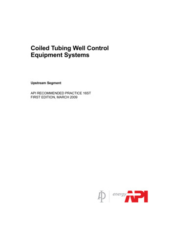
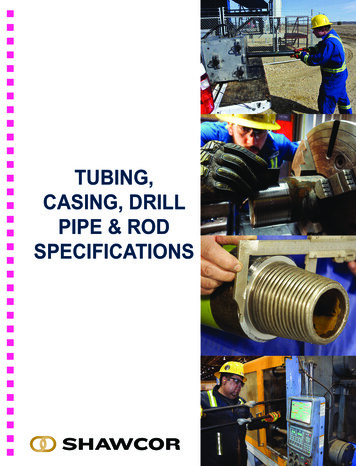
Figure 1-1. Modified Tubing Spool(Stewart et al., 1996)The ESP downhole assembly (Figure 1-2) included a 280-HP motor.OMaurer Engineering Inc.
Sump pr u ra-bhFigure 1-2. ESP Assembly for AukField (Watkins and Stewart, 1996)Platform height restrictions required the fabrication of a special tower frame for supporting thegooseneck and extension. Three stack-up tests were performed with the new equipment, including a fulltrial installation in Aberdeen.1.2HALLIBURTON ENERGY SERVICES (CT ARTIFICIAL LIFT)Halliburton Energy Services (Courville and Clark, 1995) summarized the increased potential of CTfor artificial lift applications, particularly with the advent of larger tubing sizes. CT is clearly well suitedfor use in relatively low-pressure wells in non-hostile environments. ESPs can be deployed on CT, andseveral gas-lift methods are being developed and refined.1-3OMaurer Engineering Inc.
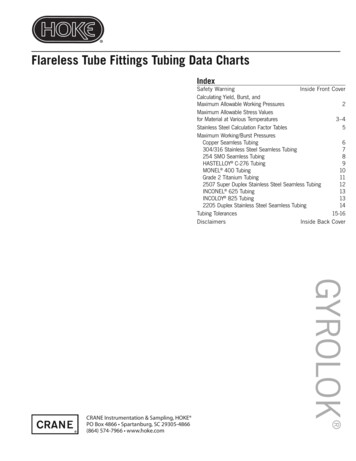
The well-know advantages of CT for production applications include reduced formation damage(underbalanced installation, no pipe dope), improved wellbore integrity (no joints, no leaks), easieroperations (pressure tested at factory, rapid run-in speeds), and lower costs (competitive tubing cost,rigless operations). Disadvantages for production applications include the general undesirability of on-sitewelding, the need to perform hot work outside the well, and the lack of industry experience with large CTwith respect to life and corrosive environments.CT is particularly well suited for deploying ESPs because of the absence of connections. Threadedconnections slow installation and provide a large number of potential cmsh points for the power cable andleak paths for production.ESPs can be deployed on CT with either side-by-side or concentric methods. For the side-by-sidemethod, the power cable is banded to the CT as it is run in the hole (Figure 1-3). f i s method is morepractical and less complex than the concentric method (power cable inside the tubing), except duringinstallation. An advantage of the concentric method is removal of the need to kill the well during theoperation.CT ReelCableWellheadBands that attach and hold electricpower cable to OD of tublng1Connector tor attachmentof tubing to the pump'-\Electric Submenlble Pump (ESP)Figure 1-3. CT-Deployed ESP (Coumille and Clark, 1995)1-4OMaurer Engineering Inc.
Earlier operations deploying ESPs on small CT required only mechanical support from the tubing,that is, the tubing was not used as a flow line. High friction losses inside the CT (Table 1-1) required thatproduction be routed through the annulus. With larger CT, acceptable flow rates are now attainablethrough the CTTABLE 1-1. Maximum Flow Rates for CT (Courville and Clark, 1995)MeasuredMaximum Calculated Flow Rates (BID)DepthTubing Size (in.)-(ft)1.31 Y41#1%22%2'h3%SCHLUMBERGER DOWELL (UNLOADING WELLS WITH CT)Schlumberger Dowell (Gu, 1995) presented an analysis of transient flow for operations involvingnitrogen injection through CT for unloading wells. Transient behavior is very important for determiningoptimum nitrogen volume, injection time, injection depth etc. for unloading a well. They used a CTsimulator to investigate these interactions. Tubing OD, workover fluid, nitrogen rate and nitrogen volumewere analyzed with respect to sensitivity on job design. Job costs can be minimized by optimizinginjection rate and time (i.e., minimize total nitrogen volume).For wells where reservoir pressure is sufficient to lift produced fluids after heavier fluids areremoved from the wellbore, a short-term lifting process can be used to unload the well and restore1-5OMaurer Engineering Inc.
production. The composition of the wellbore fluid changes during the unloading operation; steady-stateconditions are not reached until the well is unloaded and production restored.Schlumberger Dowel1 ran several test cases to investigate the interactions of various parameters onthe success of the unloading operation. One parameter is the composition (i.e., weight) of the fluid in thewellbore. The assumed test conditions included a TD of 12,200 ft, 4-in. casing, no tubing, 4700-psireservoir, and 15,000 ft of 1%-in. CT. Nitrogen is injected at a rate of 300 scfm during run-in. At 12,000ft, injection is increased to 600 scfm for 90 rnin. Flow rates for this operation are charted in Figure 1-4.Figure 1-4. Nitrogen Injection to Unload Well (Gu, 1995)The operation depicted in Figure 1-4 assumes that the wellbore fluid has an SG of 1.O. For theseparameters, the wellbore will be successfully unloaded and begin producing after injection is stopped.However, if the fluid density is assumed to be SG 1.15, not enough fluid will be unloaded to sustainproduction after injection is halted. More injection time would be needed if a heavier fluid is in thewellbore.Another important variable is the impact of reproduced workover fluids. For this analysis, a TD of9030 f?, 2%-in. production tubing to 8500 ft, 4%-in.casing to TD, 3500-psi reservoir, and 15,000 ft of 1%in. CT were assumed. Nitrogen is injected at 300 scfm and the CT is parked at 8800 ft. Unloading canbe completed in 150 rnin if workover fluid was not lost to the formation. If 50 bbl of workover fluid needsto be produced from the formation, injection time must be increased to about 240 min (Figure 1-5).1-6OMaurer Engineering Inc.
Figure 1-5. Unloading with Production of Workover Fluid (Gu, 1995)-An assessment of the volume of workover fluid to be produced back from the formation has to beestimated based on previous experience in the field. Upper and lower bounds should be used to designthe unloading operation.Optimizing injection rate is another important aspect ofjob design. As injection rate is increased,frictional losses in the annulus increase. The drawdown imposed on the formation is a combination ofhydrostatic and fiction pressure at the formation. It is desired to minimize nitrogen volume and injectiontime to minimize job costs.For this analysis, job conditions included a TD of 1 1,050 ft, 27h-in. production tubing to 10,500 ft,4%-in. casing to TD, 2800-psi reservoir, and 13,000 ft of 1 %-in. CT. A constant total volume of 91,500scf was injected. Several nitrogen injection rates were used. At higher rates, friction pressure lowersdrawdown pressure at the formation, and unloading is not successful (Table 1-2).TABLE 1-2. Effect of injection Rate (Gu, 1995)Unloading Results for Different Nitrogen RatesII111(CTOD 1.5 in., N, Volume 91.500 scf)N, RateStop 90111SuccessfulSuccessful nsuccess u unsuccessfu 1-7I1IIIOMaurer Engineering Inc.
CT size also impacts job success. For the case in Table 1-2, an injection rate of 900 scfin would besuccessful if CT diameter were decreased to 1% inches.Depth of injection is anotherimportant parameter. The model wellfor this analysis had a TD of 10,000 ft,2'h-in. tubing to TD, a productivityindex of 0.5 BPDIpsi, and 15,000 ft of1%-in. CT. Liquid return rate for arange of injection rates is shown inFigure 1-6. For 300 scfin, the liquidrate increases only slightly for injectiondepths greater than 4000 ft. Amaximum practical depth can beestimated for any injection rate.Running the CT deeper than this maynot provide any added benefits.Figure 1-6. Return Rate with 1%-in. CT (Gu, 1995)This depth analysis is of course impacted by CT OD (and annulus size). For smaller CT (1 % in.) inlarger tubing (5-in casing), fiction losses are less important. Higher injection rates can increase unloadingrates without creating significant friction losses (Figure 1-7).Y-I. .-.-.--. .-----.#.0.0-------r - -----II.,--.-&lDlk0.lDDDao-----51-(11Figure 1-7. Return Rate with 1%-in. CT (Gu, 1995)1-8OMaurer Engineering Inc.
-.1.4SHELL WESTERN E&P (CT CO, GAS LIFT)Shell Western E&P (Sorrell and Miller, 1997) described the design and evaluation of two CO, gaslift installations in the Denver Unit, a mature field in West Texas. The field is now under tertiary recoverywith CO, water-alternating-gas (WAG) injection. Costs of the CT applications ranged between 65,000and 75,000 (Figure 1-8).Figure 1-8. Costs for CO, CT Gas Lift (Sorrel1 and Miller, 1997)?--More information is presented in Production Strings.1.5TEXACO, McMURRY-MACCO LIFT SYSTEMS, AND DOWELL (CT GAS LIFT)Texaco E&P, McMurry-Macco Lift Systems, and Dowell (Tran et al., 1997) described severalsuccessful installations of CT gas lift. On-location make up of the gas-lift assembly reduced costs. Thecompletion method has been mechanically and economically successful, and will be applied in other fields.The gas-lift mandrels were installed on-site by cutting the CT as the completion is run in (Figure 19). The crew can perform a tensile test for checking connector and string integrity and a pressure test forthe valves and connections.OMaurer Engineering Inc.
Figure 1-9. Work Window for Installing Gas Lift (Tran et al., 1997)In one field installa
hydraulic workover rig, 2) cable suspension, and 3) coiled tubing. ,- Cable deployment was not suitable due to the well's 74" inclination at depth. CT was determined to be more economic and better suited to operational experience in the field than a hydraulic workover system. New equipment was developed, including high-strength CT connectors to join reels of 2%-in. tubing and to connect .