Transcription
How to buildHebel PowerFenceEASYHARD
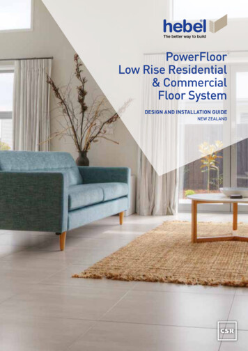
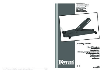
NEW easy PowerFenceThe innovative alternative to brick makesmasonry fencing easy and affordable and an ideal fencing system for DIY.Hebel PowerFence is an attractive andversatile fence system that provides anefficient and effective privacy and noisebarrier for residential applications.Perfect for boundary fencing and lowfront walls, Hebel PowerFence providesa modular masonry structure usinglightweight panels and steel posts whichcan be easily and quickly erected withoutthe need for extensive excavation orstrip footings, as is normally the case fortraditional masonry fence construction.Hebel PowerFence can be finished ineither Expressed or Monolithic and canalso be adapted to include a range ofdifferent decorative treatments such astimber panels or ironwork.The new PowerFence system uses aspecially designed PowerFence Bracket,allowing the single square post to be usedfor a large variety of fence configurations.The PowerFence Bracket can be rotatedaround the post for easy installation ofcorners. The brackets can be separatedvertically on the post to allow panels to be‘stepped’ for sloping terrain.PowerFence:i s simple, cost effective andattractive creates privacy and acts asreflective noise barrier system perfect for boundary fencing andas an alternative to brick or blockmasonry for front fences can be decorated with a rangeof profiles and looks to providedesign flexibility will not rot, is non-combustibleand pest-resistant uses 75mm Hebel PowerPanel,with specially coatedreinforcement to deter corrosionand provide maximum durabilityCan be finished with a choiceof expressed joints or amonolithic look.Expressed foraccentuated panel jointsand simpler final coatingThe top of the fence is capped using a76 x 50mm aluminum U Channel.Panels are easily hand bevelled to give ‘V’jointed horizontal lines between panels.Hebel blocks may be cut and placed on topof each post for further detail.Front and rear of posts are concealed byPowerFence compressed fibre cement postcovers of 15mm thickness.Monolithic for a uniform‘fully rendered’ lookThe top of the fence is capped withHebel blocks.Capping blocks can be cut to size usinga handsaw. Blocks are laid end to endand must be glued together using HebelAdhesive or a suitable constructionadhesive.Front and rear of posts are concealed byPowerFence compressed fibre cement postcovers of 15mm thickness. is designed for the majority ofconditions in urban New Zealandenvironments.2
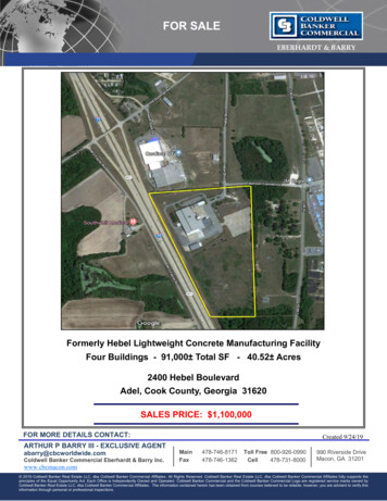
Why use the new Hebel PowerFence?1. New PowerFence can be built with theHebel PowerPanel – for a better pricedfencing systemThe new PowerFence system meets the majorityof environmental conditions for suburban fencing inurban New Zealand using 1800 x 600 x 75mm HebelPowerPanels. Under stricter conditions the 2400 x600 x 75mm PowerPanel can be used. See Table 1.2. New PowerFence uses a single common 75x 75mm square section steel post – again for amore economical Hebel fencing systemThe new PowerFence system requires only onestandard post, for all fence configurations. Thisnew universal post is less expensive than theoriginal system and as it’s universal in design,ordering and delivery is simplified.PowerFence Bracket Lower Arm 133341*Screw 10-24 X 40 Self Drilling 250/Box 141007PowerFence BracketUpper Arm133341*U Channel135152PowerFence Post Cover 240 x 1800 x 15mm 82299PowerFence Post Cover 115 x 1800 x 15mm 82300PowerFence Post 1318833. New PowerFence is now easier to fabricatecorners and easier to install on sloping ground5. New PowerFence is now adjustable duringconstruction in many waysPowerFence uses a new design PowerFenceBracket. The same PowerFence Bracket can beturned upside down to form a starting cleat for thepanels, as well as being a lateral support bracket forall panels. The PowerFence Bracket can be rotatedaround the post, to allow the installer to easily turnthe fence around corners. In addition, the bracketscan be separated vertically on the post to allowpanels to be ‘stepped’ and follow sloping terrain.The PowerFence Bracket is a universalcomponent, which means that if required, itcan be easily repositioned and re-fixed duringconstruction. This is a real advantage for DIY orbuilders installing PowerFence for the first time.4. New PowerFence is now safer toinstall, especially for DIY installers andthe individual builderThe PowerFence Bracket is designed totemporarily secure the panels laterally duringinstallation. This means that as soon as a panel isplaced and the PowerFence Bracket is droppedover the panel, the bracket will safely hold thatpanel in place until the permanent fixings and postcovers are installed.6. Simplified connections using the same screwNew PowerFence uses the same screw fixing forboth attaching the bracket and attaching the finalpost covers. This further simplifies construction.8. New PowerFence is DIY friendlyWe know that many people want to buy and installPowerFence, but the original PowerFence systemwas difficult for DIY installers to manage theinstallation. With the new PowerFence system it’seasily handled by two people working in a homeenvironment with common workshop tools - andthe components are less expensive.Normal Straight PositionNormal Corner PositionUpper Arm7. New PowerFence is faster to installThe universal posts, the adjustable bracketsand the use of lighter 1800 x 600mm panels, allcombine to make the new PowerFence systemmuch faster to install.Lower ArmCleat Straight PositionCleat Corner PositionLower ArmPowerPanel 1800 x 600 x 75mm21987PowerPanel 2400 x 600 x 75mm135097Hebel Capping Block22002Upper ArmThe versatile HebelPowerFence BracketMulti-purpose and adjustable for all-roundeasier and safer construction. Move itup or down while constructing. Rotateit to make a corner. Turn it upside downfor a starting cleat. Use it as a lateralsupport for all the panels. Separate itstwo integrated sections for stepped orterraced fencing. Reposition and refix ifneed be, as you go.Hebel PowerFence Bracket patent pending.Extension Piece 800mm, minimum 300mm insertion 79616* Powerfence brackets are supplied as a set - one upper arm and one lower arm.3
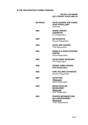
STEP 1STEP 2Determining soil type andrequired post depthRefer to Table 1 below. This table is a generalguide based on broad ground conditions andwind zones. We recommend you consult arelevant designer or local authority to confirmconditions in your area.STEP 3Setting out the fenceInstalling postsMark out the entire fence project on your propertymeasuring the post spacings along this alignment.Dig 300mm diameter post holes ensuring correcthole depth for the required post embedment.See Table 1 for details.The standard PowerFence system is designedfor 1800mm long panels, requiring postspacings of 1885mm, from post centre to postcentre. PowerFence bay lengths can be lessthan 1800mm, and under more strict conditions(see Table 1), increased to an absolutemaximum of 2400mm panel length.Place posts in holes ensuring each post is plumb,holding posts in place with temporary supports.3.1PowerFence Posts are supplied as 2400mmlong for an 1800mm exposed fence height and aminimum 600mm embedment.For other bay sizes, the post set out (centreto centre) is always the panel length in mm,plus 10mm (5mm space at each panel end)plus 75mm. For example - a maximum length2400mm panel post set out would be 2485mmcentre to centre.Note: If embedment requirements exceed 600mmthen simply fix an 800mm length of Power Fence65mm x 65mm x 2.5 SHS post extension, usingscrews or bolts. See Fig.3.4Table 1 - Hebel PowerFence Required Footing EmbedmentMedium Wind SpeedHigh Wind SpeedVery High Wind SpeedRequired Post Section 75x75x2.5 - C35075x75x2.5 - C35075x75x2.5 - C350600 mm900 mm1100 mm75x75x2.5 - C35075x75x2.5 - C35075x75x2.5 - C350600 mm600 mm900 mmPost spacing 2400mmRequired Footing Embedment Note 1Required Post Section Post spacing 1800mmRequired Footing Embedment Note 13.2Slide the extension into the PowerFence Post,and adjust the extension to protrude from thebase of the PowerFence post to ensure thetotal embedment depth required. The extensionmust have a minimum 300mm inserted into thePowerFence Post. Ensure the extension is screwedor fixed on at least two sides of the PowerFencePost. See Fig 3.4Ground Level600mmWind Region as per NZS3604:2011Pour in concrete around the post bases up toground level, allowing concrete to set.1100mmMin 300 Lap3.3Varies (Max 500mm)800mmNote: 1. Pier footing is 300mm dia. Grade 20MPa concrete with steels post embedded to within 50mm - 100mm from the bottom of pier. 2. Table is basedon soil conditions being good ground, As per NZS 3604: 2011 3. If soil condition is encountered other than specified in table, specialist advice is required.3.44
STEP 4Setting PowerPanel levelsPlace a string line along posts at the base level ofthe fence (Fig 4.1).Turn a PowerFence Bracket upside down to formthe cleat position. Put this over the top of post,sliding it down the post so the base of the cleatplate is in line with the string line. Fix off thecleat to the post with screws (Fig 4.2).4.1It’s best to only fix cleats one bay ahead ofthe bay being installed, allowing for minoradjustments as the fence is built (Fig 4.3).STEP 5Installing PowerPanelsbay. This way the PowerFence Bracket is alreadyin the right place for the next bay. These bracketsare then simply lifted by sliding up the postand dropping over the panels as the next bay isinstalled (Fig 5.5 & 5.6).The PowerFence Bracket system is designed as apair, with both brackets identical except one has anupper arm and the other a lower arm to connect tothe post. This is so the brackets can be combinedin a range of configurations - from normal levelground, around corners and sloping ground.5.3NOTE: PowerFence has a maximum heightof 1800mm and normally 3 x 600mm widePowerPanels are stacked horizontally. For anyheight over 1800mm, an engineer must beconsulted for a specific design of both the post andthe supportive base cleat .* When using a PowerPanel with a tongue and grooveedge (teg) notch out the tongue where required so that thePowerfence bracket sits flat on the panel edge.5.4With the starting cleat in place on both posts of afence bay, the first PowerPanel can be installed.4.2Place the PowerPanel on the cleats and haveanother PowerFence Bracket ready in the normallateral-fix position (Fig 5.1).Slide bracket down the post and drop over the topof the first panel to temporarily lock the panel to thepost and stop the panel from falling either side*.There’s no need to permanently fix any lateralbrackets with screws until just before installing thefinal post covers (Fig 5.2).5.15.55.25.6Continue to install panels along the fence usinga trowel bed of Hebel Adhesive between thehorizontal joints of all panels (Fig 5.3 & 5.4) .4.3PowerFence can be built a single bay at a time,but it’s generally easier and faster to install eachrow of panels along the entire fence length at atime. When building PowerFence a bay at a timeit is important to slide both sides of the bracketson to the posts as each panel is stacked in the5
STEP 6Sloping ground andangle cornersCompleting the connections andcovering PowerFence PostsWhen building a fence at a 90 corner simplyfollow Fig 6.1, 6.2 and 6.3.After the fence is assembled and all the panelsglued together, complete all bracket connectionsby screw fixing the bracket arms to posts usingtwo screws for each side.For sloping ground fix the PowerFence Bracketstarting cleat in the correct position to follow thesloping terrain.6.1The vertical step between each bay shouldn’texceed 200mm (approx 15 degree slope).When installing on sloping ground it’s importantto follow a set sequence with each PowerFenceBracket pair ensuring the correct ‘ready’ positionof a bracket for the next bay.6.2When climbing sloping ground, always install thelower arm bracket first, then slide the adjacentupper arm bracket down the post and leaveunfixed. It can then be lifted to fit over the panelin the next ‘higher’ adjacent bay. Conversely,when descending a slope, slide the lower armbracket over the post first and leave loose. Thendrop the upper arm bracket over the panel beinginstalled. This way, the lower arm bracket isalready in position to accept the panel in the nextadjacent ‘lower’ level bay.Angle turns are achieved by embedding twoposts close together at the required turn ofangle and installing the panels at the splayedcorner like an end bay. The two closely alignedposts are then fully covered on both sides usingPowerFence Post Covers and screw fixings.6.3STEP 7Fix the PowerFence Post Covers over thePowerFence Bracket arms and screw fix thepost covers directly to the post using the10-24 x 40mm countersink head screws. Pre-drilland countersink pilot holes into the compressedfibre cement post covers prior to screwinstallation - so the screw heads finish flush withthe post covers7.1Use 150mm vertical screw spacings at allcorners and end posts, and 150mm centres onother intermediate posts.For end bays simply finish with a PowerBracketset on the PowerPanel side of the end post. Thencover all three exposed sides with PowerFencePost Covers, screw fixing the end post cover tothe post at 150mm centres.This completes the structural system for each post.To make installation easier, pilot holes can also bedrilled in the steel posts before fixing screws, usingthe countersunk drilled post covers as a template.On sloping ground it may be necessary to placean additional cut section of post cover to ensurethe stepped panels are completely covered.Post covers are made from thick fibre cement,and therefore can be cut using the samediamond turbo blade on a circular saw as theHebel PowerPanel. The post covers should becut slowly, passing along the cut several timesand increasing the cut depth of the saw by a fewmm on each pass. Always use a guide fencewith the saw to ensure straight neat cuts.Hearing and respiratory protection is also necessaryduring cutting.6
STEP 8STEP 9Decorative panel cappingand post capsThere are a variety of ways to decorativelycomplete PowerFence.8.1Panels can be easily capped and strengthenedusing 76 x 50mm aluminum ‘U Channel’, whichis placed over the top of each panel and glued intoplace with construction adhesive*. Ensure thereis 5mm of expansion space at the ends of eachcapping length, as with the panels (Fig 8.1).To finish the tops of posts, a 600 x 200 x 50mmHebel block can be used. Cut in half to make a300 x 200 x 50mm cap, glue and screw fix overthe post. When fixing post caps into the Hebelpanel use a 100mm, 14-10 bugle head type 17screw. Pre-drill the post cap, glue the post capdown with Hebel Adhesive and screw fix intoplace (Fig 8.2,Fig 8.3, Fig 8.4).Finishing and coatingsPowerFence can be finished using either roll onflexible exterior paints or texture coat finishes.If a supportive aluminum panel capping hasbeen used then no further protection along thetop of the panel is required. However, if thePowerPanel itself is the top edge of the fence,Hebel recommends the top of all panels and100mm either side of the panel from the top, befirst coated with an exterior grade waterproofingcompound such as Mulseal. This should becompatible with the final coating system. It willfurther protect the panel from water ingress,maximizing the life of the coating system used.* when using Powerpanel with a teg edge, the uppertongue edge will need to be removed before filling thechannel.8.2Visit www.hebel.co.nz and view ourHow to build a Hebel PowerFence video.8.38.47
Cutting PowerFenceP owerFence panels are cut using a circularblade power saw fitted with a diamondencrusted, continuous rim, ‘turbo’ sidedmasonry blade and preferably a vacuumdust extraction system. A straight edge cutting fence or squareshould be used to ensure straight crosscuts that are perpendicular to the panellength. Set the blade to cut at a 72mmdepth and then cut all 75mm panelslaid flat horizontally with full supportunderneath. There is no need to cut totallythrough the entire panel thickness – thelast couple of mm thickness will simplyand easily break away. N ote: cutting will expose the internalsteel reinforcement inside the HebelPowerPanel. This exposed steel must bere-coated by simply painting on a layer ofHebel Anti-Corrosion Paint.System componentsPowerPanel for fence panelsThe primary component of the standardPowerFence system is the 1800mm longby 600mm wide and 75mm thick, steelreinforced Hebel PowerPanel.PowerFence BracketThe Hebel PowerFence Bracket acts as thesupportive cleat for base panels and thelateral restraint for all other panels as they arepositioned between posts.PowerFence CappingFor maximum weatherproofing and astronger finish to the top edge, PowerFencepanels can be quickly and simply capped witha purpose made, aluminum 76 x 50mm ‘U’shaped capping channel.PowerFence PostsPowerFence Posts are 75mm x 75mm x2.5mm galvanized box section steel. Theyare supplied in a standard 2.4m length to suitup to a 1.8m high fence when anchored in600mm deep concrete bedded footings.PowerFence Post ExtensionsWhere deeper footings are required apost extension piece is available. Thiseasily connects to the base of a standardPowerFence Post.Note: Extension pieces are only used toincrease the embedment depth of the post inthe ground – the maximum fence height forstandard PowerFence posts is always a max.of 1800mm.PowerFence Post CoversConstruction AdhesiveTo complete the structural design ofPowerFence, sturdy 15mm compressed fibrecement panels are screw fixed onto eachside of the steel posts. These complete thestructure and also decoratively cover thePowerFence Brackets to create an attractive‘engaged pier’ appearance that furtheremulates the look of a solid masonry fence.Selleys Liquid Nails or Fullers Max Bond – forglueing metal fence capping and post coversto metal posts.Hebel Capping Blocks forPowerFence PostsTo cover the tops of posts Hebelmanufactures 50mm thick solid cappingblocks. Simply cut and fix to the top of thefence panels next to the post and create asolid ‘capital’ over the fibre cement covers.Hebel Anti-Corrosion PaintFor protection of any exposed reinforcingsteel when cutting panels.Decorative coatingsHebel PowerFence should be finally coatedwith a flexible exterior acrylic paint orrender system, suitable for use on AAC(autoclaved aerated concrete).Bagged concreteTo cement posts into the ground.Screws1. 10–24 x 40mm: self-drilling metal screw,countersink head. For connecting bracket topost and post cover to post.Tools requiredcordless drill / driver2. 14-10 x 100mm: needle point screw,bugle or hex head. For any fence capping toHebel panel connection. p ower saw fitted with adiamond encrusted continuousrim ‘turbo’ masonry bladeHebel Adhesive r ubber mallet, trowel, oldhandsaw, tin snips20kg Bags – for glueing together of all Hebelcomponents, both panels and blocks.Hebel Patch t ape measure, marker pen,level, string line, clamps10 kg bags. For repair of any holes orconstruction damage to Hebel blocks orpanels - prior to final coating8
Useful construction notes W hen the Hebel PowerFence is in contactwith the ground a suitable waterproofingmembrane such as Mulseal must beused on the panels that will be coveredby, or exposed to, ground soil. Thewaterproofing is applied to both sides,the base and vertical ends of the panel toa minimum height of 100mm above thefinished ground level. P owerFence panels may be cut alongthe panel length to a minimum width of270mm. PowerPanel can be docked inlength to suit the bay width. P aint any steel reinforcement exposed bycutting with Hebel Anti-Corrosion Paint.If the top panel has been cut along thelength, it is best practice to place thatpanel with the cut side facing down. P atch any holes and damage to the panelswith Hebel Patch prior to coating.V ertical movement joints require a knife cutin the base coat render between the panelsurface and the fibre cement cappings priorto application of the final flexible surfacecoating - to allow differential movementbetween panels and posts without crackingthe coating system.Important Safety notes A ll top capping blocks, and / or steelcapping channels, are to be glued andscrewed in place using adhesive and14-10x100mm bugle head type 17 screws.Capping blocks above posts must havesaw cuts either side of each post toallow movement without cracking of thecapping structure. These movement jointsmust be filled with a suitable exteriorsealant and the coating systems mustallow movement without cracking of therender or texture.The use of power tools when cutting concreteor cement based products may cause dustcontaining respirable crystalline silica, and aswith all masonry concrete, this fine dust has thepotential to cause bronchitis, silicosis and lungcancer after repeated and prolonged exposure. F ixing of decorative panels to or acrossposts and any capping blocks should bedone in a way that permits differentialmovement.Hebel products are cement based, whichmay irritate the skin. The wearing of glovesand suitable clothing to reduce the risk ofskin irritation is recommended when handlingHebel products.1. When using hand or power tools on Hebelproducts a P1 or P2 respirator and eyeprotection must be worn.4. Refer to the CSR Hebel MSDS and SafeWork Method Statements for guidelines onsafe handling practices for Hebel products available from www.hebel.co.nz5. H ebel PowerFence is designed as a nonload-bearing fence system to withstandwind and weather conditions as per Table1 in this guide. As such, do not stand oncapping blocks or the fence itself. Donot use panels themselves as a supportor temporary scaffold, and always carrypanels around the site oriented on edge.Avoid laying or storing panels horizontallyunless fully supported underneath.2. Additionally when using power tools forcutting, routing or chasing Hebel products,the use of dust extraction and the wearingof hearing protection is required.3. Hebel panels are despatched in verticallybundled packs, fully strapped for stability.Prior to the cutting of the strapping, thevertical panel bundles should be stabilisedwith temporary restraints such as sashclamps, ratchet straps or Hebel stabilisingbars. This will prevent panels from topplingover and reduces the risk of panel damageor injury. Care should be taken to ensurepanels do not topple when removingindividual panels from bundles.9
1. Can I install PowerFence on sloping oruneven ground?YES. Simply fix the PowerFence Bracketstarting cleat in the correct position tofollow the sloping terrain. The vertical stepbetween each bay shouldn’t exceed 200mm(approximately 15 degree slope). For fullinstructions see Step 6 in the DIY Guide.2. Can I change the direction ofPowerFence to any angle?YES. You can achieve angle turns byembedding two posts close together at therequired turn of angle and installing the panelsat the splayed corner like an end bay. The twoclosely aligned posts are then fully covered onboth sides using PowerFence Post Covers andscrew fixings.3. Can I use PowerFence as aretaining wall?NO. Although the backfilling of light soilsalong the base is permitted, PowerFence isn’tsuitable as a structural soil retaining wall. Thereason is straightforward - PowerFence ismade of autoclaved aerated concrete (AAC)which is too lightweight to be an effective longterm structural barrier against the high massand pressure of deep, wet soils or clay.4. Can I place PowerFence panels directlyonto the ground?YES with waterproofing. The base of thefence should be coated with a suitable exteriorwaterproofing compound, such as Mulseal.This is to protect the panel in the long term, andimportantly, maximise the life of the coatingsyou use to complete the fence.5. Can I install PowerFence higher than1.8m in height?9. How do I determine my soil type andterrain category for post embedment?14. Is it possible to have different postcovers or post decoration?YES with engineering consultancy andadvice. The standard PowerFence systemis engineered to a maximum 1800mm (or6ft) height when using the PowerFencePost and three standard 1800 x 600 x 75mmPowerPanels, slacked horizontally. For all fenceheights above 1800mm you need to consult anengineer for a specific design of both the postand supportive base cleat.The DIY Guide provides general guidanceon broad ground conditions and wind zonesfor PowerFence post embedment. Werecommend you contact your local buildingauthority or consult a relevant designer to findout the conditions for your site.YES. A range of different finishes canbe achieved using Hebel blocks or otherdecorations, to form a natural chipped stone orengaged pier look to the fence posts. However,the structural fibre cement posts covers mustbe installed onto PowerFence before anydecorations can be applied6. Is it possible to install PowerFence atlower heights?YES. PowerPanel can be cut in both lengthand width to suit lower fence heights if needbe. See Cutting PowerFence in the DIY Guidewhich includes safety notes.7. What is the maximum bay length of aPowerFence panel?PowerFence is designed for the majority ofsuburban wind loads with an 1800mm baylength. That’s one reason why the PowerFencesystem uses the standard 1800 x 600 x 75mmHebel PowerPanel.Under more strict design conditions,PowerFence can be installed in up to 2400mmbay lengths using the 2400 x 600 x 75mmPowerPanel. For more details see Table 1 in theDIY Guide.8. Can I cut PowerPanels on site?YES with a minimum 270mm width. See theCutting PowerFence section in the DIY Guidefor details. This includes advice on paintingany steel reinforcement exposed with HebelAnti-Corrosion Paint and important notes onworking safety with Hebel.10. Can I leave my PowerFence unpainted?NO. PowerFence must be rendered or paintedto ensure maximum weatherproofing of thepanels and connections.11. Do I need to fully render myPowerFence?GENERALLY NO. PowerFence does not needa thick, troweled-on render finish unless youwant to achieve a very flat, monolithic surfacefinish similar to fully rendered brickwork.PowerFence is more simply and economicallyfinished by coating with a roll-on colouredacrylic texture coat paint, suitable for use withAAC (autoclaved aerated concrete).12. What is special about thePowerFence Bracket?The PowerFence Bracket is a registereddesign component (patent pending), whichis not only a structural cleat to support thefence panels, but also acts as a lateral supportduring construction to hold the panels in placeimmediately after each panel is placed ontothe fence. This ensures high safety duringinstallation, particularly for DIY installers.15. Do I need to cap PowerFence Posts?YES. The PowerFence Posts are a squarehollow section (SHS) steel and can fill withwater unless capped. A number of options arepossible. The simplest way is to use a 50mmHebel block as a capping piece. Best practice isto use a knock-in plastic or knock-on steel capfor the 75mm x 75mm post, then attach a solidcapping piece for final decoration. You’ll findmore information in the DIY Guide.16. Do I need to cap or treat the top edgesof PowerFence panels?YES. If the PowerPanel is the top edge, Hebelrecommends an initial coat of exterior gradewaterproofing compound - compatible withthe final coating system. It should be appliedon the top and down to 100mm either side.This will protect the panel from water ingressmaximising the life of the coating system used.13. Why do I need Hebel Adhesive betweenPowerFence Panels?Hebel Adhesive between the PowerPanelsbonds them together so they act as acomposite fence bay between posts. Thismaximises the panel strength and ensures thebest substrate for final coating.HELIT115NOV17Frequently Asked QuestionsHebel is a registered trademark of the Xella group. CSR Building Products Limited is an exclusive licensee of Xella. Hebel isdistributed in New Zealand by CSR Hebel, a division of CSR Building Products (NZ) Ltd, a wholly owned subsidiary of CSR in Australia.10
Hebel blocks. Capping blocks can be cut to size using a handsaw. Blocks are laid end to end and must be glued together using Hebel Adhesive or a suitable construction adhesive. Front and rear of posts are concealed by PowerFence compressed fibre cement post covers of 15mm thickness. Can be finished with a choice of expressed joints or a