Transcription
Detached Houses& Low RiseMulti-ResidentialExternal WallsDesign & Installation GuideHEBLA222 Hebel PowerWall DLREW December 2007
The design of the wall systemfor a building requires theservices of professionalconsultants.This design guide has beenprepared as a source ofinformation to providegeneral guidance to theprofessional consultants,and in no way replaces theservices of the professionalconsultants on the project. Noliability can therefore beaccepted by CSR Hebel or other parties for its use.CSR Hebel products andsystems undergo constantresearch and development tointegrate new technology andperformance experience. Asadditional knowledge,technologies and methodsbecome available, CSR Hebel will endeavour tomake these readily availablevia our website:www.hebelaustralia.com.au
Contents1.0Introduction413.0 System Components272.0Benefits514.0 System Installation303.0Typical Applications615.0 Panel Handling344.0How to Design a Hebel PowerWall 716.0 Delivery and Storage355.0Structural Provisions17.0 Construction Details Hebel PowerWall 10136Appendix A:Hebel PowerPanel MaterialProperties54Appendix B:Architectural Specification556.07.08.09.0DurabilityFire Resistance PerformanceEnergy EfficiencySound Transmission & Insulation81315161810.0 Weatherproofing2011.0 Design, Detailing and PerformanceResponsibilities2212.0 Design and Detailing ConsiderationsAppendix C:Designer, Builder, Installer and Inspector/Supervisor Checklist56Appendix D:Testing and Appraisal Certificates2359The system and performance specifications detailed in this guide are guaranteed only for laborator y tested conditions. Actual site conditions should be checkedand advice obtained from an appropriate consultant. Any variations or substitution of materials or assembly requirements, or any compromise in assembly or inquality of the system components may result in failure under critical conditions.It is the responsibility of the architectural designer and engineering par ties to ensure that the details in the CSR Hebel PowerWall Detached Houses & LowRise Multi-Residential External Wall Design & Installation Guide are appropriate for the intended application. The recommendations of this guide are formulatedalong the lines of good building practice, but are not intended to be an exhaustive statement of all relevant data. CSR Hebel accepts no responsibility for, orin connection with, the quality of the recommendations or their suitability for any purpose when installed.CSR Hebel is continuously developing its products. This on-going development may result in changes to product specifications, range and the performancecharacteristics from time to time. The specifications, range and performance characteristics on which the CSR Hebel PowerWall Detached Houses & LowRise Multi-Residential External Walls are based are those current in December, 2007.3CSR Hebel PowerWall Detached Houses & Low Rise Multi-Residential External Walls
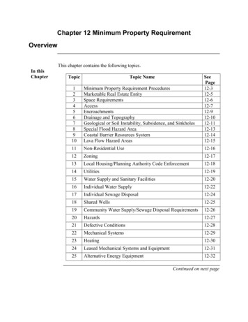
1.0 Introduction1.1 CSR Hebel CSR Hebel is 100% owned byCSR Building Products Limited,one of Australia’s leading buildingproducts companies. CSR Hebel manufactures and markets a rangeof lightweight Autoclaved AeratedConcrete (AAC) blocks, reinforcedPowerPanels , cladding and lintels foruse in the housing and commercialconstruction industry. CSR Hebel also sells complementary mortars, toolsand accessories.In 1989, CSR became involved withHebel and established the Australianoperation. Since then, Hebel haswon wide acceptance as an innovativeand environmentally friendly buildingmaterial due to its speed of construction,excellent thermal/fire/acoustic propertiesand its design versatility.1.2 Design OverviewAs environmental consciousness andsocial responsibility increases, CSR Hebel is striving to exceed theseideals and set new standards in buildingmaterials and residential living.Designed for Inner ComfortWith Hebel PowerWall clients canenjoy a comfortable interior in theirhome, and be comfortable with theirchoice for the environment.Manufacture of Hebel materialsuses a small fraction of the energy andnatural resources used in manufacturingconventional masonry, producing almostno waste or by-products. Hebel’s highly efficient insulation also savespower in heating or cooling the home.sound barrier to external noise andfrom other rooms within the home.Designed for Peace of MindAlthough it’s remarkably lightweight,Hebel is solid and durable. Hebel PowerPanel is reinforced with steelfor extra strength. Hebel is alsoextremely fire-resistant and is not afood source for termites.Designed to SaveAs they’re lightweight, Hebel materials are quick to assemble, savingbuilding time and costs. They alsominimise the need for supportingmaterials, saving budget resources andenergy.1.3 Use Hebel for Better FramedConstructionn Using Hebel PowerPanel foryour framed construction providesyou with cost savings and greaterfloor space for the same buildingdimensions.n Hebel PowerPanel is faster toinstall than bricks, saving on buildingcosts.n Hebel products are lightweight,reducing the structural load on theframe and its design requirementsfor supporting building materials.Fig. 1.1 Panel InstallationDesigned for Inner PeaceHebel PowerWall helps youcreate a tranquil inner space. We haveworked closely with acoustic expertsand testing authorities to engineerinherently superior acoustics from ourwall and floor systems. They create aCSR Hebel PowerWall Detached Houses & Low Rise Multi-Residential External Walls4n Their low weight makes Hebel PowerPanels ideal for use indifficult applications such as slopingsites. An external wall of Hebel PowerPanels is steel-reinforced,solid and secure.n Hebel PowerPanels have betterthermal efficiency than brick veneeror even double brick walls, resultingin reduced heating and coolingcosts. Further thermal efficiency maybe achieved by adding insulation tothe frame cavity.n Hebel is fire-resistant, with a firerating of up to four hours.1.4 Hebel PowerWall Hebel PowerWall for DetachedHouses & Low Rise Multi-ResidentialExternal Walls has been designed forhomes built using either timber orsteel framing and can be used in newdwelling construction, extensions orre-cladding. The system consists of75mm thick, steel-reinforced Hebel PowerPanels , fixed vertically tohorizontal battens attached to theload-bearing frame. For quick, cleanconstruction, Hebel PowerPanels can be ordered in the stock lengths of2400mm, 2700mm and 3000mm andin widths of 300mm and 600mm. The600mm wide PowerPanels are alsoavailable in the additional lengths of1200mm, 2550mm and 2850mm.
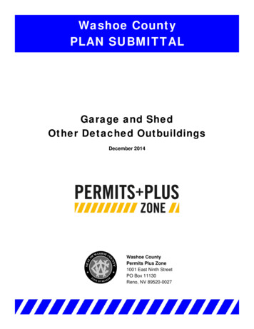
2.0 BenefitsSpeedFig. 2.1 Hebel PowerWall Installed In Ground Floorn With Hebel PowerWall , your home will reach lockup stage sooner.n The installation of Hebel PowerWall is very fast,especially on purpose-designed houses.n Any competent tradesperson can easily install Hebel PowerWall . Two people can install up to 100m2 ofexternal wall in about three days.n The modular design of the dwelling minimises waste.n A standard 2400mm Hebel PowerPanel weighsabout 74kg when delivered*, which two people canposition. No cranes are required.Fig. 2.2 Hebel HomeSpacen Hebel PowerWall gives you great freedom indesigning your home and you can customise the styleby applying coloured and textured coatings to thePowerPanels .n A thinner external wall results in greater internal livingspace and design flexibility. A 50mm reduction inexternal wall thickness can provide about 2% extrainternal space for the same external dimensions.Solidityn Hebel PowerWall is a solid choice. It’s extremelystrong, and each Hebel PowerPanel is steelreinforced.Table 2.1 Comparative Wall Thicknesses (mm)Wall Element WidthWall Systemn Capable of up to four hours fire resistance for a firesource on the PowerPanel side.n Hebel PowerPanel does not provide a food sourcefor vermin or termites.Lower Energy Costsn As with all Hebel products, Hebel PowerPanel hasexcellent thermal properties. This feature results in lowerheating and cooling costs at no additional building expense.StudCavityMasonryLeafTotal WidthBrick Veneer7040110220Hebel PowerWall 7020 - 25*75165 - 170*Brick Veneer9040110240Hebel PowerWall 9020 - 25*75185 - 190** Note: Depending on top hat selection* Calculated at 30% moisture content. At 4% equilibrium moisture content, the PowerPanel would weigh approximately 60kg.Table 2.2 Thermal Properties of Wall SystemsWall SystemsR- ValueCement & metal sheet0.41Weatherboard0.47Concrete block masonry0.53Clay masonry veneer0.55Clay masonry with cavity0.68Hebel PowerWall 1010.91Hebel PowerWall 1063.7400.51.01.52.02.53.03.54.0Note: Sarking or insulation to be added to the above values where applicable to comply with BCA climate zone requirements. R-Values above (excluding Hebel PowerWall solution) are taken from BCA 2007. Refer to Table 8.1 (page 17) for Hebel PowerWall configuration and thermal insulation options.5CSR Hebel PowerWall Detached Houses & Low Rise Multi-Residential External Walls
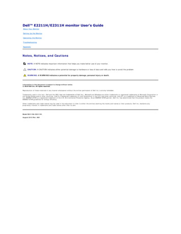
3.0 Typical ApplicationsHebel PowerWall is designed for application in thedomestic, residential markets. Basically, the types of buildingsthat are constructed using Hebel PowerWall aredetached or attached 1 or 2 storey houses, duplexes andtown houses. The Building Code of Australia (BCA) generallyclassifies these buildings as being predominantly of Class 1 orClass 10 building structures.Hebel PowerFloor is a complimentary system that canbe used in conjunction with Hebel PowerWall . Hebel PowerFloor can be quickly installed over timber or steelfloor framing using a construction adhesive & screw fixings.For more information regarding these systems pleasecontact CSR Hebel or visit our websitewww.hebelaustralia.com.auStructurally, Hebel PowerWall uses Hebel PowerPanel as non-loadbearing external cladding. EachPowerPanel is steel reinforced and installed vertically andsecured to steel top hat battens. The top hat battens aresecured to load carrying timber or steel stud frames.Figure 3.1 shows an example of a typical home that usesHebel PowerWall for Detached Houses & Low RiseMulti-Residential External Walls.Fig. 3.1 Typical Home Construction ApplicationCSR Hebel PowerWall Detached Houses & Low Rise Multi-Residential External Walls6
4.0 How to Design a Hebel PowerWall 4.1 Design Process4.2 Compliance With theBuilding Code of Australia (BCA)This section outlines the design process for determining theadequacy of Hebel PowerWall .All building solutions, such as walls, floors, ceilings, etc. mustcomply with the regulations outlined in the BCA or otherauthority.STEP 1: Determine the wind category, stud framinglayout and PowerPanel height requirements.STEP 2: Design Criteria. Where required identify the BCAPerformance Requirements:The BCA is a performance based document, and isavailable in two volumes which align with two groupsof ‘Class of Building’:n Fire Resistance Level (FRL).Volume 1 - Class 2 to Class 9 Buildings; andn Sound insulation performance (Rw values).Volume 2 - Class 1 & Class 10 Buildings - HousingProvisions.n Energy Efficiency (R-Value).STEP 3: The flowchart below can be used to select a type,spacing and quantity of top hats and fixings to suitrequirements.Each volume presents Regulatory PerformanceRequirements for different Building Solutions for variousclasses of buildings and performance provisions.STEP 4: Select insulation and/or sarking material to suitenergy efficiency and condensation requirements.These Performance Provisions include: Structure; FireResistance; Damp & Weatherproofing; Sound Transmission& Insulation; and Energy Efficiency.STEP 5: Check adequacy of sound insulation and fireresistance level.This design guide presents tables, charts and informationnecessary to design a Hebel PowerWall that complieswith the Performance Requirements of the BCA. Thedesigner must check the adequacy of the building solutionfor Performance Requirements outlined by the appropriateauthority.STEP 6: Complete detailed design and documentation.Fig. 4.1 Flow Chart for Design ProcessDETERMINEFrom the building designer,eg. the engineer or local councilWind categoryCONFIRMFrom the frame designerStud capacity and spacingESTABLISHPanel height from designStud capacity and spacingDETERMINE TABLENo. of top hatsMax. stud spacingNo. of screwsCorner effectsControl joint layout 75.1 & 5.45.1, 5.3 & 5.45.2, 5.3 & 5.55.1 - 5.5Section 11.4, Detail 17.9.1CSR Hebel PowerWall Detached Houses & Low Rise Multi-Residential External Walls
5.0 Structural Provisions5.1 OverviewHebel PowerWall basically consistsof Hebel PowerPanel secured tothe framing via horizontal steel tophats. This section provides the basicinformation on the selection of top hatspacings for a given stud spacing andwind category, as well as considerationsto assist the designer in determining theappropriate wall configuration.The design information presented inTable 5.1 to 5.5 has been determinedfor the following top hat types:n Rondo 303 – Rondo BuildingServices Pty Ltd.n Lysaght Topspan 22 – BluescopeSteel Ltd.n FastStud 24TH42.For other brands or types of top hats,contact the manufacturer for designinformation. Minimum performancerequirements for the metal studs, tophats, fixings and Hebel PowerPanel have been provided to assist thedesigner.IMPORTANTThe design and approval of thestructural framing (cold-formed steelor timber) is to be provided by theframing product manufacturer and/orproject engineer.5.2 Principles ofDesignThe principles on which the design isbased include:a) The lateral wind loads applied tothe PowerPanels are transferredinto the horizontal top hats, thento the stud frame, which should bedesigned in accordance with therelevant Australian Standards for theimposed loads. The frame should bedesigned for all bracing and holddown requirements.b) The design of the stud frame shallconsider the weight of suspendedPowerPanels (such as the upperstorey of two-storey construction).c) The system is not considered ascavity construction, as the top hatclearly bridges the cavity, hence thedetails show the necessity of sealingthe windows and door frames, aswell as applying a water resistantexternal coating.d) The system specifications vary withwind load. The notation used inAS1684 Residential Timber FramedConstruction has been adopted.e) The localised effects of windaround corners of buildings havebeen considered in the design andincluded in the tables. The extent ofthis effect is discussed towards theend of this section.Criteria for Corner PanelsDue to the increase of wind load aroundthe corners of buildings, extra top hatsand screws may be necessary (N3 andgreater) for a distance of 1200mm ineach direction from the corner.Tables 5.1 to 5.5 identify the installationcriteria in these areas, in the columnstitled ‘Panel Location - Corner’.Cyclonic Loading EffectsHebel PowerWall for DetachedHouses & Low Rise Multi-ResidentialExternal Walls has been tested atthe James Cook Cyclone StructuralTesting Station (Report No. T5 444) inTownsville. The pullout capacity of thescrew into the back of the Hebel PowerPanel is the critical element inthe design. The results from the cyclictesting showed that the system, inparticular the pullout load of the screw,is unaffected by the cyclic loading. Thedetailing presented in this design guideis satisfactory for cyclonic areas.Earthquake LoadsEarthquake loading has not beenconsidered in this design guide.5.3 Design TablesThis section presents tables to assist thedesigner in the selection of the numberof top hats and number of screws forsecuring the Hebel PowerPanel tothe framing, for a given wind category.IMPORTANTThe wind category is to be used as aguide. The designer should check theproject wind pressure against the valvesgiven in the tables.CSR Hebel PowerWall Detached Houses & Low Rise Multi-Residential External Walls8
Panels Supported at BaseTable 5.1 Number of Top Hats – Panel Supported at Base (such as slab edge or shelf angle)Number of Top Hats Per d Spacing(mm)N20.42N3WindCategoryPanel Length (mm)24002550/27002850/3000Panel LocationPanel LocationPanel 33 (4)33 (4)440.6660033 (4)3444N3, C10.6645033 (4)33 (4)44N4, C20.984503 (4)4 (5)34 (5)45 (6)N5, C31.404504 (5)4 (6)55 (6)55 (7)Note:1 Figures shown in brackets are the top hats required when using RONDO 303 top hats.2 All top hats to be spaced evenly, with top and bottom top hats installed 150mm (typical) from the end of the PowerPanel .3 Additional top hats will be required below all window openings and above openings if a PowerPanel or sill block is to be installed in this location.4 Corner panel location applies to PowerPanels within 1200mm of corners. Permissible wind pressures have been increased by a factor of 2 in thesePowerPanel locations.Table 5.2 Number of Screws Per Panel at Each Top Hat Location - Panel Supported at Base (such as slab edge orshelf angle)Number of Screws Per Panel Per Top re(kPa)Stud 6002323N3, C10.664502223N4, C20.984502323N5, C31.404502334Panel LocationTypicalCornerTop Hat LocationTop Hat LocationNote:1 For fire rated construction a minimum of 3 screws per middle top hat is required (FRL 240/180/180 for a fire source from the PowerPanel side of thewall only).2 Type of screw used is the 14-10x65mm Hex Head Type 17 screw, fixed from inside the building, or 14-10x100mm MP Bugle Head Batten screw, fixedfrom outside the building (as per Table 5.6).3 Corner panel location applies to PowerPanels within 1200mm of corners. Permissible wind pressures have been increased by a factor of 2 in thesePowerPanel locations.Panels Suspended from FrameTable 5.3 Number of Screws Per Panel at Each Top Hat Location - Panel Suspended at Gable EndsMaximumPermissibleSuctionWindPressure(kPa)Stud Spacing(mm)N20.42N30.66WindCategoryNumber of Screws Per PanelPer Top HatMaximum Spacing of Top Hat(mm)Panel LocationPanel 800650N3, C10.6645034800650N4, C20.9845044800450N5, C31.4045044600350Note:1 Top and bottom top hats installed 150mm (typical), and 250mm (max.) from the end of the PowerPanel .2 Top hats to be installed horizontally with PowerPanels to span vertically. Number of Screw Per Panel Per Top Hat Information is not suitable forsoffits or any other areas where the PowerPanel is not vertical.3 Corner panel location applies to PowerPanels within 1200mm of corners. Permissible wind pressures have been increased by a factor of 2 in thesePowerPanel locations.9CSR Hebel PowerWall Detached Houses & Low Rise Multi-Residential External Walls
Table 5.4 Number of Top Hats – Panel Suspended from Framing (such as, second storey construction)Number of Top Hats Per d Spacing(mm)N20.42N3WindCategoryPanel Length (mm)24002550/27002850/3000Panel LocationPanel LocationPanel 4444440.66600444444 (5)N3, C10.66450444444 (5)N4, C20.9845044 (5)44 (6)45 (6)N5, C31.404504 (5)5 (6)56 (7)56 (8)Note:1 Figures shown in brackets are the top hats required when using RONDO 303 top hats.2 All top hats to be spaced evenly, with top and bottom top hats installed 150mm (typical) from the end of the PowerPanel .3 Additional top hats will be required below all window openings and above openings if a PowerPanel or sill block is to be installed in this location.4 Corner panel location applies to PowerPanels within 1200mm of corners. Permissible wind pressures have been increased by a factor of 2 in thesePowerPanel locations.Table 5.5 Number of Screws Per Panel at Each Top Hat Location - Panel Suspended from Framing (such as,second storey construction)Number of Screws Per Panel Per Top HatMaximumPermissibleSuctionWindPressure(kPa)Stud Spacing(mm)N20.42N3WindCategoryPanel LocationTypicalCornerTop Hat LocationTop Hat LocationEndsMiddleEndsMiddle60022230.666002334N3, C10.664502334N4, C20.984502434N5, C31.404502434Note:1 For fire rated construction a minimum of 3 screws per middle top hat is required (FRL 240/180/180 for a fire source from the PowerPanel side of thewall only).2 Type of screw used is the 14-10x65mm Hex Head Type 17 screw, fixed from inside the building, or 14-10x100mm MP Bugle Head Batten screw, fixedfrom outside the building (as per Table 5.6).3 Corner panel location applies to PowerPanels within 1200mm of corners. Permissible wind pressures have been increased by a factor of 2 in thesePowerPanel locations.CSR Hebel PowerWall Detached Houses & Low Rise Multi-Residential External Walls10
5.4 Stud FrameAS3623 and AS/NZS4600 (BCAThe stud frame shall be designed by thesteel stud manufacturer or appropriateproject engineer. Hebel PowerPanel is a masonry product and the supportstructure should be designed to providesufficient stiffness.The steel stud frame shall be designedand constructed in accordance withAS3623 and AS/NZS4600 (BCAPerformance Requirement) withperformance requirements for thestuds of:Properties:Cold-formed steel studs.Minimum yield strength 300MPaMinimum thickness 0.75mm BMT.Coating class Z275 (see Durability).The designer shall specify the needfor noggings.5.5 Steel Top HatOther steel top hats than thosereferenced in this design guide shall bedesigned by the top hat manufactureror appropriate project engineer.The steel top hats shall be designedand constructed in accordance withPerformance Requirement) withperformance requirements for the tophats, of:Concrete’ by Warner, Rangan and Hall(Longman Cheshire). The load carryingcapacity of the Hebel PowerPanel is influenced by several factors, such as:Imposed action (wind).Properties:Lateral stiffness of the supportingstructure (lightweight structural(cold-formed) steel framing).Cold-formed steel top hats.Minimum thickness 0.42mm BMT.Minimum yield strength 300MPa. Stud size and spacings.Coating class Z275 (see Durability). Deflection limit.Alternate steel top hats must have anequivalent or better performance thanthe top hat products outlined inSection 5.1.5.6 Hebel PowerPanel Height of the wall.Number and spacing of the top hats.Number of screw fixings consideredeffective.5.7 FixingsDesign procedures for the verificationof wall systems consisting of Hebel autoclaved aerated concrete (AAC)PowerPanels generally follow thedesign principles outlined in AustralianStandard AS3600 – ConcreteStructures, with the exception ofcover requirements for durability anddevelopment length for reinforcement.Table 5.6 outlines the connection typeand requirements for constructingHebel PowerWall detailed in thisdesign guide. The project engineer orframing manufacturer is responsible forspecification of alternative details. Theminimum performance requirement ofthe screw is:The strength design of the Hebel PowerPanels has been carried outusing the Transformed Section Theory,as detailed in the text book, ‘ReinforcedMinimum screw coating class inaccordance with AS3566: Class 3.(Refer Section 6.0 for Durability).Table 5.6 Screws TypesType of ScrewApplicationTop Hat TypeSocket Type12-11x25mm Hex HeadType 17 screwFix top hat to timber frameRondo 303Lysaght TopSpan 22FastStud 24TH425/16” Hex Mag. Socket10-16x16mm Hex Headself drilling screwFix top hat to steel stud frame(1.2mm BMT max.)Rondo 303Lysaght TopSpan 22FastStud 24TH425/16” Hex Mag. Socket14-10x65mm Hex HeadType 17 screwFix PowerPanel to top hatfrom inside of buildingRondo 303Lysaght TopSpan 22FastStud 24TH423/8” Hex Mag. Socket14-10x100mm MP Bugle HeadType 17 screwFix PowerPanel to top hatfrom outside of buildingRondo 303Lysaght TopSpan 22FastStud 24TH425mm Hex drive bit 50mm long11CSR Hebel PowerWall Detached Houses & Low Rise Multi-Residential External Walls
5.8 DesignConsiderations5.8.1 Structural FramingDesignThe use of Hebel PowerWall intwo-storey construction involves anumber of design issues that requireattention. In conjunction with thefollowing, refer to the ConstructionDetails in Section 17.3 & 17.7.Note, when PowerPanels aresuspended from the stud frame theproject engineer shall design theframe to support the weight of thePowerPanels .Design TipIn order to reduce the load of theupper storey PowerPanels and makeinstallation easier, the lower storeyPowerPanels should be specifiedas 2700mm/3000mm in length andthe upper storey PowerPanels as 2400mm in length. The verticaldimensions can be adjusted to suit.A garage is considered ‘attached’ whenat least one full side of the garage isconnected to the main dwelling.5.8.2 Two StoreyConstructionSteel Frame ConstructionTwo storey construction suits asteel framed dwelling as the weightof the upper storey PowerPanels bear directly on the lower storeyPowerPanels . Note, lower storeyPowerPanels are to bear on theslab. However, consideration should begiven to the sectional size of the lintelsover openings on the lower storey.As the details reveal, only an ‘Ableflex’joint is required at the horizontalPowerPanel junction between theupper and lower PowerPanels .Timber Frame ConstructionIn contrast, the upper storeyPowerPanels cannot rest on thelower storey PowerPanels in timberframed dwellings, due to the effects oftimber shrinkage. Movements in theorder of 25mm can occur in a twostorey timber frame with a timberfirst floor. The fixing method used inHebel PowerWall does not allowfor this extent of differential movementbetween the external skin and thetimber frame.The allowances for shrinkage of timberframing in BCA 2006 Vol. 2, Section3.3.1.10, by providing gaps betweenframing and masonry, should beadopted as a minimum.It is therefore recommended thatthe upper storey PowerPanels beinstalled 35mm clear of the lowerstorey PowerPanels . Duringconstruction a temporary packer isused to separate the PowerPanels and is then removed after thePowerPanels have been screwed tothe top hats.The impact of this constructionis to load the lower storey framewith the weight of the upper storeyPowerPanels . In effect, an extra51kg/m2 (for the weight of the upperPowerPanels ) is being added to theload already carried by the timberframe. The load approximates 1.2kN/m (2.4m PowerPanel ).To simplify the design implications ofthis extra load, it is recommended toadd an extra 1.4m of tributary widthfor a 90kg/m2 Tile Roof load (for 2.4mlong upper PowerPanels ) for thedesign of the lower storey frame andtimber lintels, when using AS1684.The support of the full weight of theupper storey PowerPanels can beadequately supported by the top hatsystem. A full design using a safetyfactor of five has been undertaken andchecked to confirm this. The numberof top hats can be determined inTable 5.4 to support the suspendedPowerPanels , and the PowerPanels screw fixed as per Tables 5.5.5.8.3 Secondary SupportFramingThere is a need for secondary supportframing when:The layout of the main structuralframing does not allow this framingto be used as a support. In this caseCSR Hebel PowerWall Detached Houses & Low Rise Multi-Residential External Walls12a mullion is required to break upthe span of the PowerPanel , orcleats provided to act as supportand connection points for thePowerPanels .Around openings: thePowerPanels adjacent to theopening may not have sufficientcapacity or stiffness to resistthe additional loads that arere-distributed from the opening andinfill PowerPanels .In this case angles are required totransfer the loads from the opening(window) and infill PowerPanels back to the main structural framing.5.8.4 Bracing of theBuildingThe walls of the dwelling shouldbe braced using steel cross bracingwherever possible, to allow the fixingof the PowerPanels from inside thebuilding, such as Teco Speed Bracing.Ply or sheet bracing should be usedon the external wall, if the walls aretoo short for the steel cross bracing(Refer AS 1684-1999). In this case,the full length of the wall should besheeted to prevent misalignment of thePowerPanels .Alternatively, localised strips ofthe sheeting can be fixed to theintermediate studs, between theareas of full sheet bracing, to maintainthe PowerPanel alignment. ThePowerPanels to be installed overthe areas of full plywood sheeting willneed to be fixed from the outside ofthe building using the 100mm longBugle Head Batten screw (Refer Table5.6). The extent of the bracing shouldbe determined by the timber framedesigner or project engineer.NOTECSR Hebel does not recommendfixing Hebel PowerPanels fromthe inside when sheet bracing isinstalled. If sheet bracing is used oversteel or timber frame constructionthen increase the length of the screwfixing the top hat to the stud by thethickness of the sheet bracing (referto Section 5.7).
6.0 Durability6.1 Overview6.3 Coastal AreasDurability means the capability ofa building or its parts to perform afunction over a specified period oftime. It is not an inherent propertyof a material or component. It is theoutcome of complex interactionsamong a number of factors, including:Hebel PowerWall can be used incoastal areas with additional precautionsto ensure salt does not build up on thesurface of the wall. For buildings, whichare 200m to 1000m from a shorelineor large expanse of salt water, suchas, Swan River (west of the NarrowsBridge), Sydney Harbour (east of theHarbour Bridge or Spit Bridge), one ofthe following is required:The service conditions.Material characteristics.Design and detailing.Workmanship.Maintenance.(‘ABCB Guideline Document –Durability in buildings: 2003’)The following sub-sections of thedurability topic are written in orderto provide general guidelines in howbest to provide, enhance and maintainadequate durability of Hebel PowerWall .6.2 Maintenanceand Enhancement ofDurabilityThe durability of Hebel PowerWall can be enhanced by periodic inspectionan
CSR Hebel PowerWall Detached Houses & Low Rise Multi-Residential External Walls 6 3.0 Typical Applications Hebel PowerWall is designed for application in the domestic, residential markets. Basically, the types of buildings that are constructed using Hebel PowerWall are detached or attached 1 or 2 storey houses, duplexes and