Transcription
ISP Network DesignScalable Network Design1
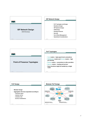
ISP Network Design PoP Topologies and DesignBackbone DesignAddressingRouting ProtocolsSecurityOut of Band ManagementOperational Considerations2
Point of Presence Topologies3
PoP Topologies Core routers – high speed trunk connections Distribution routers and Access routers – highport density Border routers – connections to otherproviders Service routers – hosting and servers Some functions might be handled by a singlerouter4
PoP Design Modular Design Aggregation Services separated according to– connection speed– customer service– contention ratio– security considerations5
Modular PoP DesignOther ISPsISP Services(DNS, Mail, News,FTP, WWW)Web CacheHosted Services &DatacentreBackbone linkto another PoPBackbone linkto another PoPNetworkCoreConsumer cable,xDSL andwireless AccessConsumerDIal AccessLeased line customeraggregation layerMetroE customeraggregation layerNetworkOperationsCentreChannelised circuitsfor leased line circuit deliveryGigE fibre trunksfor MetroE circuit delivery6
Modular Routing Protocol DesignSmaller ISPs Modular IGP implementation– IGP area per PoP– Core routers in backbone area (Area 0/L2)– Aggregation/summarisation where possible into thecore Modular iBGP implementation– BGP route reflector cluster per module– Core routers are the route-reflectors– Remaining routers are clients & peer with routereflectors only7
Modular Routing Protocol DesignLarger ISPs Modular IGP implementation– IGP area per module (but avoid overloading corerouters)– Core routers in backbone area (Area 0/L2)– Aggregation/summarisation where possible into thecore Modular iBGP implementation– BGP route reflector cluster per module– Dedicated route-reflectors adjacent to core routers– Clients peer with route-reflectors only8
Point of Presence Design9
PoP Modules Low Speed customer connections– PSTN/ISDN dialup– Low bandwidth needs– Low revenue, large numbers Leased line customer connections– E1/T1 speed range– Delivery over channelised media– Medium bandwidth needs– Medium revenue, medium numbers10
PoP Modules Broad Band customer connections– xDSL, Cable and Wireless– High bandwidth needs– Low revenue, large numbers MetroE & Highband customer connections– Trunk onto GigE or 10GigE of 10Mbps and higher– Channelised OC3/12 delivery of E3/T3 and higher– High bandwidth needs– High revenue, low numbers11
PoP Modules PoP Core––––Two dedicated routersHigh Speed interconnectBackbone Links ONLYDo not touch them! Border Network––––Dedicated border router to other ISPsThe ISP s front doorTransparent web caching?Two in backbone is minimum guarantee forredundancy12
PoP Modules ISP Services– DNS (cache, secondary)– News (still relevant?)– Mail (POP3, Relay, Anti-virus/anti-spam)– WWW (server, proxy, cache) Hosted Services/DataCentres– Virtual Web, WWW (server, proxy, cache)– Information/Content Services– Electronic Commerce13
PoP Modules Network Operations Centre– Consider primary and backup locations– Network monitoring– Statistics and log gathering– Direct but secure access Out of Band Management Network– The ISP NetworkSafety Belt14
Low Speed Access ModuleWeb CacheAccess NetworkGateway RoutersPrimary RateT1/E1Access ServersPSTN lines tomodem bankTo Core RoutersPSTN lines tobuilt-in modemsTACACS /Radiusproxy, DNS resolver,Content15
Medium Speed Access ModuleAggregation EdgeChannelised T1/E164K and nx64KcircuitsTo Core RoutersMixture of channelisedT1/E1, 56/64K andnx64K circuits16
High Speed Access ModuleAggregation EdgeMetro EthernetChannelised T3/E3To Core RoutersChannelised OC3/OC1217
Broadband Access ModuleWeb CacheDSLAMBRASTelephone NetworkIP, ATMCable RASAccess NetworkGateway RoutersTo Core RoutersThe cable systemSSG, DHCP, TACACS or Radius Servers/Proxies,DNS resolver, Content18
ISP Services ModuleTo core routersService NetworkGateway he19
Hosted Services ModuleTo core routersHosted NetworkGateway RoutersCustomer 1Customer 3Customer 5Customer 7Customer 2Customer 4Customer 620
Border ModuleTo local IXPNB: router has no default route local AS routing table onlyISP1ISP2NetworkBorder RoutersTo core routers21
NOC ModuleCritical ServicesModuleTo core routersOut of BandManagement NetworkCorporate LANHosted NetworkGateway RoutersFirewall2811/32asyncBilling, Databaseand AccountingSystemsNetFlow TACACS SYSLOG Primary DNSAnalyserserverserverNetwork Operations Centre Staff22
Out of Band NetworkOut of BandManagement NetworkRouterconsolesTerminal serverTo the NOCNetFlowenabledroutersNetFlowCollectorOut of Band Ethernet23
Backbone Network Design24
Backbone Design Routed Backbone Switched Backbone– Virtually obsolete Point-to-point circuits– nx64K, T1/E1, T3/E3, OC3, OC12, GigE, OC48,10GigE, OC192, OC768 ATM/Frame Relay service from telco– T3, OC3, OC12, delivery– Easily upgradeable bandwidth (CIR)– Almost vanished in availability now25
Distributed Network Design PoP designstandardised– operational scalability and simplicity ISP essential services distributed aroundbackbone NOC and backup NOC Redundant backbone links26
Distributed Network DesignCustomerconnectionsISP ServicesBackupOperations CentrePOP TwoCustomerconnectionsCustomerconnectionsISP ServicesPOP OnePOP ThreeISP ServicesExternalconnectionsOperations CentreExternalconnections27
Backbone Links ATM/Frame Relay– Virtually disappeared due to overhead, extraequipment, and shared with other customers ofthe telco– MPLS has replaced ATM & FR as the telcofavourite Leased Line/Circuit– Most popular with backbone providers– IP over Optics and Metro Ethernet very commonin many parts of the world28
Long Distance Backbone Links These usually cost more Important to plan for the future– This means at least two years ahead– Stay in budget, stay realistic– Unplanned emergency upgrades will bedisruptive without redundancy in the networkinfrastructure29
Long Distance Backbone Links Allow sufficient capacity on alternative pathsfor failure situations– Sufficient can depend on the business strategy– Sufficient can be as little as 20%– Sufficient is usually over 50% as this offers“business continuity” for customers in the case oflink failure– Some businesses choose 0% Very short sighted, meaning they have no sparecapacity at all!!30
Long Distance LinksPOP TwoLong distance linkPOP OnePOP ThreeAlternative/Backup Path31
Metropolitan Area Backbone Links Tend to be cheaper– Circuit concentration– Choose from multiple suppliers Think big– More redundancy– Less impact of upgrades– Less impact of failures32
Metropolitan Area Backbone LinksPOP TwoMetropolitan LinksPOP OnePOP ThreeMetropolitan LinksTraditional Point to Point Links33
Upstream Connectivity andPeering34
Transits Transit provider is another autonomous system which is usedto provide the local network with access to other networks– Might be local or regional only– But more usually the whole Internet Transit providers need to be chosen wisely:– Only one no redundancy– Too many more difficult to load balance no economy of scale (costs more per Mbps) hard to provide service quality Recommendation: at least two, no more than three
Common Mistakes ISPs sign up with too many transit providers– Lots of small circuits (cost more per Mbps than larger ones)– Transit rates per Mbps reduce with increasing transit bandwidthpurchased– Hard to implement reliable traffic engineering that doesn t needdaily fine tuning depending on customer activities No diversity– Chosen transit providers all reached over same satellite or samesubmarine cable– Chosen transit providers have poor onward transit and peering
Peers A peer is another autonomous system with which the localnetwork has agreed to exchange locally sourced routes andtraffic Private peer– Private link between two providers for the purpose of interconnecting Public peer– Internet Exchange Point, where providers meet and freely decide whothey will interconnect with Recommendation: peer as much as possible!
Common Mistakes Mistaking a transit provider s Exchangebusiness for a no-cost public peering point Not working hard to get as much peering aspossible– Physically near a peering point (IXP) but not present atit– (Transit sometimes is cheaper than peering!!) Ignoring/avoiding competitors because they arecompetition– Even though potentially valuable peering partner togive customers a better experience
Private Interconnection Two service providers agree to interconnect theirnetworks– They exchange prefixes they originate into the routingsystem (usually their aggregated address blocks)– They share the cost of the infrastructure tointerconnect Typically each paying half the cost of the link (be it circuit,satellite, microwave, fibre, ) Connected to their respective peering routers– Peering routers only carry domestic prefixes39
Private InterconnectionUpstreamUpstreamISP2PRPRISP1 PR peering router––––Runs iBGP (internal) and eBGP (with peer)No default routeNo “full BGP table”Domestic prefixes only Peering router used for all private interconnects40
Public Interconnection Service provider participates in an InternetExchange Point– It exchanges prefixes it originates into the routingsystem with the participants of the IXP– It chooses who to peer with at the IXP Bi-lateral peering (like private interconnect) Multi-lateral peering (via IXP’s route server)– It provides the router at the IXP and provides theconnectivity from their PoP to the IXP– The IXP router carries only domestic prefixes41
Public 4-PRISP3-PRISP1ISP2-PR ISP1-PR peering router of our ISP––––Runs iBGP (internal) and eBGP (with IXP peers)No default routeNo “full BGP table”Domestic prefixes only Physically located at the IXP42
Public Interconnection The ISP’s router IXP peering router needs carefulconfiguration:––––It is remote from the domestic backboneShould not originate any domestic prefixes(As well as no default route, no full BGP table)Filtering of BGP announcements from IXP peers (in and out) Provision of a second link to the IXP:– (for redundancy or extra capacity)– Usually means installing a second router Connected to a second switch (if the IXP has two more more switches) Interconnected with the original router (and part of iBGP mesh)43
Public P4-PRISP3-PRISP1-PR1ISP1ISP2-PR Provision of a second link to the IXP means consideringredundancy in the SP’s backbone– Two routers– Two independent links– Separate switches (if IXP has two or more switches)44
Upstream/Transit Connection Two scenarios:– Transit provider is in the locality Which means bandwidth is cheap, plentiful, easy toprovision, and easily upgraded– Transit provider is a long distance away Over undersea cable, satellite, long-haul cross countryfibre, etc Each scenario has different considerationswhich need to be accounted for45
Local Transit ProviderISP1ARBRTransit BR ISP’s Border Router––––Runs iBGP (internal) and eBGP (with transit)Either receives default route or the full BGP table from upstreamBGP policies are implemented here (depending on connectivity)Packet filtering is implemented here (as required)46
Distant Transit ProviderAR1BRTransitISP1AR2 BR ISP’s Border Router–––––Co-located in a co-lo centre (typical) or in the upstream provider’s premisesRuns iBGP with rest of ISP1 backboneRuns eBGP with transit provider router(s)Implements BGP policies, packet filtering, etcDoes not originate any domestic prefixes47
Distant Transit Provider Positioning a router close to the Transit Provider’sinfrastructure is strongly encouraged:– Long haul circuits are expensive, so the router allowsthe ISP to implement appropriate filtering first– Moves the buffering problem away from the Transitprovider– Remote co-lo allows the ISP to choose another transitprovider and migrate connections with minimumdowntime48
Distant Transit Provider Other points to consider:– Does require remote hands support– (Remote hands would plug or unplug cables,power cycle equipment, replace equipment, etc asinstructed)– Appropriate support contract from equipmentvendor(s)– Sensible to consider two routers and two longhaul links for redundancy49
Distant Transit ProviderAR1BR1TransitAR2ISP1BR2 Upgrade scenario:– Provision two routers– Two independent circuits– Consider second transit provider and/or turning up at an IXP50
Summary Design considerations for:– Private interconnects Simple private peering– Public interconnects Router co-lo at an IXP– Local transit provider Simple upstream interconnect– Long distance transit provider Router remote co-lo at datacentre or Transit premises51
AddressingAddressing Resources and Protocols52
Getting IP address space Take part of upstream ISP s PA spaceor Become a member of your Regional Internet Registry andget your own allocation– Require a plan for a year ahead– General policies are outlined in RFC2050, more specific details areon the individual RIR website There is no more IPv4 address space at IANA– Most RIRs are now entering their final /8 IPv4 delegationpolicies– Limited IPv4 available– IPv6 allocations are simple to get in most RIR regions53
What about RFC1918 addressing? RFC1918 defines IP addresses reserved for private Internets– Not to be used on Internet backbones– http://www.ietf.org/rfc/rfc1918.txt Commonly used within end-user networks– NAT used to translate from private internal to public externaladdressing– Allows the end-user network to migrate ISPs without a majorinternal renumbering exercise Most ISPs filter RFC1918 addressing at their network edge– http://www.cymru.com/Documents/bogon-list.html54
What about RFC1918 addressing? List of well kn
ISP Network Design PoP Topologies and Design Backbone Design Addressing Routing Protocols Security Out of Band Management Operational Considerations 2. Point of Presence Topologies 3. PoP Topologies Core routers –high speed trunk connections Distribution routers and Access routers –high port density Border routers –connections to other providers Service .
