Transcription
ISP Network DesignISP WorkshopsThese materials are licensed under the Creative Commons Attribution-NonCommercial 4.0 International 4.0/)Last updated 9 th October 20181
AcknowledgementspThis material originated from the Cisco ISP/IXP WorkshopProgramme developed by Philip Smith & Barry GreenenI’d like to acknowledge the input from many network operators in theongoing development of these slides, especially Mark Tinka of SEACOM forhis contributionspUse of these materials is encouraged as long as the source is fullyacknowledged and this notice remains in placepBug fixes and improvements are welcomednPlease email workshop (at) bgp4all.comPhilip Smith2
ISP Network DesignPoP Topologies and Designp Backbone Designp Addressingp Routing Protocolsp Infrastructure & Routing Securityp Out of Band Managementp Test Networkp Operational Considerationsp3
Point of Presence Topology &Design4
PoP ComponentspCore routersnpDistribution routersnpConnections to other providersServices routersnpHigh port density connecting end-usersBorder routersnpFor large networks, aggregating access to coreAccess routersnpHigh speed trunk connectionsHosting and serversSome functions might be handled by a single router5
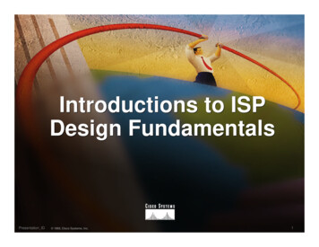
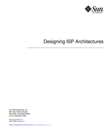
PoP DesignpModular Design is essentialnpQuite often modules map on to business units in a networkoperatorAggregation Services separated according tonnnnnnConnection speedCustomer service/expectationsLatencyContention ratioTechnologySecurity considerations6
Modular PoP DesignOther Operators &Internet Exchange PointborderNetworkOperationsCentreborderBackbone linkto another PoPBackbone linkto another PoPNOCcorecoreWebhosting / ISPCloud ServicesCDN Hosted CachesCorporate customeraggregation layerEthernetFibre trunksISP ServicesMobile CoreConsumeraggregation layerEthernetFibre trunks(DNS, SMTP, POP3Portal, WWW)7
Modular Routing Protocol DesignpIGP implementationnIS-IS is more common in larger operatorspnOSPFv2 & OSPFv3 also usedppEntire backbone operates as ISIS Level 2Backbone is in Area 0, each PoP in its own non-zero AreaModular iBGP implementationnnnBGP route reflector clusterCore routers are the route-reflectorsRemaining routers are clients & peer with route-reflectors only8
Point of Presence Design Details9
PoP CoreTwo dedicated high performance routersp TechnologypnnnpHigh Speed interconnect (10Gbps, 100Gbps, 400Gbps)Backbone Links ONLY; no access servicesDo not touch them!Service Profilen24x7, high availability, duplicate/redundant design10
PoP Core – detailspRouter specificationnnHigh performance control plane CPUDoes not need a large number of interface/line cardsppOnly connecting backbone links and links to the various servicesHigh speed interfacesnnAim as high as possible10Gbps is the typical standard initial installation nowpnPrice differential between 1Gbps and 10Gbps justifies the latter whenlooking at cost per GbpsMany operators using aggregated 10Gbps links, also 100Gbps11
Border NetworkDedicated border routers to connect to other NetworkOperatorsp TechnologypnnnnHigh speed connection to coreSignificant BGP demands, routing policyDDoS front-line mitigationDifferentiation in use:pppConnections to Upstream Providers (Transit links)Connections to Private Peers and Internet Exchange PointService Profilen24x7, high availability, duplicate/redundant design12
Border Network – detailspRouter specificationnnHigh performance control plane CPUOnly needs a few interfacespnpOnly connecting to external operators and to the network core routersTypically a 1RU or 2RU deviceHigh speed interfacesnnnn10Gbps standard to the core10Gbps to Internet Exchange PointEthernet towards peers (1Gbps upwards)Ethernet towards transit providers (1Gbps upwards)13
Border Network – detailspRouter options:nRouter dedicated to private peering and IXP connectionspOnly exchange routes originated by respective peers§ No default, no full Internet routespnControl plane CPU needed for BGP routing table, applying policy, andassisting with DDoS mitigationRouter dedicated to transit connectivitypMust be separate device from private peering/IXP router§ Usually carries full BGP table and/or default routeppControl plane CPU needed for BGP routing table, applying policy, andassisting with DDoS mitigationNote: the ratio of peering traffic to transit traffic volumeis around 3:1 today14
Corporate Customer AggregationpBusiness customer connectionsnpTechnologynnnpHigh value, high expectationsFibre to the premises (FTTx or GPON)Aggregated within the PoP moduleUsually managed service; customer premise router provided bythe operatorService ProfilennTypically demand peak performance during office hoursOut of hours backups to the “Cloud”15
Corporate Customer Aggregation – detailspRouter specificationnnpMid-performance control plane CPUHigh interface densitiesInterface types:nn10Gbps uplink to coreMultiple 10Gbps trunksppCustomer connections delivered per VLANProvided by intermediate ethernet switch or optical equipmentDirect Fibre Trunk Linkscorecore16
Corporate Customer Aggregation – detailspRouter options:nSeveral smaller devices, aggregating multiple 1Gbps trunks to10Gbps uplinkspTypically 1RU routers with 16 physical interfaces§ 12 interfaces used for customer connections, 4 interfaces for uplinkspMay need intermediate Distribution Layer (usually ethernet switch) toaggregate to core routersDirect Fibre Trunk LinksndistributioncorecoreOne larger device, multiple aggregation interfaces, with multiple10Gbps or single 100Gbps uplink to corepTypical 8RU or larger with 100 physical interfaces17
Consumer AggregationpHome users and small business customer connectionsnpTechnology:nnnnpLow value, high expectationsFibre to the premises (FTTx or GPON)Still find Cable, ADSL and 802.11 wireless usedAggregated within the PoP moduleUnmanaged service; with customer premise router provided bythe customerService ProfilenTypically demand peak performance during evenings18
Consumer Aggregation – detailspRouter specificationnnpMid-performance control plane CPUHigh interface densitiesInterface types:nn10Gbps uplink to coreMultiple 10Gbps trunksppCustomer connections delivered per VLANProvided by intermediate ethernet switch or optical equipmentDirect Fibre Trunk Linkscorecore19
CDN Hosted Services and CachesContent provider supplied infrastructurep Technology:pnEach CDN provides its own equipmentpnRequires direct and high bandwidth connection to the CoreNetworkpppUsually a number of servers & ethernet switch, possibly a routerUsed for cache fillUsed to serve end-usersService ProfilenHigh demand high availability 24x720
CDN Hosted Services and Caches – detailspEvery CDN is different, but follow a similar patternnOption 1:corenConnection to NetworkOperator Core RouterOption 2:borderCDN BRcoreConnection to Network OperatorBorder Router (Transit/Cache-Fill)And Core Router (End-User Access)21
Mobile CoreConnection to Cellular Network infrastructurep Technology:pnnpDedicated & redundant routersDirect connection to Network Operator CoreService ProfilenHigh demand high availability 24x722
Mobile Core – detailspCellular network connectivitynCellular infrastructure border routers (Cell GW) need to be:pppHigh performanceHigh throughputAble to do packet filtering as requiredRadio NetworkEPGCell GWcoreCell GWcoreCellular IPInfrastructure23
Network Operator ServicesInfrastructure / Customer servicesp Technology:pnnpRedundant server cluster behind two routers, hosting virtualmachinesOne virtual machine per serviceServicesnnnnDNS (2x cache, 2x authoritative)Mail (SMTPS Relay for Customers, POP3S/IMAPS for Customers,SMTP for incoming e-mail)WWW (Operator Website)Portal (Customer Self-Service Portal)24
Network Operator Services – detailspInfrastructure is usually multiple 1RU or 2RU serversconfigured into a clusternnHosting Virtual Machines, one VM per ServiceExamples:pppppppWWWCustomer PortalAuthoritative DNSDNS Cache (Resolver)SMTP Host (incoming email)SMTPS Relay (outgoing email from customers)POP3S/IMAPS (Secure Mail Host for customers),servicescoreservicescoreServer ClusterHostingServices VMs25
Webhosting/Cloud ModulepHosted Services & DataCentrenpTechnologynnp“Cloud Computing” – or: someone else’s computer!Redundant server cluster behind two routers, hosting virtualmachinesOne virtual machine per serviceServicesnnnContent hosting / Websites (one VM per customer)Compute Services (one VM per customer)Backups (one VM per customer)26
Cloud Module – detailspInfrastructure is usually multiple 1RU or 2RU serversconfigured into a clusternnHosting Virtual Machines, one VM per ServiceSeveral clusterspnEach customer gets one VMpppLimit the number of customersper clusterEach VM in a separate private VLANAvoid exposing one customer VMto any other customerDCcoreDCcoreServer ClusterHosting CustomerVMsCommercial and Open Source solutions available27
Network Operations CentreManagement of the network infrastructurep Technology:pnpGateway router, providing direct and secure access to thenetwork operator core backbone infrastructureServices:nnnnnNetwork monitoringTraffic flow monitoring and managementStatistics and log gatheringRTBH management for DDoS mitigationOut of Band Management NetworkpThe Network “Safety Belt”28
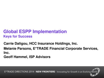
NOC ModulepTypical infrastructure layout:To core routersCritical ServicesModuleCorporate LANFirewallnocCluster includingVMs for:Flow AnalyserAuth ServerLog CollectorPrimary DNSBilling, Databaseand AccountingSystemsConsolesOOB EthernetOut of BandManagement NetworkNetwork Operations Centre Staff29
SummarypNetwork Operator PoP core:nnnnnModularityHigh speed, no maintenance coreDirect Ethernet cross-connectsTwo of everythingRely on performance of IS-IS (or OSPF) and technologies suchas BFD (Bi-directional Forwarding Detection) for rapid re-routingin case of device failure30
Network Operator BackboneInfrastructure Design31
PrioritiespToday’s Internet is very different from 1990snpToday:nnpBack then, online content was via FTP sites, Gopher, bulletinboards, and early single location websitesDominance of contentDominance of content distribution infrastructure & networksEnd user focus on social media, cloud services, and online videos/photosnni.e. Google/YouTube & Facebook accounts for 75% of traffic foran access providerAccess provider is merely a path between the CDN and the enduser32
PrioritiespPriority for a service provider:npProviding lossless connectivity at high speed & high availabilitybetween content provider and end-userHow:nnnnnLow latency backbone infrastructureHigh bandwidth backbone infrastructureContent Cache & Distribution Network HostingInterconnection with other local operators (private and IXP)Optimised transit to content distribution hubs (for Cache fill)33
Content delivery is competitive!pCompetition in local marketplace is all about speed andquality of content deliveryne.g.34
These are NOT PrioritiesLast century’s hierarchical transit / incumbent telcomodelp Anti-competitive barriers between operators serving thesame marketp Legislative barriers preventing interconnectionp35
Backbone DesignpRouted BackbonenpPoint-to-point links using Fibre OpticsnnpSome operators use MPLS for VPN service provisionEthernet (1GE, 10GE, 40GE, 100GE, )Packet over SONET (OC48, OC192, OC768)All other infrastructure technologies from the 90s and00s are now obsoletenATM, Frame Relay, PDH, X.25, FDDI, 36
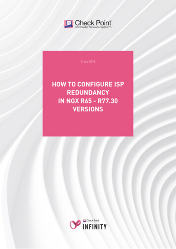
Distributed Network DesignpImportant to standardise the PoP designnnnnnNothing should be custom builtSettle on two or three standard designs (small/medium/large)Using much the same hardware, same layoutAnd deploy across backbone as requiredMaximises sparing, minimises operational complexityISP essential services distributed around backbonep NOC and backup NOCp Redundant backbone linksp37
Distributed Network DesignCustomerconnectionsISP ServicesBackupOperations CentrePOP TwoCustomerconnectionsCustomerconnectionsISP ServicesPOP OnePOP ThreeISP ServicesExternalconnectionsOperations CentreExternalconnections38
Backbone LinkspFibre OpticsnnMost popular with most backbone operators todayDark FibreppnLeased “lambdas”pnAllows the operator to use the fibre pair as they please (implementingeither CWDM or DWDM to increase the number of available channels)Leased from fibre owner or purchased outrightOperator leases a wavelength from the fibre provider for datatransmissionOn the routers:ppIP on Ethernet is used more and more for long haulIP on SONET/SDH is more traditional long term39
Fibre Optics – Brief SummarypDWDM – Dense Wave Division MultiplexingnnnnnpITU-T G.694.1Allows up to 96 wavelengths per fibre optic pair (transmit and receive)λ: 1528 nm-1563 nm0.4 nm between channelsCostly, due to equipment and transceiversCWDM – Coarse Wave Division MultiplexingnnnnnITU-T G.694.2λ: 1271 nm-1611 nmAllows up to 18 wavelengths per fibre optic pair (transmit and receive)20 nm between channelsUses G.652.C and G.652.D specification fibre optic cables40
Long Distance Backbone LinkspThese usually cost more if no access to Dark FibrennpLeasing lambdasLeasing SONET/SDH circuitImportant to plan for the futurennnThis means at least two years aheadStay in budget, stay realisticUnplanned “emergency” upgrades will be disruptive withoutredundancy in the network infrastructure41
Long Distance Backbone LinksAllow sufficient capacity on alternative paths for failuresituationsp What does sufficient mean?pnFor top quality operators, this is usually at least 50% sparecapacityppnLower cost operators offer 25% spare capacitypnOffers “business continuity” for customers in the case of any link failureAllows for unexpected traffic bursts (popular events, releases etc)Leads to congestion during link failures, but still usable networkSome businesses choose 0%pVery short sighted, meaning they have no spare capacity at all!!42
Long Distance LinksPoP TwoPoP ThreeLong distance link, primarypath from PoP One to PoP TwoPoP One43
Long Distance LinksPoP TwoPoP One to PoPTwo link breaksPoP OnePoP ThreeAlternative/Backup PathSufficient capacity to carry trafficbetween PoP One and PoP Two44
Metropolitan Area Backbone LinkspTend to be cheapernnnpCircuit concentrationChoose from multiple suppliersExisting ducts allow easy installation of new fibreThink bignnnMore redundancyLess impact of upgradesLess impact of failures45
Metro Area Backbone LinksPoP TwoMetro Fibre LinksPoP OnePoP ThreeMetro Fibre Links46
Addressing47
TodaypNew networks are deployed using dual stacknnThe infrastructure supports both IPv6 and the legacy IPv4addressingThe infrastructure runs IPv6 and IPv4 side by sideppIPv4 address space is almost no longer availablenpNo interaction between IPv4 and IPv6 – independent protocolsMany backbones using private IPv4 address space (RFC1918 orRFC6598) and using NAT to translate to public address spaceIPv6 address space is plentifulnIPv6 is supported on almost every networking device availabletoday48
IPv4 & IPv6 dual stack operationppppIPv6 is designed to work independently of IPv4If a destination is available only over IPv4, IPv4 will be usedIf a destination is available over IPv4 & IPv6, HappyEyeballs (RFC8305) ensures that the client uses thetransport for the best user experienceBrief summary of Happy Eyeballs for a dual stack device:nnApplication asks for IPv4 and IPv6 addressesIf both types are returned within 50ms of each other, application opensconnection using IPv6 addresses first, followed by IPv4 addressespnEach attempt comes after at least 100ms delay or delay dependent onobserved RTTApplication uses the transport which responds with a connection first49
Where to get IP addresses and AS numbersppYour upstream ISPAfricanpAsia and the PacificnpARIN – http://www.arin.netLatin America and the CaribbeannpAPNIC – http://www.apnic.netNorth AmericanpAfriNIC – http://www.afrinic.netLACNIC – http://www.lacnic.netEurope and Middle EastnRIPE NCC – http://www.ripe.net/info/ncc50
Internet Registry Regions51
Getting IP address space (1)pFrom your Regional Internet RegistrynBecome a member of your Regional Internet Registry and getyour own allocationpnFor IPv6:pnMembership open to all organisations who are operating a networkMinimum allocation is a /32 (or larger if you will have more than 65k /48assignments)For IPv4:pppAPNIC & RIPE NCC have up to /22 for new members only (to aid with IPv6deployment)ARIN has nothingAfriNIC and LACNIC have very limited availability – check their websites52
Getting IP address space (2)From your upstream ISPp For IPv4:pnVery unlikely they will give you more than a single IPv4 addressto NAT on toppThis simply does not scale (NAT limitations)For IPv6:nnReceive a /48 from upstream ISP’s IPv6 address blockReceive more than one /48 if you have more than 65k subnets53
Getting IP address space (3)If you need to multihomep For IPv4:pnnpNothing available from upstream providerAddress block from RIR (see earlier)For IPv6:nApply for a /48 assignment from your RIRpMultihoming with the provider’s /48 will be operationally challenging§ Provider policies, filters, etc54
What about RFC1918 addressing?pRFC1918 defines IPv4 addresses reserved for privateInternetsnnpCommonly used within end-user networksnnpNot to be used on Internet backboneshttp://www.ietf.org/rfc/rfc1918.txtNAT used to translate from private internal to public external addressingAllows the end-user network to migrate ISPs without a major internalrenumbering exerciseISPs must filter RFC1918 addressing at their network l55
What about RFC6598 addressing?pRFC6598 defines shared IPv4 address spacennpCommonly used within service provider backbonesnnpUsed for operators using Carrier Grade NAT deviceshttp://www.ietf.org/rfc/rfc65988.txtNAT used to translate from shared internal to public external addressingAllows the network operator to deploy an IPv4 infrastructure without thefear of address space used between them and their CPE conflicting withRFC1918 address space used by their customersNetwork Operators must filter RFC6598 addressing at theirnetwork l56
What about RFC1918 & RFC6598 addressing?pThere is a long list of well known xtIncluding:nnnnnnnnnFalse belief it conserves address spaceAdverse effects on TracerouteEffects on Path MTU DiscoveryUnexpected interactions with some NAT implementationsInteractions with edge anti-spoofing techniquesPeering using loopbacksAdverse DNS InteractionSerious Operational and Troubleshooting issuesSecurity IssuespFalse sense of security, defeating existing security techniques57
Private versus Globally Routable IPv4 AddressingpInfrastructure Security: not improved by using private addressingnpTroubleshooting: made an order of magnitude hardernnpStill can be attacked from inside, or from customers, or by reflectiontechniques from the outsideNo Internet view from routersOther Network Operators cannot distinguish between down and brokenSummary:nALWAYS use globally routable IP addressing for ISP Infrastructure58
Why not NAT? (1)pHow to scale NAT performance for large networks?npLimiting tcp/udp ports per user harms user experienceCGN deployment usually requires redesign of SP networknDeploy in core, or access edge, or border, ?Breaks the end-to-end model of IPp Breaks end-to-end network securityp Breaks non-NAT friendly applicationspnOr NAT has to be upgraded (if possible)59
Why not NAT? (2)pLimited ports for NAT:nnnnnpTypical user deviceTCP/UDP ports per IPv4 addressImplies 130000/400 usersOne IPv4 /22 has:One IPv4 /22 could support:400 sessions130k320 users1024 addresses320k usersSizing a NAT device has to be considered quite seriously60
Why not NAT? (3)pMakes fast rerouting and multih
ISP Network Design pPoPTopologies and Design pBackbone Design pAddressing pRouting Protocols pInfrastructure & Routing Security pOut of Band Management pTest Network pOperational Considerations 3. Point of Presence Topology & Design 4. PoPComponents pCorerouters nHigh speed trunk connections