Transcription
Delta ControlsWiring and Installation Guidelines
Copyright InformationDocument Title:Delta Controls Wiring and Installation GuidelinesEdition:1.5Revised:June 2012No part of this document may be reproduced, transmitted, transcribed,stored in a retrieval system or translated into any language (natural orcomputer), in any form or by any means, without the prior writtenpermission of Delta Controls Inc.Limited permission is granted to reproduce documents released inAdobe Portable Document Format (PDF) electronic format in paperformat. Documents released in PDF electronic format may be printedby end users for their own use using a printer such as an inkjet orlaser device. Authorized distributors of Delta Controls Inc. products(Delta Partners) may print PDF documents for their own internal use orfor use by their customers. Authorized Delta Partners may producecopies of released PDF documents with the prior written permission ofDelta Controls Inc.Information in this document is subject to change without notice anddoes not represent a commitment to past versions of this document onthe part of Delta Controls Inc.Delta Controls Inc. may make improvements and/or changes to thismanual/the associated software/or associated hardware at any time.BACstat is a registered trademark of Delta Controls Inc. enteliSYS,enteliBUS and enteliTOUCH are trademarks of Delta Controls Inc.Copyright Delta Controls Inc. All rights reserved. Printed in CanadaDelta Controls: telephone: 604.574.9444, www.deltacontrols.com
Wiring and Installation Guidelines, Edition 1.5Table of ContentsIntroduction . vWhat this document contains . vChapter 1 - Power Installation Guidelines . 1Power Supply Specifications . 1Table 1: Power Supply Specifications . 1Power Wire . 1Table 2: Power Wire Selection. 1Transformer Specifications . 2Table 3: Recommended Transformers . 2Power Supply Types . 3Half-Wave Rectification . 3Full-Wave Rectification. 3Identifying the Type of Power Supply . 4Figure 1: Typical Full and Half Wave Rectified Power Ports as Labeled on Controller. 4Wiring Half-Wave Rectified Devices . 4Figure 2: Wiring Half-wave Rectified Devices . 4Wiring Full-Wave Rectified Devices . 5Figure 3: Wiring Full-wave Rectified Devices . 5Grounding . 5Preferred Method for Grounding a Version 3 Device . 6Figure 4: Correct Device Grounding - Version 3 Devices . 6Figure 5: Wrong Device Grounding . 6Alternate Method for Grounding a Version 3 Device . 7Figure 6: Single Ground Point – Version 3 LINKnet Devices . 7Grounding enteliBUS components in the same enclosure . 8Figure 7: Grounding enteliBUS components in the same enclosure . 8Grounding Distributed enteliBUS Components . 9Figure 8: Grounding Distributed enteliBUS Components . 9Fusing . 10Table 4: Correct Fuse Sizes . 10Figure 9: Using 4 A Slow-blow Fuse . 10Multiple Service Entrances . 11Identifying Multiple Service Entrances . 11Ground Isolation . 11Chapter 2 - Inputs and Outputs Guidelines . 13Inputs. 13Input Wiring Practices and Precautions .Powering Sensors .10 kOhm / Dry Contact Input .Table 5: 10 kOhm / Dry Contact Input – Specifications .Figure 10: Wiring 10k Ohm / Dry Contact Inputs.5 V Input .Table 6: 5 V Input – Specifications .Figure 11: Wiring a 5 V Current Sensor .Figure 12: Wiring a 5 V Position Feedback Potentiometer .10 V Input.Table 7: 10 V Input – Specifications .Figure 13: Wiring a 10 V Sensor.131314141415151616171717-i-
4-20 mA Input .Table 8: 4-20 mA Input – Specifications.Figure 14: Wiring a 2-wire 4-20 mA Sensor .Figure 15: Wiring a 3-wire 4-20 mA Sensor .Digital-Only Input .Table 9: Digital Input – Specifications .Figure 16: Wiring a Digital Input Dry Contact.18181819191920Outputs . 20Analog Output .Table 10: Analog Output – Specifications .Figure 17: Wiring an Analog Output to 0 – 10 V Actuator .Figure 18: Wiring an Analog Output to Low Power Relay .Binary TRIAC Output .Table 11: Binary TRIAC Output – Specification .Figure 19: Wiring an Internally-Powered Binary TRIAC Output .Figure 20: Wiring an Externally-Powered Binary TRIAC Output.Figure 21: Wiring Tri-State Valve with an Internally-Powered Binary TRIAC Output .TRIAC Leakage and Load Current Considerations .Binary Relay Output .Table 12: Binary Relay Output – Specification .Figure 22: Wiring an Internally-Powered Binary Relay Output .Figure 23: Wiring an Externally-Powered Binary Relay Output.Wiring Internal/External Power Jumpers for Binary Outputs .Figure 24 Wiring Internally-powered Binary Output, Jumpers Details .Figure 25: Wiring Externally-powered Binary Output, Jumpers Details .2020212122222323242425252626272727Chapter 3 - RS-485 Network Installation Guidelines . 29Cable Type . 29Twisted Pair Cable . 29CAT5 Cable . 29Network Configuration . 29Figure 26: Daisy Chain Network Configuration . 30Maximum RS-485 Network Cable Length . 30Twisted Pair Cable Length . 30CAT5 Cable Length . 30Maximum Number of Nodes . 30Figure 27: Five Node Network Example . 30Shield Continuity and Termination . 31Ensuring Shield Continuity .Figure 28: Shield Continuity at Node – V3 devices .Figure 29: Shield Continuity at Node – built-in shield termination .Terminating the Shield .31313132Network Data Wires End-of-Line Termination . 32Using Two TRM-768s .Figure 30: Network Data Wires Termination using Two TRM-768s .Using one TRM-768 and Built-in Termination .Figure 31: Network Data Wires Termination using One TRM-768 and Built-inTermination .32333333LINKnet Networks . 34Figure 32: Example Limited LINKnet Network . 34- ii -
Wiring and Installation Guidelines, Edition 1.5Repeaters . 34Using a DZNR-768 Repeater with Twisted Pair Network.Figure 33: Twisted Pair Segments and DZNR-768 Repeater .Using Repeaters Incorrectly .Figure 34: Repeaters – Incorrect Usage .Using a DZNR-768 Repeater with Delta’s CAT5 Network .Calculating CAT5 Network Segment Length .Figure 35: CAT5 Network Segment Length Calculation .Network Configuration for DZNR-768 Repeater .Figure 36: DZNR-768 Multi-segment Configuration .Accessories for Wiring a CAT5 RS-485 Network .35353636373737383838Running RS-485 Between Buildings . 39Using Fiber Optic Repeaters .Figure 37: Using RS-485-to-fiber optic Repeaters between Buildings .Using a RPT-768 Repeater .Figure 38: Using RPT-768 Repeater between Buildings.Wiring Power to the RPT-768 Repeater .Figure 39: Wiring RPT-768 with One Transformer for 50 V Isolation .Figure 40: Wiring RPT-768 with Two Transformers for 500 V Isolation .39394040404141Transients and RS-485 Transceiver Failure . 42Figure 41: Example of a Voltage Transient . 42Chapter 4 - Ethernet Network Installation Guidelines . 43Communications Devices . 43Switch . 43Hub . 43Router . 44Interfacing to High Speed Ethernet Networks . 4410/100BaseT Specifications . 44Table 13: Ethernet – Specifications . 4510BaseT/100BaseT Cable Wiring . 45Figure 42: RJ45 Connector Pinout .Straight-Through Cable .Table 14: Wiring Pinout for Straight-through Cable .Cross-over Cable .Table 15: Wiring Pinout for Cross-over Cable .4545464646Chapter 5 – RS-232 Information . 47Factory-Built RS-232 Cables . 47Table 16: Factory-built Direct Connection RS-232 Cables . 47Table 17: Factory-built Modem RS-232 Cables . 47Delta Controller Serial Port Pin-outs. 48DSC Serial Port .Table 18: DSC Serial Port Pin-outs .Figure 43: (Left) Direct Connection to a Female DB9 Connector. (Right) ModemConnection to a Female DB25 Connector .DCU-050/DSM-050 Serial Port .Table 19: DCU-050/DSM-050 Serial Port Pin-outs .Figure 44: (Top) Direct Connection to a Female DB9 Connector. (Bottom) ModemConnection to a Female DB25 Connector .Room Controller Serial Port .Table 20: Room Controller Serial Port Pin-outs .Figure 45: (Left) Direct Connection to a Female DB9 Connector. (Right) ModemConnection to a Female DB25 Connector .484848494949505050- iii -
Chapter 6 – enteliBUS Network Installation Guidelines . 51Cable Type . 51Network Configuration . 51Figure 46: Example eBUS Network Configuration . 52Maximum Network Length . 52Maximum Number of enteliBUS Backplanes . 52Shield Continuity and Termination . 53Ensuring Shield Continuity . 53Terminating the Shield . 53Network Data Wires Termination . 53Terminating the eBUS Network Data Wires . 53Repeaters . 53Running the eBUS Network Between Buildings . 53Running the eBUS Network Between Electrical Services . 53Glossary of Terms . 55Document Control . 57- iv -
Wiring and Installation Guidelines, Edition 1.5IntroductionDelta Controls has written Wiring and Installation Guidelines to provideits Partners with a primary source of recommended practices for wiringpower, inputs and outputs and networks for Delta Controls products.This symbol identifies a note about a situation where damage to adevice will occur if the instructions are not followed carefully. Toprotect the equipment you are using, please read and follow theinstructions in these notes.What this document containsChapter 1 - Power Installation Guidelines – covers power wiringpractices for all Delta Controls Class 2 (24 V AC) products.Chapter 2 - Inputs and Outputs Guidelines – covers therecommended wiring practices for inputs and outputs on DeltaControls HVAC products.Chapter 3 - RS-485 Network Installation Guidelines – covers theDelta Controls recommended design and installation specifications fora RS-485 network and aids the installer in building robust networks.Chapter 4 - Ethernet Network Installation Guidelines – providesa synopsis of Ethernet network wiring specifications and practices thatare applicable to Delta Controls products.Chapter 5 – RS-232 Information – provides wiring informationabout RS-232 connections used with Delta Controls products.Chapter 6 – enteliBUS Network Installation Guidelines – coversrecommended design and installation specifications for the enteliBUSnetwork, known as the eBUS network, that connects components ofthe enteliBUS family.Glossary of Terms - defines important terms used in this document.-v-
- vi -
Wiring and Installation Guidelines, Edition 1.5Chapter 1 - Power Installation GuidelinesThis chapter describes the power wiring practices for all Delta ControlsClass 2 (24 V AC) products. Follow these guidelines to ensure optimumperformance of your Delta Controls products.This document does not describe line voltage wiring practices.For details about a specific product, see the Product Installation Guideon the product page found on Delta Controls’ technical support site.Review Glossary of Terms to be sure you understand terms used inthis chapter.Power Supply SpecificationsTable 1: Power Supply SpecificationsCategorySpecificationVoltage20 – 28 V ACElectrical ClassClass 2 100 VA MaxFuse RatingSee Table 4 for correct fuse sizePower WireDelta Controls requires that device power for its products must use adedicated 2-conductor stranded wire. Wire gauge depends on the VArating for the device and the length of the wire used, as shown inTable 2.Table 2 does not take into account multiple devices powered by thesame transformer. If multiple devices use the same transformer, addthe VA ratings of all devices together, then use the wire length to thefurthest device to determine wire selection.Table 2: Power Wire SelectionDescription16 AWG stranded18 AWG strandedDevice VA RatingMax Wire Length100100 ft (30 m)75150 ft (45 m)50250 ft (75 m)25500 ft (150 m)50150 ft (45 m)25300 ft (90 m)15500 ft (150 m)51000 ft (300 m)-1-
Transformer SpecificationsTransformers must be UL Listed, 24 V AC and rated to Class 2. DeltaControls recommends the transformers listed in Table 3.A 1-hub transformer has all wires coming out the same side. A 2-hubtransformer has primary wires coming out the primary side andsecondary wires coming out the secondary side.Table 3: Recommended Transformers-2-DeltaPart #PrimaryVoltageVARatingHubsCircuitBreaker440000120 VAC440001AgencyApprovals andListings40 VA2NoUL listedCSA approvedClass 2120 VAC40 VA1NoUL recognizedClass 2440002120 VAC50 VA2NoUL listedCSA approvedClass 2440003120 VAC50 VA1NoUL recognizedClass 2440004277 VAC50 VA2NoUL listedCSA approvedClass 2440005277 VAC50 VA1NoUL recognizedClass 2440006120 VAC75 VA2YesUL listedCSA approvedClass 2440007120 VAC75 VA1YesUL recognizedClass 2440008120 VAC96 VA2YesUL listedCSA approvedClass 2440009120 VAC96 VA1YesUL recognizedClass 2440010120 VAC150 VA1YesUL listedCSA approvedClass 2
Wiring and Installation Guidelines, Edition 1.5DeltaPart ,208,240,480VAC440012440013AgencyApprovals andListings50 VA1YesUL listedCSA approvedClass 2120,208,240,480VAC75 VA1YesUL listedCSA approvedClass 2120,208,240,480VAC96 VA1YesUL listedCSA approvedClass 2Power Supply TypesThe type of power supply used on a device affects the way you wirepower to the device. Delta Controls products use two types of powersupply: full- and half-wave rectified power supplies.Half-Wave RectificationA half-wave rectified signal draws current from the positive voltagecycle only. Because of this, devices that use half-wave rectificationhave ground-referenced power circuitry; all half-wave devices share acommon ground.Full-Wave RectificationAlso known as bridge rectified, a full-wave rectified signal drawscurrent from both the positive and negative voltage cycles. Full-wavedevices have floating power supplies and are not referenced to ground.Identify the type of power supply used in a device carefully; failing todo so can damage the device and the transformer.-3-
Identifying the Type of Power SupplyIt is essential to identify whether the device’s power supply is halfwave rectified or full-wave rectified before wiring power to it.Identifying the type of power supply correctly can prevent manypotential problems.To identify the type of power supply that a Delta Controls device uses,see the device’s installation guide. Figure 1 shows typical power portsand controller labeling.Figure 1: Typical Full and Half Wave Rectified Power Ports as Labeled on Controller---GND 2424 GNDHalf-waverectified devices24 24 Full-waverectified deviceWiring Half-Wave Rectified DevicesMultiple half-wave devices can be wired from the same transformer,providing that wire polarity is observed. Crossing wires between panelscan quickly damage both devices and transformers.Wire the transformer’s X1 lead to the device power port’s 24 VACterminal and wire the transformer’s X2 lead to the device power port’sGND terminal, as shown in Figure 2.Figure 2: Wiring Half-wave Rectified DevicesCorrectDo not cross wiresWrong24 24 -4-Wrong24 GNDMultiple half-wave devicesGND 2424VAC---X224 GNDX1CorrectA full-wave devicemust be poweredseparately
Wiring and Installation Guidelines, Edition 1.5Wiring Full-Wave Rectified DevicesFull-wave devices must not be wired to the same transformer to whicha half-wave device is connected. Wiring devices in this manner createsa ground loop and damages both the device and the transformer.Each full-wave device must use a dedicated transformer. Do not wireother devices to the same transformer. Doing so damages both thedevice and the transformer.Do not ground the transformer of a full-wave device. Connect thetransformer directly to the power port as shown in Figure 3.Figure 3: Wiring Full-wave Rectified DevicesCorrect24 24 24VACWrongWrong24 24 24VAC24 24 24 24 24VACEach full-wave device musthave a dedicated transformerDo not groundpower terminalsGroundingProper grounding prevents many potential problems that can occur ina network of devices. Common symptoms of a poorly groundednetwork include inconsistent RS-485 communications and damagefrom voltage spikes.This section describes the acceptable methods to use to ground Deltadevices.-5-
Preferred Method for Grounding a Version 3 DeviceTo ensure proper grounding for Version 3 devices ground each device.When the device contains a ground lug, then connect the ground lug toearth ground.If the device does not contain a ground lug, then connect any one ofthe terminals labeled GND to earth ground.Figure 4: Correct Device Grounding - Version 3 DevicesEach device must be grounded securely to earth ground.CorrectCorrectIf no ground lug is present, groundany one terminal labeled GNDGND IP2GND IP2Ground the ground lugX1 X224VAC24 24 24 GND24 GNDX1 X224VACCorrectFor full-wave devices groundany one terminal labeled GNDFigure 5: Wrong Device GroundingNever ground RS-485 network or 24 V AC ports of full-wave devices.WrongWrong24VAC24 24 NET2[ ] [-] SHD NET1Never ground the negativeterminal of an RS-485 portWrongNever ground a transformer windingconnected to a full-wave deviceNever ground one of the transformer’s secondary wires whenconnected to a full-wave device. Doing so will damage both the deviceand the transformer.-6-
Wiring and Installation Guidelines, Edition 1.5Alternate Method for Grounding a Version 3 DeviceThe preferred method is not always practical for some installations.There may be instances where grounding each device is difficult, forexample a network of BACstats. In this case, the alternate methodmay be used.If grounding each device is impractical, then a single ground point maybe used. The most common place to ground in this manner is one ofthe secondary wires of the power transformer.Figure 6: Single Ground Point – Version 3 LINKnet Devices24VACX224 GNDX124 GNDAn alternate grounding method: single ground point on transformersecondary. The ground is passed internally through the properlygrounded Delta controller to all devices in the network.GND 24 DNS-24LGND 24 DNS-24LDeltacontroller-7-
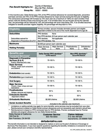
Grounding enteliBUS components in the sameenclosureWhen all enteliBUS components are in the same enclosure connect thepower port GND on the automation engine and on each expander tothe same earth ground, as shown in Figure 7. This recommendationapplies when the components are connected by their integrated eBUSnetwork connectors and when connected by eBUS network cable.I/O modules are grounded properly via the backplane they are pluggedinto.Figure 7: Grounding enteliBUS components in the same enclosureEnclosure24VACX224VACX2X1--- GND 24AutomationEngine--- GND 24Controller backplaneShield- -8-X1ExpanderExpander backplaneShield- eBB-TERM Terminator
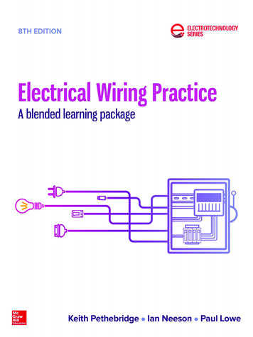
Wiring and Installation Guidelines, Edition 1.5Grounding Distributed enteliBUS ComponentsWhen enteliBUS components are distributed (within the limitations ofthe eBUS network) and not in the same enclosure, connect the powerport GND on the automation engine and on each expander to a localearth ground, as shown in Figure 8.I/O modules are grounded properly via the backplane they are pluggedinto.Power and ground must comply with following rules: Power for all components must be supplied from the sameelectrical service. All local earth grounds must be supplied from the sameelectrical service.Figure 8: Grounding Distributed enteliBUS ComponentsEnclosure24VACX2Power and ground for allcomponents must be suppliedfrom the same electrical service.X1--- GND 24AutomationEngineController backplaneShield- eBUS networkEnclosure24VACX2X1--- GND 24ExpanderExpander backplaneShield-eBB-TERM Terminator -9-
FusingWhen a transformer does not have a built-in circuit breaker, DeltaControls recommends using a slow-blow fuse on the secondary side ofthe transformer. The fuse size is determined by the VA ratings of thedevices. Use Table 4 to determine the correct fuse size. A fuse not onlyprovides protection for the transformer, but can also help withtroubleshooting.Table 4: Correct Fuse SizesTransformer RatingFuse Size100 VA4A75 VA3A50 VA2A25 VA1AWithout a fuse, the only protection a Class 2 circuit has is the primarycircuit breaker (normally 15 or 20 A). If a device were to fail, thiscircuit breaker is not sufficient protection to prevent damage to thetransformer. A fuse on the transformer’s secondary prevents damageto the device.Delta Controls Class 2 products have a maximum rating of 100 VA.This means that the maximum allowable fuse size is 4 A.Fuse one secondary transformer wire only. For half-wave devices, fusethe wire connected to the device’s 24 pin. For full-wave devices,either wire can be fused.Figure 9: Using 4 A Slow-blow FuseHalf-wave24 24 Correct24 GND24VAC4A Slow BlowFull-wave24VAC4A Slow Blow- 10 -Correct
Wiring and Installation Guidelines, Edition 1.5Multiple Service EntrancesA service entrance is a location where the electrical service enters t
Chapter 3 - RS-485 Network Installation Guidelines- covers the Delta Controls recommended design and installation specifications for a RS-485 network and aids the installer in building robust networks. Chapter 4 - Ethernet Network Installation Guidelines - provides a synopsis of Ethernet network wiring specifications and practices that