Transcription
This is a repository copy of Analytical transmission electron microscopy.White Rose Research Online URL for this : Accepted VersionArticle:Brydson, R, Brown, A, Benning, LG et al. (1 more author) (2014) Analytical transmissionelectron microscopy. Reviews in Mineralogy and Geochemistry, 78 (1). 219 - 269. ReuseUnless indicated otherwise, fulltext items are protected by copyright with all rights reserved. The copyrightexception in section 29 of the Copyright, Designs and Patents Act 1988 allows the making of a single copysolely for the purpose of non-commercial research or private study within the limits of fair dealing. Thepublisher or other rights-holder may allow further reproduction and re-use of this version - refer to the WhiteRose Research Online record for this item. Where records identify the publisher as the copyright holder,users can verify any specific terms of use on the publisher’s website.TakedownIf you consider content in White Rose Research Online to be in breach of UK law, please notify us byemailing eprints@whiterose.ac.uk including the URL of the record and the reason for the withdrawal terose.ac.uk/
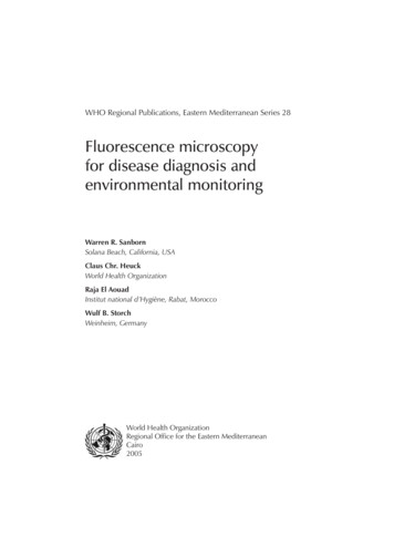
Reviews in Mineralogy & GeochemistryVol. 78 pp. XXX-XXX, 2013Copyright Mineralogical Society of America6Analytical Transmission Electron MicroscopyRik Brydson1, Andy Brown1, Liane G. Benning21Institute for Materials ResearchSchool of Earth and EnvironmentUniversity of LeedsLeeds, LS2 9JT, United Kingdom2R.M.Drummond-Brydson@leeds.ac.ukKen LiviHigh-Resolution Analytical Electron Microbeam FacilityIntegrated Imaging CenterDepartment of Earth and Planetary SciencesJohns Hopkins UniversityBaltimore, Maryland 21218, U.S.A.INTRODUCTIONAnalytical transmission electron microscopy (TEM) is used to reveal sub-micrometer,internal ine structure (the microstructure or ultrastructure) and chemistry in minerals. Theamount and scale of the information which can be extracted by TEM depends critically onfour parameters; the resolving power of the microscope (usually smaller than 0.3 nm); theenergy spread of the electron beam (of the order of an electron volt, eV); the thickness of thespecimen (almost always signiicantly less than 1 mm), and the composition and stability of thespecimen. An introductory text on all types of electron microscopy is provided by Goodhewet al. (2001), while more detailed information on transmission electron microscopy may befound in the comprehensive text of Williams and Carter (2009).INTRODUCTION TO ANALYTICALTRANSMISSION ELECTRON MICROSCOPY (TEM)Basic design of transmission electron microscopes (TEM)The two available modes of TEM—CTEM and STEM—differ principally in the waythey address the specimen. Conventional TEM (CTEM) is a wide-beam technique, in which aclose-to-parallel electron beam loods the whole area of interest and the image (or diffractionpattern), formed by an imaging (objective) lens after the thin specimen from perhaps 106-107pixels on a digital camera, is collected in parallel. Scanning TEM (STEM) deploys a inefocused beam, formed by a probe-forming lens before the thin specimen, to address each pixel(here, a dwell point) in series and form a sequential image as the probe is scanned across thespecimen. Figures 1 and 2 summarize these different instrument designs; here it should benoted that many modern TEM instruments are capable of operating in both modes, rather thanbeing instruments dedicated to one mode of operation.In both types of instrument analytical information from a small region is usually collectedusing a focused beam. The smallest region from which an analysis can be collected is deinedby the diameter of this beam and hence the corresponding through-thickness volume in the1529-6466/13/0078-0006 10.0078 06 Byrdson etal.indd 1http://dx.doi.org/10.2138/rmg.2013.78.67/17/2013 8:40:02 PM
Brydson, Brown, Benning, Livi2Figure 1. Schematic diagram of the layout of an analytical conventional transmission electron microscope(CTEM) itted with an energy dispersive X-ray (EDX) detector and an electron energy loss (EEL) spectrometer (after Brydson 2001, 2011). α and β denote the convergence and collection angles. Eo is incidentbeam energy, E is the energy loss of the fast electron and B is the magnetic ield in the spectrometer.specimen within which various elastic and inelastic scattering (energy-loss) processes takeplace.In both CTEM and STEM, electrons are produced from an electron emitter, focused andcollimated into a beam and inally accelerated to a given beam energy. Key instrumental components, which affect the microscope resolution and analytical performance, are: the electron emitter which can operate via either a thermionic or ield emissionmechanism or a combination of the two; ield emission provides the brightest, mostmonochromatic and coherent source of electrons. the accelerating voltage (Eo, typically in the range 60-300 kV) and hence incidentelectron energy; the higher the accelerating voltage the higher the resolution and thelarger the sample penetration (although, in certain cases depending on the elementspresent and their chemical bonding, sample damage via sputtering may be an issueabove a certain threshold energy).In the CTEM (Fig. 1), two or more electromagnetic condenser lenses demagnify the probeto a size typically between a few micrometers and a few nanometers—the excitation of theselenses controls both the beam diameter and the beam divergence/convergence angle. For these78 06 Byrdson etal.indd 27/17/2013 8:40:02 PM
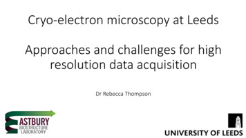
Analytical TEM3Figure 2. Schematic diagram of the layout of a dedicated analytical scanning transmission electron microscope (STEM) itted with an energy dispersive X-ray (EDX) detector and an electron energy-loss (EEL)spectrometer (after Brydson 2001, 2011). α and β denote the convergence and collection angles, respectively. Note this is a dedicated UHV STEM coniguration with the electron emitter at the base of the microscope for reasons of stability; in the more usual hybrid CTEM/STEM instruments, STEM mode is achievedusing the TEM condenser lens system (Fig. 1) which is prior to the specimen and is used to converge aprobe which is then scanned across the specimen.condenser-lens systems the irst condenser (C1 or spot size) controls the demagniication ofthe source, while the second (C2 or intensity) controls the size of the spot at the specimen andhence the beam divergence/convergence.The specimen is in the form of a thin ( 100 nm) 3 mm diameter disc of either the materialitself or the material supported on an electron transparent ilm. The specimen is usually insertedinto the vacuum of the TEM via an airlock and ixed into a side-entry specimen rod that can betranslated or tilted (about one or two axes).In the CTEM (see Fig. 1), the main electromagnetic objective lens forms the irstintermediate, real space, projection image of the illuminated specimen area (in the image planeof the lens) as well as the corresponding reciprocal space diffraction pattern (in the back focalplane of the lens). Here the image magniication relative to the specimen is typically 50-100times. For a given electron emitter and accelerating voltage, the image resolution in CTEMis principally determined by imperfections or aberrations in this objective lens. An objectiveaperture can be inserted in the back focal plane of the objective lens to limit beam divergencein reciprocal space of the transmitted electrons contributing to the magniied image. Typicallythere are a number of circular objective apertures ranging from 10 to 100 mm in diameter. Theprojector lens system consists of a irst projector or intermediate lens that focuses on eitherthe objective lens image plane (microscope operating in imaging mode) or the back focalplane (microscope in diffraction mode). The irst projector lens is followed by a series of threeor four further projector lenses—each of which magnify the image or diffraction pattern bytypically up to 20 times. The Selected Area Electron Diffraction (SAED) aperture usually liesin the image plane of one of the projector lenses (due to space considerations) and if projectedback to the irst intermediate image and hence the specimen effectively allows the selection ofa much smaller area (typically ranging from a few tenths of a micron to a few microns) on thespecimen for the purposes of forming a diffraction pattern. The overall microscope system canprovide a total magniication of up to a few million times on the electron luorescent microscope78 06 Byrdson etal.indd 37/17/2013 8:40:03 PM
Brydson, Brown, Benning, Livi4viewing screen or, below this, the camera (either a photographic plate or a phosphor coupled toa two dimensional charge coupled diode (CCD) array).In the STEM (see Fig. 2), as opposed to CTEM, there is usually only a condenser lenssystem, which is better called a probe-forming lens; confusingly in a STEM this is oftenreferred to as an objective lens—however, the important distinction from the case of CTEMis that this objective lens lies before the specimen. This lens system is used to form a smalldiameter (typically a nanometer or less) probe that is serially scanned in a two-dimensionalraster across the specimen. At each point the transmitted beam intensity is measured—thusbuilding up a serial image of the specimen. Two intensities are usually recorded: that fallingon an on-axis bright ield (BF) detector that collects electrons that have undergone relativelysmall angles of scattering (principally undiffracted, Bragg diffracted and inelastically scatteredelectrons which gives images equivalent to CTEM BF images), as well as that incident on ahigh-angle annular dark-ield (HAADF) detector that principally collects higher-angle (beyondthe diffracted spots) incoherently elastically scattered electrons (so called Z-contrast images).In a STEM instrument, the resolution of the scanned image (as well as the analytical resolutiondescribed above) is determined largely by the beam diameter generated by the probe-forminglens and this is also limited by lens aberrations. As discussed in the introduction, there are nowmany hybrid CTEM/STEM instruments, which can operate in both modes.Interactions between the electron beam and the specimenThe high-energy incident electron beam of the TEM interacts with the sample in anumber of ways. Low-angle, coherent elastic scattering (diffraction) of electrons (through1 -10 ) occurs via the interaction of the incident electrons with the electron cloud associatedwith atoms in a solid—this is used for CTEM and STEM bright ield imaging. High-angle,incoherent elastic (back)scattering (through 10-180 ) occurs via interaction of the negativelycharged electrons with the nuclei of atoms—this is used for STEM dark ield imaging. Thecross section or probability for elastic scattering varies roughly as the square of the meanatomic number of the sample, whereas inelastic scattering, which provides the analyticalsignal, generally involves much smaller scattering angles than is the case for elastic scattering;the cross section of inelastic scattering varies linearly with atomic number.Inelastic scattering of electrons by solids predominantly occurs via four major mechanisms:1.Phonon scattering, where the incident electrons excite phonons (atomic vibrations)in the material. Typically the energy loss is 1 eV, the scattering angle is quite large( 10 ) and for carbon, the average distance between such scattering events—the meanfree path, Λ—is 1 mm. This is the basis for heating of the specimen by an electronbeam.2.Plasmon scattering, where the incident electrons excite collective, ‘‘resonant’’ oscillations (plasmons) of the valence (bonding) electrons associated with a solid. Here, theenergy loss from the incident beam is between 5-30 eV and Λ is 100 nm, causing thisto be the dominant scattering process in electron-solid interactions.3.Single-electron excitation, where the incident electron transfers energy to single atomic electrons resulting in the ionization of atoms. The mean free path for this event isof the order of mm. Lightly bound valence electrons may be ejected from atoms and,if they escape from the specimen surface, may be used to form secondary electronimages in scanning electron microscopy (SEM). Energy losses for such excitationstypically range up to 50 eV. If inner-shell electrons are removed, the energy loss canbe up to keV. For example, the energy loss required to ionize carbon 1s (i.e., K shell)electrons is 284 eV. The energy loss of the incident beam can be used in electronenergy-loss spectroscopy (EELS) analysis and the secondary emissions (e.g., X-rayor Auger electron production; see Fig. 3) produced when the ionized atom relaxes can78 06 Byrdson etal.indd 47/17/2013 8:40:03 PM
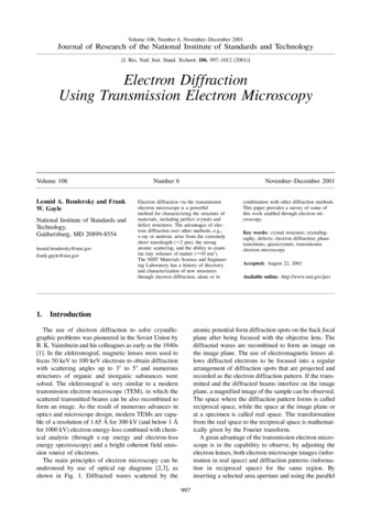
Analytical TEM5ABFigure 3. Energy dispersive X-ray analysis in the TEM (after Brydson 2011). De-excitation mechanismsfor an atom which has undergone K-shell ionization by primary electrons: (A) emission of a characteristicKα X-ray (the inset details possible ionization processes and emission of X-rays) and (B) emission of aKLM Auger electron.also be used for analytical purposes in the techniques of either energy dispersive orwavelength dispersive X-ray (EDX/WDX) spectroscopy.4.Direct radiation losses, the principal of which is Bremsstrahlung X-ray emissioncaused by the deceleration of electrons by the solid; this forms the background in theX-ray emission spectrum upon which are superimposed characteristic X-ray peaksproduced by single-electron excitation and subsequent relaxation. The Bremsstrahlung energy losses can take any value and can approach the total incident beam energy in the limit of full deceleration.Brief review of imaging mechanisms in CTEM and STEM. All TEM images are twodimensional projections of the internal structure of a thin specimen region. In recent years,however, there has been considerable interest in reconstructing the three dimensional nature ofthe specimen using tomographic techniques (see Weyland and Midgley (2007) in Hutchison78 06 Byrdson etal.indd 57/17/2013 8:40:03 PM
Brydson, Brown, Benning, Livi6and Kirkland (2007)). Notwithstanding, unless they are STEM EDX or EEL spectrum imagesor energy iltered CTEM images (see “EDX and EELS Imaging” section below), all TEMimages are based principally on the elastically scattered components of the incident electronbeam although the images may contain some underlying inelastically scattered contribution(Williams and Carter 2009).There are three basic contrast mechanisms which contribute to all CTEM images:1.Mass-thickness contrast: sample regions (whether amorphous or crystalline) that arethicker or of higher density will scatter the electrons more strongly and hence moreelectrons will be scattered through high angles and be lost in their passage down thenarrow bore of the microscope column so making these areas appear darker in the image.2.Diffraction contrast: crystalline regions of the sample oriented at the Bragg angle fordiffraction will excite diffracted beams, which correspondingly reduce the amplitudeof the unscattered beam. Insertion of an objective aperture in the back focal planecan accentuate this effect via formation of bright ield (BF) images (the unscatteredbeam selected with diffracting regions appearing dark) or dark ield (DF) images (adiffracted beam selected, with diffracting regions appearing bright). Any microstructural feature which changes the corresponding diffraction condition (such as a grainboundary, stacking fault, strain ield or a line defect etc.) will, in principle, show up indiffraction contrast.3.Phase contrast: this relies on the interference between the unscattered beam and different diffracted beams to produce an interference pattern (visible at high magniication) which relects the lattice periodicity; effectively lattice planes and hence atomicpositions are imaged but may appear light or dark depending on the microscope conditions (objective lens defocus, beam energy etc.) and the sample thickness.Some examples of these three CTEM contrast mechanisms are given in Figure 4A aswell as in many subsequent igures in the chapter. In addition to imaging, as discussed inthe Introduction, the diffraction pattern in the back focal plane may be viewed. The area ofthe specimen from which the diffraction pattern originates can be deined using the SAEDaperture (using effectively parallel illumination) or the probe can be converged to a small areaon the specimen so as to form diffraction discs (whose radius depends on the convergenceangle) rather than spots. The diffraction pattern allows the degree of crystallinity as well asthe exact crystallographic phase of the material to be determined as well as the incident beamdirection through the crystal. See Figure 4B for a schematic diagram and also Figures 16 and19 for an example diffraction patterns.STEM bright ield images contain all the same contrast mechanisms as CTEM bright ieldimages, whereas STEM dark ield images (particularly HAADF which relies on Rutherfordscattering from the nuclei) images are relatively insensitive to structure and orientation butstrongly dependent on atomic number (Z contrast), with the intensity varying as Zζ where ζlies between 1.5 and 2. If the specimen is uniformly thick in the area of interest the HAADFintensity can be directly related to the average atomic number in the column at each pixel.Figure 4C shows an example BF and DF STEM image. If the beam is less than one atomdimension in diameter, for instance in an aberration-corrected STEM (see later), then atomcolumn compositional resolution is therefore possible (strictly, only if we have strongchanneling of the probe down the atomic columns which occurs when the sample is orientedalong a low Miller index zone axis).Analytical signals. Based on the description in the section “Interactions between theelectron beam and the specimen”, the two major techniques for chemical nanoanalysis in the78 06 Byrdson etal.indd 67/17/2013 8:40:03 PM
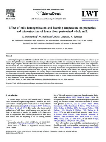
Analytical TEM7Figure 4AAFigure 4BBCFigure 4. (A) TEM bright ield image of a tubular halloysite clay mineral showing both CTEM mass thickness contrast (from the amorphous carbon support ilm and the halloysite tubes) and CTEM diffraction contrast from some of the halloysite tubes oriented at the Bragg angle for diffraction. At higher magniicationCTEM phase contrast is evident in the (002) basal plane lattice fringes of tube walls (Brydson and Hillier,unpublished). (B) Schematic diagram of the geometry of electron diffraction in the CTEM and the form of theselected area diffraction pattern for amorphous, polycrystalline and single crystal sample regions. Examplesof real diffraction patterns are shown in Figure 16 and subsequent igures. (C) Example of (left) a STEM BFimage and (right) a STEM high angle annular dark ield image from a cluster of iron storage proteins, ferritinmolecule mineral-cores (doped ferrihydrite) cores within a tissue section (see Pan et al. 2009).78 06 Byrdson etal.indd 77/17/2013 8:40:04 PM
Brydson, Brown, Benning, Livi8transmission electron microscope are both concerned with inelastic interactions and are basedon the analysis of either the energy or wavelength of the emitted X-rays (EDX or WDX), orthe direct energy losses of the incident electrons (EELS).As shown in Figure 5, X-rays produced when the electron probe interacts with thespecimen are most commonly detected from the incident surface using a low take-off angleEnergy Dispersive X-ray (EDX) detector (i.e., the detector is approximately in the same planeas the sample, some 20 to the horizontal), so as to allow the detector to be brought close to thesample and also to minimize the predominantly forward-peaked Bremsstrahlung backgroundcontribution to the X-ray emission spectrum. Even though the detector is inserted to within afew mm of the sample surface, it collects only a small proportion (usually only a few percent)of the isotropically emitted X-ray signal owing to the limited solid collection angle of thedetector (typically signiicantly less than 1 Steradian, from a total possible solid angle of4π Steradians). Generally, the specimen is tilted towards the detector (typically through ca.15 ) so as to provide a clear X-ray trajectory between the irradiated area and the detector.The volume of the specimen that produces X-rays is controlled by the electron probe size(and hence condenser-lens currents) as well as beam broadening within the specimen thatincreases with (among other things) thickness and average atomic number and decreases withFigure 5. Energy dispersive X-ray analysis in the TEM (after Brydson 2011). Schematic diagram showingthe components and location of an EDX detector in a TEM.78 06 Byrdson etal.indd 87/17/2013 8:40:04 PM
Analytical TEM9microscope accelerating voltage. High take-off angle X-ray detectors also exist and these donot require the specimen to be tilted towards the detector.Below the microscope viewing screen, the self-contained EELS spectrometer (whichalmost always possesses a variable entrance aperture itself) and detection system collectsthe transmitted electron signal that is composed of both elastically and inelastically scatteredelectrons. In both Figures 1 and 2, α and β are known as the convergence and collectionsemi-angles, respectively. Note certain commercial EELS systems (particularly those initiallydeveloped for the purposes of energy-iltered imaging) employ an in-column design with theEEL spectrometer placed between the objective and projector lenses. Further details are givenin the “EDX and EELS Imaging” section below.As discussed in the introduction, apart from the case of energy iltered CTEM (see “EDXand EELS Imaging” section below), analytical information is most usually collected using afocused probe. In this respect STEMs are ideal analytical machines since they easily allow thesimultaneous recording of images and X-ray emission spectra, furthermore retraction of thebright-ield detector allows electrons to enter an EEL spectrometer while still simultaneouslyrecording the HAADF image. Generally, STEMs can collect analytical EDX and EELS data inone of two ways: irstly, by scanning the beam over an area and collecting the signal from thewhole scanned area and, secondly, by scanning the beam slowly and recording the analyticalsignal serially at each point (known as spectrum imaging). Dedicated STEMs employ extremelysmall probe sizes produced by cold ield-emission electron sources that can provide extremelyhigh energy resolution (EELS) and high spatial resolution (EELS and EDX) measurements.The specimenA specimen suitable for study by analytical TEM should be thin enough for electrontransmission without signiicant spreading of the electron beam, yet be representative of thematerial about which we wish to draw conclusions. These simple requirements imply that inmost cases we must prepare a thin specimen (typically less than 50 nm for high resolutionstudies) from a larger sample, and in all cases we must assure ourselves that the processes ofpreparation, mounting and examination do not change, in any uncontrolled way, the importantfeatures of the specimen. Specimen preparation is therefore an absolutely crucial aspect ofanalytical TEM. This is discussed in the “Example of the practical application of EDX: clayminerals – Sample preparation” and “Developments in TEM specimen preparation” sectionsbelow. However, for the vast majority of mineralogical and geological samples this usuallyinvolves cleaving or crushing a sample in an agate mortar and pestle, dispersing in a suitableinert liquid and drop-casting onto a TEM grid with a thin, usually amorphous and often holeysupport ilm. An alternative procedure, which retains the microstructural relationships in theoverall specimen, involves the thinning and polishing of a bulk 3 mm disc of material cutusing a drill or ultrasonic disc cutter. Course-scale thinning of the disc is usually performedmechanically using standard polishing procedures employing silicon carbide, diamond andalumina or silica abrasives of progressively decreasing roughness. Final thinning to electrontransparency (ca. 100 nm) can be achieved via either: accurate and controlled mechanicalpolishing (tripod polishing); chemical polishing using jets of acids or alkalis or, very commonly,ion milling using a broad low energy argon ion beam. More recently the use of focused ionbeam (FIB) specimen preparation techniques, although not without their speciic problemsassociated with sample damage, has radically altered the preparation of thin TEM specimensfrom site-speciic areas within larger samples, in particular cross sections of interfaces andsurfaces (see Fig. 19 and also Giannuzzi 2004).When analyzing the sample, the specimen should resist both contamination and damageinduced by the primary electron beam. For a given incident beam energy, beam damage of thespecimen is generally a function of the energy deposited within the specimen volume (known78 06 Byrdson etal.indd 97/17/2013 8:40:05 PM
10Brydson, Brown, Benning, Livias dose) which is dependent on the incident energy of the electron beam, the interaction crosssection for the specimen, the electron luence (i.e., the total number of electrons incident perunit area of specimen) and, in some cases, the luence rate (usually quoted in current per unitarea) can be important. In many cases, for a given set of microscope conditions, there is a“safe” luence or luence rate below which damage is negligible.Beam damage of the specimen can occur by two dominant mechanisms: knock-ondamage in which an atom or ion is displaced from its normal site, and ionization damage (insome contexts called radiolysis) in which electrons are perturbed leading to chemical and thenpossibly structural changes (Egerton et al. 2004; Williams and Carter 2009). The latter canalso eventually result in specimen heating. Both types of damage are very dificult to predict orquantify with accuracy, because they depend on the bonding environment of the atoms in thespecimen. In most circumstances, however, the knock-on cross section increases with primarybeam energy, while the ionization cross section decreases. Thus there is a compromise to bestruck for each specimen to ind a beam energy that is low enough not to cause signiicantatomic displacement but is high enough to suppress radiolysis.Recent developments in analytical TEMAs mentioned previously, the image resolution in CTEM is primarily determined by theimperfections or aberrations in the objective lens, while in a STEM instrument the resolutionof the scanned image (as well as the analytical resolution for EDX and EELS) is determinedlargely by the beam diameter generated by the probe-forming lens which is also limited byaberrations. In both cases the most serious lens aberration is spherical aberration, wherebyelectrons travelling at differing distances from the central optic axis of the lens are focused todifferent positions. In recent years, technical dificulties have been overcome (principally dueto increases in computing power) which has allowed both the diagnosis and correction of anincreasing number (and type) of these lens aberrations (Hawkes 2008). Aberration correctioncould in principle be applied to any magnetic lens in any microscope. In practice there are twokey areas where it is employed (in some cases in tandem) to correct spherical aberration: (i)in the condenser/illumination or probe-forming system (STEM) and (ii) in the objective orimaging lens (CTEM). With the correction of spherical aberration, the next resolution-limitinglens aberration, particularly at low accelerating voltages, is chromatic aberration wherebyelectrons of differing energies are focused to different positions. At the time of writing there area number of schemes being developed and implemented for chromatic aberration correction(Leary and Brydson 2011). One of the main beneits of the correction of aberrations in STEMis in the reduction of the “beam tails” so that a ine beam positioned on a speciied column ofatoms does not “spill” signiicant electron intensity into neighboring columns. This has bigimplications for the STEM-based techniques of HAADF or “Z contrast” imaging, EELS andEDX analysis and even tomography (Brydson 2011).Particularly with the advent of micro-electromechanical systems (MEMS) technology, itis now becoming increasingly possible to control many environmental parameters associatedwith the specimen while in many cases simultaneously imaging or spectroscopically analyzinga region of interest. Possible in situ experiments that have been demonstrated include:specimen heating or cooling, specimen straining or compression, the control of local electricor magnetic ields, measurement of local specimen conductivity, illumination of the specimenwith photons, even imaging the specimen under the presence of environmental atmospheres ofgas or even (lowing) liquids (see chapter by Gai (2007) in Hutchison and Kirkland (2007)).Finally, as mentioned at the beginning of subsection “Brief review of imaging mechanismsin CTEM and STEM”, methodologies for three dimensional TEM image reconstructionsusing either tilt series tomography (see chapter by Weyland and Midgley (2007) in Hutchisonand Kirkland (2007)) or single particle analysis (Pan et al. 2009) have been applied in areas78 06 Byrdson etal.indd 107/17/2013 8:40:05 PM
Analytical TEM11potentially akin to geology and mineralogy. In terms of analytical TEM, the basic possibilitiesare any signal, which monotonically increases with increasing thickness such as HAADFimages and potentially EDX and EEL spectrum images or energy iltered TEM images(EFTEM) (see section below on “EDX and EELS imaging”).ELEMENTAL QUANTIFICATION – EDX AND EELSEDXAs discussed previously (section
Leeds, LS2 9JT, United Kingdom R.M.Drummond-Brydson@leeds.ac.uk Ken Livi High-Resolution Analytical Electron Microbeam Facility . Basic design of transmission electron microscopes (TEM) The two available modes of TEM—CTEM and STEM—differ principally in the way they address the specimen. Conventional TEM (CTEM) is a wide-beam technique, in .