Transcription
EDK Concepts, Tools,and TechniquesA Hands-On Guide to EffectiveEmbedded System DesignUG683 (v14.6) June 19, 2013This document applies to the following software versions: ISE Design Suite 14.6 through 14.7
Notice of DisclaimerThe information disclosed to you hereunder (the “Materials”) is provided solely for the selection and use of Xilinx products. To the maximumextent permitted by applicable law: (1) Materials are made available "AS IS" and with all faults, Xilinx hereby DISCLAIMS ALL WARRANTIESAND CONDITIONS, EXPRESS, IMPLIED, OR STATUTORY, INCLUDING BUT NOT LIMITED TO WARRANTIES OF MERCHANTABILITY, NONINFRINGEMENT, OR FITNESS FOR ANY PARTICULAR PURPOSE; and (2) Xilinx shall not be liable (whether in contract or tort, includingnegligence, or under any other theory of liability) for any loss or damage of any kind or nature related to, arising under, or in connection with,the Materials (including your use of the Materials), including for any direct, indirect, special, incidental, or consequential loss or damage(including loss of data, profits, goodwill, or any type of loss or damage suffered as a result of any action brought by a third party) even if suchdamage or loss was reasonably foreseeable or Xilinx had been advised of the possibility of the same. Xilinx assumes no obligation to correctany errors contained in the Materials or to notify you of updates to the Materials or to product specifications. You may not reproduce,modify, distribute, or publicly display the Materials without prior written consent. Certain products are subject to the terms and conditionsof the Limited Warranties which can be viewed at http://www.xilinx.com/warranty.htm; IP cores may be subject to warranty and supportterms contained in a license issued to you by Xilinx. Xilinx products are not designed or intended to be fail-safe or for use in any applicationrequiring fail-safe performance; you assume sole risk and liability for use of Xilinx products in Critical itapps. Copyright 2009-2013 Xilinx, Inc. Xilinx, the Xilinx logo, Artix, ISE, Kintex, Spartan, Virtex, Vivado, Zynq, and other designated brandsincluded herein are trademarks of Xilinx in the United States and other countries. All other trademarks are the property of their respectiveowners.Revision HistoryThe following table shows the revision history for this document.DateVersion07/25/201214.2RevisionBook release for ISE Design Suite 14.2 release. Modified Test Drives and figures as needed to match new software version. Added Chapter 8, “Creating a New Project Using the Vivado Design Suite.” Updated links in Appendix A, “Additional Resources.”10/16/201214.3Book release for ISE Design Suite 14.3 release. Minor updates to match GUI terminology changes. Updated links in Appendix A, “Additional Resources.”12/18/201214.4Book release for ISE Design Suite 14.4 release. Updated figures in Chapter 3. Corrected errors in “Take a Test Drive! Adding the Pcore to Your Project,” page 60.03/20/201314.5Book release for ISE Design Suite 14.5 release. Updated figures throughout document, where necessary. Minor updates in Chapter 5 to match changes in 14.5 release. Updated links in Appendix A, “Additional Resources.”06/19/201314.6Book release for ISE Design Suite 14.6 release. Updated Chapter 5, “Software Development Kit”. In addition to other revisions,modifications were made to reflect changes in SDK related to System Debugger. Other, minor changes in Chapter 2, “Creating a New Project”, Chapter 5, “SoftwareDevelopment Kit”, and Chapter 6, “Creating Your Own Intellectual Property”.EDK Concepts, Tools, and Techniqueswww.xilinx.comUG683 (v14.6) June 19, 2013
Table of ContentsRevision History . . . . . . . . . . . . . . . . . . . . . . . . . . . . . . . . . . . . . . . . . . . . . . . . . . . . . . . . . . . . . . . . . . . 2Chapter 1: IntroductionAbout This Guide . . . . . . . . . . . . . . . . . . . . . . . . . . . . . . . . . . . . . . . . . . . . . . . . . . . . . . . . . . . . . . . . . .How EDK Simplifies Embedded Processor Design . . . . . . . . . . . . . . . . . . . . . . . . . . . . . . . . . . . . . . . .How the EDK Tools Expedite the Design Process. . . . . . . . . . . . . . . . . . . . . . . . . . . . . . . . . . . . . . . . .What You Need to Set Up Before Starting . . . . . . . . . . . . . . . . . . . . . . . . . . . . . . . . . . . . . . . . . . . . . .3466Chapter 2: Creating a New ProjectThe Base System Builder . . . . . . . . . . . . . . . . . . . . . . . . . . . . . . . . . . . . . . . . . . . . . . . . . . . . . . . . . . . . 9A Note on the BSB and Custom Boards . . . . . . . . . . . . . . . . . . . . . . . . . . . . . . . . . . . . . . . . . . . . . . . 13What’s Next? . . . . . . . . . . . . . . . . . . . . . . . . . . . . . . . . . . . . . . . . . . . . . . . . . . . . . . . . . . . . . . . . . . . . 13Chapter 3: Using Xilinx Platform StudioWhat is XPS?. . . . . . . . . . . . . . . . . . . . . . . . . . . . . . . . . . . . . . . . . . . . . . . . . . . . . . . . . . . . . . . . . . . . .The XPS Software . . . . . . . . . . . . . . . . . . . . . . . . . . . . . . . . . . . . . . . . . . . . . . . . . . . . . . . . . . . . . . . . .XPS Tools . . . . . . . . . . . . . . . . . . . . . . . . . . . . . . . . . . . . . . . . . . . . . . . . . . . . . . . . . . . . . . . . . . . . . . .XPS Directory Structure . . . . . . . . . . . . . . . . . . . . . . . . . . . . . . . . . . . . . . . . . . . . . . . . . . . . . . . . . . . .What’s Next? . . . . . . . . . . . . . . . . . . . . . . . . . . . . . . . . . . . . . . . . . . . . . . . . . . . . . . . . . . . . . . . . . . . .1515212223Chapter 4: Working with Your Embedded PlatformWhat’s in a Hardware Platform?. . . . . . . . . . . . . . . . . . . . . . . . . . . . . . . . . . . . . . . . . . . . . . . . . . . . .Hardware Platform Development in Xilinx Platform Studio. . . . . . . . . . . . . . . . . . . . . . . . . . . . . . .The Hardware Platform in System Assembly View . . . . . . . . . . . . . . . . . . . . . . . . . . . . . . . . . . . . . .What’s Next? . . . . . . . . . . . . . . . . . . . . . . . . . . . . . . . . . . . . . . . . . . . . . . . . . . . . . . . . . . . . . . . . . . . .25252629Chapter 5: Software Development KitAbout SDK. . . . . . . . . . . . . . . . . . . . . . . . . . . . . . . . . . . . . . . . . . . . . . . . . . . . . . . . . . . . . . . . . . . . . . . 31More on the Software Development Kit: Edit, Debug, and Release . . . . . . . . . . . . . . . . . . . . . . . . 36What’s Next? . . . . . . . . . . . . . . . . . . . . . . . . . . . . . . . . . . . . . . . . . . . . . . . . . . . . . . . . . . . . . . . . . . . . 44Chapter 6: Creating Your Own Intellectual PropertyUsing the CIP Wizard . . . . . . . . . . . . . . . . . . . . . . . . . . . . . . . . . . . . . . . . . . . . . . . . . . . . . . . . . . . . . . 45EDK Concepts, Tools, and TechniquesUG683 (v14.6) June 19, 2013www.xilinx.com1
Example Design Description . . . . . . . . . . . . . . . . . . . . . . . . . . . . . . . . . . . . . . . . . . . . . . . . . . . . . . . . 57Modifying the Template Files . . . . . . . . . . . . . . . . . . . . . . . . . . . . . . . . . . . . . . . . . . . . . . . . . . . . . . . 57Chapter 7: Working with Project NavigatorProject Navigator Overview . . . . . . . . . . . . . . . . . . . . . . . . . . . . . . . . . . . . . . . . . . . . . . . . . . . . . . . . 65Chapter 8: Creating a New Project Using the Vivado Design SuiteVivado Design Suite Overview . . . . . . . . . . . . . . . . . . . . . . . . . . . . . . . . . . . . . . . . . . . . . . . . . . . . . . 71Exporting Your Hardware Platform . . . . . . . . . . . . . . . . . . . . . . . . . . . . . . . . . . . . . . . . . . . . . . . . . . 75Appendix A: Additional ResourcesXilinx Resources . . . . . . . . . . . . . . . . . . . . . . . . . . . . . . . . . . . . . . . . . . . . . . . . . . . . . . . . . . . . . . . . . . 77EDK Documentation. . . . . . . . . . . . . . . . . . . . . . . . . . . . . . . . . . . . . . . . . . . . . . . . . . . . . . . . . . . . . . . 77EDK Additional Resources . . . . . . . . . . . . . . . . . . . . . . . . . . . . . . . . . . . . . . . . . . . . . . . . . . . . . . . . . . 77EDK Concepts, Tools, and TechniquesUG683 (v14.6) June 19, 2013www.xilinx.com2
Chapter 1IntroductionAbout This GuideThe Xilinx Embedded Development Kit (EDK) is a suite of tools and Intellectual Property(IP) that enables you to design a complete embedded processor system for implementationin a Xilinx Field Programmable Gate Array (FPGA) device.This guide describes the design flow for developing a custom embedded processingsystem using EDK. Some background information is provided, but the main focus is on thefeatures of and uses for EDK.Read this guide if you: Need an introduction to EDK and its utilities Have not recently designed an embedded processor system Are in the process of installing the Xilinx EDK tools Would like a quick reference while designing a processor systemNote: This guide is written for the Windows operating system. Linux behavior or the graphical userinterface (GUI) display might vary slightly.Take a Test Drive!The best way to learn a software tool is to use it, so this guide provides opportunities foryou to work with the tools under discussion. Specifications for a sample project are givenin the Test Drive sections, along with an explanation of what is happening behind the sceneand why you need to do it. This guide also covers what happens when you run automatedfunctions.Test Drives are indicated by the car icon, as shown beside the heading above.Additional DocumentationLinks to more detailed documentation on EDK is available in Appendix A, “AdditionalResources.”EDK Concepts, Tools, and TechniquesUG683 (v14.6) June 19, 2013www.xilinx.comSend Feedback3
Chapter 1: IntroductionHow EDK Simplifies Embedded Processor DesignEmbedded systems are complex. Getting the hardware and software portions of anembedded design to work are projects in themselves. Merging the two design componentsso they function as one system creates additional challenges. Add an FPGA design projectto the mix, and the situation has the potential to become very complicated indeed.To simplify the design process, Xilinx offers several sets of tools. It is a good idea to get toknow the basic tool names, project file names, and acronyms for these tools. You can findEDK-specific terms in the Xilinx Glossary. A link to this document is located inAppendix A, “Additional Resources.”The Integrated Design Suite, Embedded EditionXilinx offers a broad range of development system tools, collectively called the ISE Design Suite. For embedded system development, Xilinx offers the Embedded Edition ofthe ISE Design Suite. The Embedded Edition comprises: Integrated Software Environment (ISE) tools PlanAhead design analysis software ChipScope Pro (which is useful for on-chip debugging of FPGA designs) Embedded Development Kit (EDK). EDK is also available with the ISE Design Suite:System Edition, which includes tools for DSP design.For information on how to use the ISE tools for FPGA design, refer to the Xilinxdocumentation web page. A link to this page is located in Appendix A, “AdditionalResources.”The PlanAhead Design ToolThe PlanAhead design tool is the new tool offering by Xilinx. It targets complete systemdesign, simulation, implementation, and debug in a single interface. It supersedes ProjectNavigator and streamlines the entire hardware design flow.The Embedded Development Kit (EDK)The Embedded Development Kit (EDK) is a suite of tools and IP that you can use to designa complete embedded processor system for implementation in a Xilinx FPGA device.Xilinx Platform Studio (XPS)Xilinx Platform Studio (XPS) is the development environment used for designing thehardware portion of your embedded processor system. You can run XPS in batch mode orusing the GUI, which is what we will be demonstrating in this guide. XPS is nowintegrated with PlanAhead tools, making development easier.Software Development Kit (SDK)The Software Development Kit (SDK) is an integrated development environment,complementary to XPS, that is used for C/C embedded software application creationand verification. SDK is built on the Eclipse open-source framework and might appearfamiliar to you or members of your design team. For more information about the Eclipsedevelopment environment, refer to http://www.eclipse.org.4Send Feedbackwww.xilinx.comEDK Concepts, Tools, and TechniquesUG683 (v14.6) June 19, 2013
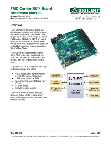
How EDK Simplifies Embedded Processor DesignOther EDK ComponentsOther EDK components include: Hardware IP for the Xilinx embedded processors Drivers and libraries for the embedded software development GNU compiler and debugger for C/C software development targeting theMicroBlaze and PowerPC processors Documentation Sample projectsEDK is designed to assist in all phases of the embedded design process.X-Ref Target - Figure 1-1Figure 1-1:EDK Concepts, Tools, and TechniquesUG683 (v14.6) June 19, 2013Basic Embedded Design Process Flowwww.xilinx.comSend Feedback5
Chapter 1: IntroductionHow the EDK Tools Expedite the Design ProcessFigure 1-1, page 5 shows the simplified flow for an embedded design.Typically, the ISE Design Tools development software is used to add an EmbeddedProcessor source, which is then created in XPS using the Base System Builder. You use XPS for embedded processor hardware system development. Specification ofthe microprocessor, peripherals, and the interconnection of these components, alongwith their respective detailed configuration, takes place in XPS. You use SDK for software development. SDK is also available as a standaloneapplication. It can be purchased and used without any other Xilinx tools installed onthe machine on which it is loaded. You can verify the correct functionality of your hardware platform by running thedesign through a Hardware Description Language (HDL) simulator. You can use theXilinx simulator ISim to simulate embedded designs.Three types of simulation are supported for embedded systems:-Behavioral-Structural-Timing-accurateYou can simulate your project in either XPS or Project Navigator. When you start yourdesign in Project Navigator, it automatically sets up the verification process structure.After your FPGA is configured with the bitstream containing the embedded design, youcan download and debug the Executable and Linkable Format (ELF) file from yoursoftware project from within SDK.For more information on the embedded design process as it relates to XPS, see the “DesignProcess Overview” in the Embedded System Tools Reference Manual. A link to this documentis provided in Appendix A, “Additional Resources.”What You Need to Set Up Before StartingBefore discussing the tools in depth, it would be a good idea to make sure they are installedproperly and that the environments you set up match required for the “Test Drive”sections of this guide.Installation Requirements: What You Need to Run EDK ToolsISE and VivadoEDK installationrequirementsISE design tools and Vivado design tools are both included in the ISE Design Suite,Embedded Edition software. Be sure the software, along with the latest update, is installed.Visit http://support.xilinx.com to confirm that you have the latest software versions.Whether you use ISE Design Suite or Vivado Design Suite for your design, you will use theEDK software for your embedded design. EDK includes both XPS and SDK.6Send Feedbackwww.xilinx.comEDK Concepts, Tools, and TechniquesUG683 (v14.6) June 19, 2013
What You Need to Set Up Before StartingSoftware LicensingXilinx software uses FLEXnet licensing. When the software is first run, it performs a licenseverification process. If it does not find a valid license, the license wizard guides youthrough the process of obtaining a license and ensuring that the Xilinx tools can use thelicense. If you are only evaluating the software, you can obtain an evaluation license.For more information about licensing Xilinx software, refer to the ISE Design Suite 14:Release Notes, Installation, and Licensing. A link to this document is located in Appendix A,“Additional Resources.”Simulation Installation RequirementsTo perform simulation using the EDK tools, you must have an appropriate Secure-IPcapable mixed-language simulator installed and simulation libraries compiled.Note: If you’re using ISim, the simulation libraries are already compiled.Supported simulators include: For Linux Enterprise Edition:-ModelSim v10.1a-Incisive Enterprise Simulator (IES) v11.1 or later.-Synopsys Verilog Compiler Simulator (VCS) and VCS 2011.12-ISim simulator (used in this tutorial)For Windows:-ModelSim v10.1a-ISim simulator (used in this tutorial)You can optionally use AXI Bus Functional Model (BFMs) to run BFM Simulation. Youmust have an AXI BFM license to use this utility. For more information about using AXIBFMs for embedded designs with XPS, refer to the AXI Bus Functional Models v1.9 datasheet (DS824).SimulationinstallationrequirementsFor information about the installation process, refer to the ISE Design Suite 14: Release Notes,Installation, and Licensing.Links to these resources are available in Appendix A, “Additional Resources.”Hardware Requirements for this GuideThis tutorial is based on the Kintex -7 KC705 FPGA Evaluation Board and cables.If you have an older board, refer to the appropriate version of this manual by going tohttp://www.xilinx.com/support/documentation/dt edk.htm and selecting a softwarerelease.EDK Concepts, Tools, and TechniquesUG683 (v14.6) June 19, 2013www.xilinx.comSend Feedback7
Chapter 1: Introduction8Send Feedbackwww.xilinx.comEDK Concepts, Tools, and TechniquesUG683 (v14.6) June 19, 2013
Chapter 2Creating a New ProjectNow that you’ve been introduced to the Xilinx Embedded Development Kit (EDK), you’llbegin looking at how to use it to develop an embedded system.The Base System BuilderAbout the BSBThe Base System Builder (BSB) is a wizard in the Xilinx Platform Studio (XPS) software thatquickly and efficiently establishes a working design. You can then customize your design.At the end of this section, you will have the opportunity to begin your first Test Drive,using the BSB to create a project.Why Use the BSB?Xilinx recommends using the BSB wizard to create the foundation for any new embeddeddesign project. While the wizard might be all you need to create your design, if you requiremore customization, the BSB saves you time by automating common hardware andsoftware platform configuration tasks. After running the wizard, you have a workingproject that contains all the basic elements needed to build more customized or complexsystems.What You Can Do in the BSB WizardUse the BSB wizard to select and configure a processor and I/O interfaces, add internalperipherals, and generate a system summary report.The BSB recognizes the system components and configurations on the selected board, andprovides the options appropriate to your selections.When you create the files, you have the option of applying settings from another projectyou have created with the BSB.Selecting a Board TypeThe BSB requires the selection of an available development board, or a custom board.Supported development boards can be selected in Project Navigator, or if starting in XPS,in the BSB introduction screens.EDK Concepts, Tools, and TechniquesUG683 (v14.6) June 19, 2013www.xilinx.comSend Feedback9
Chapter 2: Creating a New ProjectSupported BoardsSelecting a boardtypeYou can target one of the supported embedded processor development boards availablefrom Xilinx or one of its partners. When you have chosen among the peripherals availableon your selected board, the BSB creates a user constraints (UCF) file that includes pinoutsfor the peripherals you selected. The UCF file contains functional default values that arepre-selected in Xilinx Platform Studio (XPS). You can further enhance this base-levelproject in XPS and implement it with utilities provided by the ISE tools.When you first install EDK, only Xilinx board files are installed. To target a third partyboard, you must add the necessary board support files. The BSB Board Selection screencontains a link that helps you find third party board support files. After the files areinstalled, the BSB drop-down menus display those boards as well.Custom BoardsIf you are developing a design for a custom board, the BSB lets you select and interconnectone of the available processor cores (MicroBlaze or PowerPC processors, depending onyour selected target FPGA device) with a variety of compatible and commonly usedperipheral cores from the IP library. This gives you a hardware system to use as a startingpoint. You can add more processors and peripherals, if needed. The utilities provided inXPS assist with this, including the creation of custom peripherals.Selecting an Interconnect TypeYou can create an Advanced eXtensible Interface (AXI) system or a PLB system in the BaseSystem Builder.Selecting and Configuring a ProcessorYou can select the following for your MicroBlaze or PowerPC processor.Note: PowerPC processors are available only for version 4 and 5 devices. Single-processor system or dual-processor system (for MicroBlaze processors) External reference clock frequency Reset polarity Cache setup (this is configurable if DDR is selected) Floating Point Unit (FPU) settingSelecting and Configuring Multiple I/O InterfacesThe BSB wizard understands the external memory and I/O devices available on yourpredefined board and allows you to customize commonly used parameters for eachperipheral.You can open data sheets for external memory and I/O devices from within the BSBwizard.Adding Internal PeripheralsYou can add additional peripherals in the BSB wizard. The peripherals must be supportedby the selected board and FPGA device architecture. For a custom board, only certainperipherals are available for general selection and automatic system connection.10Send Feedbackwww.xilinx.comEDK Concepts, Tools, and TechniquesUG683 (v14.6) June 19, 2013
The Base System BuilderViewing a System Summary PageAfter you make your selections in the wizard, the BSB displays a system summary page. Atthis point, you can choose to generate the project, or you can go back to any previouswizard screen and revise the settings.Device and boardselections used inTest DrivesThis guide uses a Kintex -7-based KC705 Starter Board and targets a MicroBlazeprocessor. The options you select are listed in “Take a Test Drive! Creating a NewEmbedded Project,” page 11.Setting Up SoftwareThe Software Development Kit (SDK) is required for software development, and you’llhave the chance to try it as you work through this guide. Sample C applications used inSoftware Debug Test Drives are generated in SDK.The BSB Wizard and the PlanAhead ToolThe following test drive walks you through starting your new project in the PlanAhead design tool and using the New Project wizard to create your project.Take a Test Drive! Creating a New Embedded ProjectFor this test drive, you will start the PlanAhead tool and create a project with an embeddedprocessor system as the top level.1.Start the PlanAhead design tool.2.In the Welcome window, select Create New Project.3.Use the information in the table below to make your selections in the wizard screens.Wizard ScreenProject NameProject TypeSystem PropertySetting or Command to UseProject nameChoose a name and locationfor your project.Create Project SubdirectoryLeave this option checked.Select the type of source to import.RTL ProjectAdd SourcesThis is optional; no changes needed for this example.Add Existing IPOptional; no changes needed.Add ConstraintsOptional; no changes needed.Default PartSpecifySelect Boards.Board listSelect Kintex-7 KC705Evaluation Platform.New Project SummaryReview the project settings.When you click Finish, the New Project Wizard closes and a blank KC705 PlanAheaddesign tool project opens.4.Verify the FPGA part, target language, and simulator settings by clicking ProjectSettings in the Flow Navigator panel.EDK Concepts, Tools, and TechniquesUG683 (v14.6) June 19, 2013www.xilinx.comSend Feedback11
Chapter 2: Creating a New Project5.To add an EDK project, in the Sources panel, right-click Design Sources and selectAdd Sources.Note: You can also use shortcut Alt A.The Add Sources wizard opens.6.Click Add or Create Embedded Sources and click Next.Note: You can also click Alt M to select this option.7.Click Create Sub-Design.8.In the dialog box that opens, type system for the module name and click OK.9.Click Finish.The PlanAhead design tool creates your embedded design source project. It recognizesthat you have an embedded processor system and starts XPS.Next, you’ll use the BSB wizard to create a Base System in XPS.1.In the dialog box opens to ask if you want to create a Base System using the BSBwizard, click Yes.The first window of the BSB asks you to elect whether to create an AXI-based or PLBbased system.2.Select AXI system and click OK.3.In the Base System Builder wizard, create a project using the settings described in thefollowing table. If no setting or command is indicated in the table, accept the defaultvalues.Wizard ScreensBoard and SystemSelectionSystem PropertyBoardSetting or Command to UseUse the default option to create a system for theKintex-7 KC705 Evaluation Platform.Note: This is pre-populated because you selectedthis board in the PlanAhead tool.BoardConfigurationThis information is pre-populated based on yourboard selection.Note: If you had selected to create a system for acustom board, these fields would be editable.12Send FeedbackSelect a SystemSingle MicroBlaze Processor SystemOptimizationStrategyAreawww.xilinx.comEDK Concepts, Tools, and TechniquesUG683 (v14.6) June 19, 2013
A Note on the BSB and Custom BoardsWizard ScreensProcessor, Cache,and PeripheralConfiguration4.System PropertySetting or Command to UseProcessorFrequency100 MHz (default)Select aProcessormicroblaze 0Enable FloatingPoint UnitDo not enable this setting.Local MemorySize64 KBInstructionCache Size8 KBData Cache Size8 KBSelect andConfigurePeripherals Remove QSPI FLASH from the IncludedPeripherals list.To generate your design, click Finish.Read and then dismiss any dialog boxes that open after you exit the BSB Wizard.A Note on the BSB and Custom BoardsIf you plan to create a project that includes a customer board, you can create a Xilinx BoardDescription file (*.xbd2) file. The .xbd2 file: Defines the supported interfaces of a given board, system, or sub-system Enables you to create a system-level design through the Base System BuilderFor more information about using .xbd2 files, refer to the “Microprocessor PeripheralDefinition Translation tool (MPDX) chapter in the Embedded System Tools Reference Manual(UG111). A link to this document is provided in Appendix A, “Additional Resources.”What’s Next?The upcoming sections address Hardware Fundamentals. In Chapter 3, “Using Xilinx Platform Studio,” you will use the XPS software. In Chapter 4, “Working with Your Embedded Platform,” you will continue with thehardware design and learn how you can view and modify your new project in XPS.EDK Concepts, Tools, and TechniquesUG683 (v14.6) June 19, 2013www.xilinx.comSend Feedback13
Chapter 2: Creating a New Project14Send Feedbackwww.xilinx.comEDK Concepts, Tools, and TechniquesUG683 (v14.6) June 19, 2013
Chapter 3Using Xilinx Platform StudioNow that you have created a baseline project with the Base System Builder (BSB) wizard,it’s time to take a look at the options available in Xilinx Platform Studio (XPS). Using XPS,you can build on the project you created using the BSB. This chapter takes you on a tour ofXPS, and subsequent chapters describe how to use XPS to modify your design.Note: Taking the tour of XPS provided in this chapter is recommended. It enables you to follow therest of this guide and other documentation on XPS more easily.What is XPS?XPS includes a software interface that provides a set of tools to aid in project design. Thischapter describes the XPS software and some of the most commonly used tools.The XPS SoftwareFrom the XPS software, you can design a complete embedded processor system forimplementation within a Xilinx FPGA device. The XPS main window is shown in thefollowing figure.Optional Test Drives are provided in this chapter so you can explore the information andtools available in each of the XPS main window areas.EDK Concepts, Tools, and TechniquesUG683 (v14.6) June 19, 2013www.xilinx.comSend Feedback15
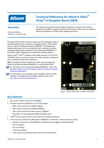
Chapter 3: Using Xilinx Platform StudioFigure X-Ref Target - Figure 3-1Figure 3-1:Using the XPS userinterfaceXPS Project WindowThe XPS main window is divided into these three areas: Project Information Area (1) Console Window (2) System Assembly View (3)The XPS main window also has labels to identify the following areas:16 Connectivity Panel (4) View Buttons (5) Filters Pane (6)Send Feedbackwww.xilinx.comEDK Concepts, Tools, and TechniquesUG683 (v14.6) June 19, 2013
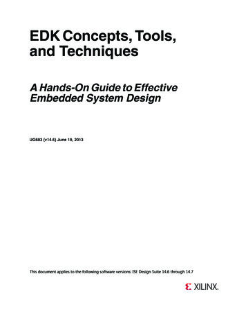
The XPS SoftwareProject Information AreaThe Project Information Area offers control of and information about your project. TheProject Information Area includes the Project and IP Catalog tabs.Project TabThe Project Tab, shown in Figure 3-2, contains information on the current project,including important project files and implementation settings.Figure X-Ref Target - Figure 3-2Figure 3-2:EDK Concepts, Tools, and TechniquesUG683 (v14.6) June 19, 2013Project Information Area, Project Tabwww.xilinx.comSend Feedback17
Chapter 3: Using Xilinx Platform StudioIP Catalog TabThe IP catalog tab is shown in Figure 3-3.X-Ref Target - Figure 3-3sFigure 3-3:IP Catalog TabThe IP Catalog tab lists information about the IP cores, including: Core name and licensing status (not licensed, locked, or unlocked) Release version and statu
The Embedded Development Kit (EDK) is a suite of tools and IP that you can use to design a complete embedded processor system for implementation in a Xilinx FPGA device. . Typically, the ISE Design Tools development software is used to add an Embedded Processor source, which is then created in XPS using the Base System Builder. .