Transcription
10G Ethernet PCS/PMAv6.0LogiCORE IP Product GuideVivado Design SuitePG068 October 5, 2016
Table of ContentsIP FactsChapter 1: OverviewApplications . . . . . . . . . . . . . . . . . . . . . . . . . . . . . . . . . . . . . . . . . . . . . . . . . . . . . . . . . . . . . . . . . . . . . . 7Unsupported Features. . . . . . . . . . . . . . . . . . . . . . . . . . . . . . . . . . . . . . . . . . . . . . . . . . . . . . . . . . . . . . 8Licensing and Ordering Information . . . . . . . . . . . . . . . . . . . . . . . . . . . . . . . . . . . . . . . . . . . . . . . . . . . 8Chapter 2: Product SpecificationStandards . . . . . . . . . . . . . . . . . . . . . . . . . . . . . . . . . . . . . . . . . . . . . . . . . . . . . . . . . . . . . . . . . . . . . . .Performance. . . . . . . . . . . . . . . . . . . . . . . . . . . . . . . . . . . . . . . . . . . . . . . . . . . . . . . . . . . . . . . . . . . . .Resource Utilization. . . . . . . . . . . . . . . . . . . . . . . . . . . . . . . . . . . . . . . . . . . . . . . . . . . . . . . . . . . . . . .Port Descriptions . . . . . . . . . . . . . . . . . . . . . . . . . . . . . . . . . . . . . . . . . . . . . . . . . . . . . . . . . . . . . . . . .Register Space . . . . . . . . . . . . . . . . . . . . . . . . . . . . . . . . . . . . . . . . . . . . . . . . . . . . . . . . . . . . . . . . . . .1010121232Chapter 3: Designing with the CoreGeneral Design Guidelines . . . . . . . . . . . . . . . . . . . . . . . . . . . . . . . . . . . . . . . . . . . . . . . . . . . . . . . . .Clocking. . . . . . . . . . . . . . . . . . . . . . . . . . . . . . . . . . . . . . . . . . . . . . . . . . . . . . . . . . . . . . . . . . . . . . . . .Resets . . . . . . . . . . . . . . . . . . . . . . . . . . . . . . . . . . . . . . . . . . . . . . . . . . . . . . . . . . . . . . . . . . . . . . . . . .Shared Logic . . . . . . . . . . . . . . . . . . . . . . . . . . . . . . . . . . . . . . . . . . . . . . . . . . . . . . . . . . . . . . . . . . . . .Interfacing to the Core. . . . . . . . . . . . . . . . . . . . . . . . . . . . . . . . . . . . . . . . . . . . . . . . . . . . . . . . . . . . .DRP Interface . . . . . . . . . . . . . . . . . . . . . . . . . . . . . . . . . . . . . . . . . . . . . . . . . . . . . . . . . . . . . . . . . . . .Receiver Termination. . . . . . . . . . . . . . . . . . . . . . . . . . . . . . . . . . . . . . . . . . . . . . . . . . . . . . . . . . . . . .Special Design Considerations . . . . . . . . . . . . . . . . . . . . . . . . . . . . . . . . . . . . . . . . . . . . . . . . . . . . . .7677828285969898Chapter 4: Design Flow StepsCustomizing and Generating the Core . . . . . . . . . . . . . . . . . . . . . . . . . . . . . . . . . . . . . . . . . . . . . . .Constraining the Core . . . . . . . . . . . . . . . . . . . . . . . . . . . . . . . . . . . . . . . . . . . . . . . . . . . . . . . . . . . .Simulation . . . . . . . . . . . . . . . . . . . . . . . . . . . . . . . . . . . . . . . . . . . . . . . . . . . . . . . . . . . . . . . . . . . . .Synthesis and Implementation . . . . . . . . . . . . . . . . . . . . . . . . . . . . . . . . . . . . . . . . . . . . . . . . . . . . .103108110111Chapter 5: Detailed Example DesignExample Design and Core Support Layer . . . . . . . . . . . . . . . . . . . . . . . . . . . . . . . . . . . . . . . . . . . . . 112Shared Logic and the Core Support Layer . . . . . . . . . . . . . . . . . . . . . . . . . . . . . . . . . . . . . . . . . . . . 11310G Ethernet PCS/PMA v6.0PG068 October 5, 2016www.xilinx.comSend Feedback2
Chapter 6: Test BenchAppendix A: Verification, UNH Testing, and InteroperabilitySimulation . . . . . . . . . . . . . . . . . . . . . . . . . . . . . . . . . . . . . . . . . . . . . . . . . . . . . . . . . . . . . . . . . . . . . 115Hardware Verification . . . . . . . . . . . . . . . . . . . . . . . . . . . . . . . . . . . . . . . . . . . . . . . . . . . . . . . . . . . . 115Testing . . . . . . . . . . . . . . . . . . . . . . . . . . . . . . . . . . . . . . . . . . . . . . . . . . . . . . . . . . . . . . . . . . . . . . . . 116Appendix B: Migrating and UpgradingMigrating . . . . . . . . . . . . . . . . . . . . . . . . . . . . . . . . . . . . . . . . . . . . . . . . . . . . . . . . . . . . . . . . . . . . . . 117Upgrading in the Vivado Design Suite . . . . . . . . . . . . . . . . . . . . . . . . . . . . . . . . . . . . . . . . . . . . . . . 117Appendix C: DebuggingFinding Help on Xilinx.com . . . . . . . . . . . . . . . . . . . . . . . . . . . . . . . . . . . . . . . . . . . . . . . . . . . . . . . .Debug Tools . . . . . . . . . . . . . . . . . . . . . . . . . . . . . . . . . . . . . . . . . . . . . . . . . . . . . . . . . . . . . . . . . . . .Simulation Debug. . . . . . . . . . . . . . . . . . . . . . . . . . . . . . . . . . . . . . . . . . . . . . . . . . . . . . . . . . . . . . . .Hardware Debug . . . . . . . . . . . . . . . . . . . . . . . . . . . . . . . . . . . . . . . . . . . . . . . . . . . . . . . . . . . . . . . .121122124125Appendix D: Additional Resources and Legal NoticesXilinx Resources . . . . . . . . . . . . . . . . . . . . . . . . . . . . . . . . . . . . . . . . . . . . . . . . . . . . . . . . . . . . . . . . .References . . . . . . . . . . . . . . . . . . . . . . . . . . . . . . . . . . . . . . . . . . . . . . . . . . . . . . . . . . . . . . . . . . . . .Revision History . . . . . . . . . . . . . . . . . . . . . . . . . . . . . . . . . . . . . . . . . . . . . . . . . . . . . . . . . . . . . . . . .Please Read: Important Legal Notices . . . . . . . . . . . . . . . . . . . . . . . . . . . . . . . . . . . . . . . . . . . . . . .10G Ethernet PCS/PMA v6.0PG068 October 5, 2016www.xilinx.comSend Feedback1321321331343
IP FactsIntroductionLogiCORE IP Facts TableThe LogiCORE IP 10G Ethernet PhysicalCoding Sublayer/Physical Medium Attachment(PCS/PMA) core forms a seamless interfacebetween the Xilinx 10G Ethernet Media AccessController (MAC) core and a 10 Gb/s-capablePHY, enabling the design of high-speedEthernet systems and subsystems.Designed to 10 Gigabit Ethernet specificationIEEE Standard 802.3-2012 clause 49, 72, 73,74 Optional Management Data Interface(MDIO) to manage PCS/PMA registers Supports 10GBASE-SR, -LR and -ER opticallinks in Zynq-7000, UltraScale , Virtex-7,and Kintex-7 devices (LAN mode only) SupportedDeviceFamily (1) (2)10GBASE-R: UltraScale Zynq -7000 All Programmable SoCVirtex -7, Kintex -7(3)10GBASE-KR: UltraScale ,Virtex-7(4)Supported UserInterfacesResourcesMDIO, XGMIIPerformance and Resource Utilization web pageProvided with CoreFeatures Core SpecificsSupports 10GBASE-KR backplane links inUltraScale, and Virtex-7 devices, includingAuto-Negotiation (AN), Training andForward Error Correction (FEC)10 Gigabit Ethernet Media IndependentInterface (XGMII) connects seamlessly tothe Xilinx 10 Gigabit Ethernet MACA 64-bit or 32-bit data width option isavailable for the 10GBASE-R standard. The10GBASE-KR standard is always providedwith a 64-bit data width.Design FilesEncrypted RTLExample DesignVerilog and VHDLTest BenchVerilog and VHDLConstraints FileXilinx Design Constraint (XDC)SimulationModelVerilog or VHDL source HDL ModelSupportedS/W DriverSee the 10 Gigabit Ethernet Subsystem ProductGuide (PG157) [Ref 3]Tested Design Flows(5)Design EntrySimulationVivado Design SuiteFor supported simulators, see theXilinx Design Tools: Release Notes Guide.SynthesisVivado SynthesisSupportProvided by Xilinx at the Xilinx Support web pageNotes:1. Some packages and speedgrades might not support the10 Gb/s line rate. For a complete list of supported devices, seethe Vivado IP catalog. For new designs in the UltraScale/UltraScale portfolio, see the 10G/25G Ethernet Subsystemwebpage.2. For 10GBASE-KR channel analysis, contact your local Xilinxrepresentative.3. -2, -2L or -3.4. GTHE2 transceivers only.5. For the supported versions of the tools, see theXilinx Design Tools: Release Notes Guid e .10G Ethernet PCS/PMA v6.0PG068 October 5, 20164Product SpecificationSend Feedbackwww.xilinx.com
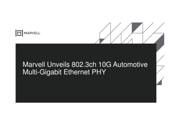
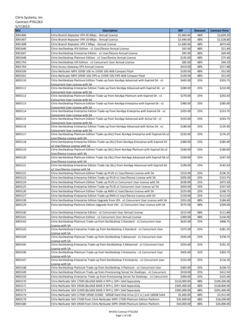
Chapter 1Overview10GBASE-R/KR is a 10 Gb/s serial interface. It is intended to provide the Physical CodingSublayer (PCS) and Physical Medium Attachment (PMA) functionality between the10 Gigabit Media Independent Interface (XGMII) interface on a Ten Gigabit Ethernet MediaAccess Controller (MAC) and a Ten Gigabit Ethernet network physical-side interface (PHY).The 10GBASE-KR core is distinguished from the 10GBASE-R core by the addition of a LinkTraining block as well as optional Auto-Negotiation (AN) and Forward Error Correction(FEC) features, to support a 10 Gb/s data stream across a backplane.10GBASE-RFor Zynq -7000, UltraScale , Virtex -7, and Kintex -7 devices, all of the PCS andmanagement blocks illustrated are implemented in logic, except for part of the Gearbox andSERDES. Figure 1-1 shows the architecture.X-Ref Target - Figure 1-1Fabric64b66bDecodeElasticBufferGTXE2/ icBlockSyncrxn,pBER etxn,pGearboxXGMII (SDR)MDIO Control StatusPCS/PMARegistersX12649-091115Figure 1-1:Implementation of the 10GBASE-R CoreThe major functional blocks include the following: XGMII interface, designed for simple attachment of 10 Gigabit Ethernet MAC Transmit path, including scrambler, 64b/66b encoder and Gearbox10G Ethernet PCS/PMA v6.0PG068 October 5, 2016www.xilinx.comSend Feedback5
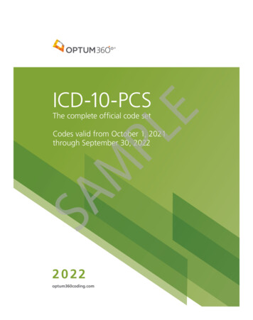
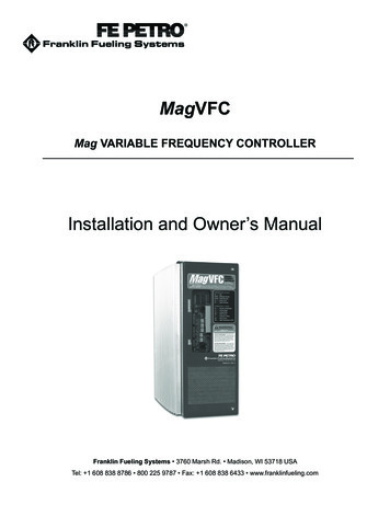
Chapter 1: Overview Receive path, including block synchronization, descrambler, decoder and BER (Bit ErrorRate) monitor Elastic buffer in the receive datapath.The elastic buffer is 32 words deep (1 word 64bits data 8 control). (For 32-bit10GBASE-R cores, the elastic buffer is twice the depth and half the width, but has thesame properties.) If the buffer empties, local fault codes are inserted instead of data.This allows you to collect up to 64 clock correction (CC) sequences before the bufferoverflows (and words are dropped). The buffer normally fills up to one half and thendeletes CC sequences when over half full, and inserts CC sequences when under one halffull. So from a half-full state, you can (conservatively) accept an extra 360 KB of data(that is, receiving at 200 ppm) without dropping any. From a half-full state you cancope with another 360 KB of data without inserting local faults (for –200 ppm). Test pattern generation and checking Serial interface to optics Management registers (PCS/PMA) with optional MDIO interface10GBASE-KRFigure 1-2 illustrates a block diagram of the 10GBASE-KR core implementation. The majorfunctional blocks include the following: XGMII interface, designed for simple attachment of 10 Gigabit Ethernet MAC Transmit path, including scrambler, 64b/66b encoder, FEC, AN and Training Receive path, including block synchronization, descrambler, decoder and BER (Bit ErrorRate) monitor, FEC, AN and Training Elastic buffer in the receive datapath.The elastic buffer is 32 words deep (1 word 64bits data 8 control). If the bufferempties, local fault codes are inserted instead of data. This allows you to collect up to 64clock correction (CC) sequences before the buffer overflows (and words are dropped).The buffer normally fills up to one half and then deletes CC sequences when over halffull, and inserts CC sequences when under one half full. So from a half-full state, you can(conservatively) accept an extra 360 KB of data (that is, receiving at 200 ppm) withoutdropping any. From a half-full state you can cope with another 360 KB of data withoutinserting local faults (for –200 ppm). Test pattern generation and checking Serial interface to backplane connector Management registers (PCS/PMA) with optional MDIO interface10G Ethernet PCS/PMA v6.0PG068 October 5, 2016www.xilinx.comSend Feedback6
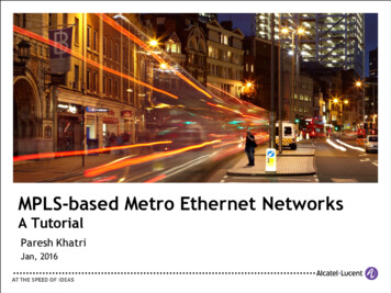
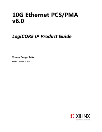
Chapter 1: OverviewX-Ref Target - Figure gicFECPCSANTRAINSERDEStxn,pXGMII(SDR)MDIOFigure 1-2:Control StatusPCS/PMARegistersImplementation of the BASE-KR CoreApplicationsFigure 1-3 shows a typical Ethernet system architecture and the core within it. The MAC andall the blocks to the right are defined in IEEE Std 802.3 [Ref 1].X-Ref Target - Figure 1-3 * (WKHUQHW 3&6 30 &RUHTCPIPFIFOI/FMACPCSPMAPMDX12648Figure 1-3:Typical Ethernet System ArchitectureFigure 1-4 shows the 10G Ethernet PCS/PMA core connected on one side to a 10G EthernetMAC and on the other to an optical module (BASE-R) or backplane (BASE-KR) using a serialinterface. The optional WAN Interface Sublayer (WIS) part of the 10GBASE-R standard is notimplemented in this core.The 10G Ethernet PCS/PMA core is designed to be attached to the Xilinx IP 10G EthernetMAC core over XGMII. More details are provided in Chapter 3, Designing with the Core.10G Ethernet PCS/PMA v6.0PG068 October 5, 2016www.xilinx.comSend Feedback7
Chapter 1: OverviewX-Ref Target - Figure 1-4FPGAUserLogic(10GEthernetMAC)XGMIIFigure 1-4:10GEthernetPCS/PMACoreSerialInterface10GBASE-R PHYor10GBASE-KR BackplaneCore Connected to MAC Core Using XGMII InterfaceUnsupported FeaturesThe following features are not supported in this release of the core.While the Training Protocol is supported natively by the core, no logic is provided thatcontrols the far-end transmitter adaptation based on analysis of the received signal quality.This is because extensive testing has shown that to be unnecessary.However, a training interface is provided on the core that allows access to all core registersand to the DRP port on the transceiver. You can employ this interface to implement yourown Training Algorithm for 10GBASE-KR, if required.Licensing and Ordering InformationLicense CheckersIf the IP requires a license key, the key must be verified. The Vivado design tools haveseveral license check points for gating licensed IP through the flow. If the license checksucceeds, the IP can continue generation. Otherwise, generation halts with error. Licensecheckpoints are enforced by the following tools: Vivado Synthesis Vivado Implementation write bitstream (Tcl command)10G Ethernet PCS/PMA v6.0PG068 October 5, 2016www.xilinx.comSend Feedback8
Chapter 1: OverviewIMPORTANT: IP license level is ignored at checkpoints. The test confirms a valid license exists. It doesnot check IP license level.License Type10G Ethernet PCS/PMA (10GBASE-R)This Xilinx LogiCORE IP module is provided at no additional cost with the Xilinx Vivado Design Suite under the terms of the Xilinx End User License. Information about this andother Xilinx LogiCORE IP modules is available at the Xilinx Intellectual Property page. Forinformation about pricing and availability of other Xilinx LogiCORE IP modules and tools,contact your local Xilinx sales representative.For more information, visit the 10 Gigabit Ethernet PCS/PMA (10GBASE-R) product webpage.10G Ethernet PCS/PMA with FEC/Auto-Negotiation (10GBASE-KR)This Xilinx LogiCORE IP module is provided under the terms of the Xilinx Core LicenseAgreement. The module is shipped as part of the Vivado Design Suite. For full access to allcore functionalities in simulation and in hardware, you must purchase a license for the core.Contact your local Xilinx sales representative for information about pricing and availability.For more information, visit the 10 Gigabit Ethernet PCS/PMA with FEC/Auto-Negotiation(10GBASE-KR) product web page. The 10G/25GBASE-KR/CR license key is bundled with thisproduct. For more information, visit the 10G/25G Ethernet Subsystem product web page.Information about this and other Xilinx LogiCORE IP modules is available at the XilinxIntellectual Property page. For information on pricing and availability of other XilinxLogiCORE IP modules and tools, contact your local Xilinx sales representative.10G Ethernet PCS/PMA v6.0PG068 October 5, 2016www.xilinx.comSend Feedback9
Chapter 2Product SpecificationStandardsThe 10GBASE-R/KR core is designed to the standard specified in clauses 45, 49, 72, 73 and74 of the 10 Gigabit Ethernet specification IEEE Std 802.3 [Ref 1].PerformanceTransceiver LatencySee the 7 Series Transceivers User Guide (UG476) [Ref 4], the UltraScale Architecture GTHTransceivers User Guide (UG576) [Ref 5], and the UltraScale Architecture GTY TransceiversUser Guide (UG578) [Ref 6] for information on the transceiver latency.64-Bit Data WidthLatencyThese measurements are for the core only; they do not include the latency through thetransceiver. The latency through the transceiver can be obtained from the relevant userguide.Transmit Path LatencyAs measured from the input port xgmii txd[63:0] of the transmitter side XGMII (untilthat data appears on gt txd[31:0] on the transceiver interface), the latency through the7 series core for the XGMII interface configuration in the transmit direction is 20 periods oftxoutclk. When the optional FEC functionality is included in the core and enabled, thisincreases to 26 periods of txoutclk.Measuring in the same way for an UltraScale device for 10GBASE-R, the transmit latencyis six periods of the 156.25 MHz transmit clock, which increases to 12 periods when FEC isincluded and enabled. The latency for UltraScale devices for 10GBASE-KR is 20 periods of10G Ethernet PCS/PMA v6.0PG068 October 5, 2016www.xilinx.comSend Feedback10
Chapter 2: Product Specificationtxoutclk. When the optional FEC functionality is included in the core and enabled, thisincreases to 26 periods of txoutclk.Receive Path LatencyLatency in the receive direction is variable and depends mainly on the fill level of the receiveelastic buffer.Measured from the input into the core on gt rxd[31:0] until the data appears onxgmii rxd[63:0] of the receiver side XGMII interface, the latency through the 7 seriescore in the receive direction is nominally equal to 1831 UI, or 27.75 cycles of coreclk,increasing to 2723 UI, or 41.26 cycles of coreclk when the elastic buffer is at its fullestpossible level. The exact latency depends on sync bit alignment position and datapositioning within the transceiver 4-byte interface. For UltraScale devices in 10GBASE-Rconfiguration, excluding the elastic buffer, the latency through the core in the receivedirection is nominally equal to seven cycles of the 156.25 MHz receive clock. The latencythrough the elastic buffer is the same as calculated for 7 series devices (the number ofcycles is for the 156.25 MHz receive clock). For UltraScale devices in 10GBASE-KRconfiguration the latency is same as calculated for 7 series cores.When the optional FEC functionality is included in the core the UltraScale core has a singleextra cycle of the 156.25 MHz receive clock and this increases for all devices by 70 cycles ofrxrecclk out when FEC is enabled and if error reporting to the PCS layer is enabled,there is an extra 66 cycles of rxrecclk out latency.32-Bit Data WidthLatencyThese measurements are for the core only; they do not include the latency through thetransceiver. The latency through the transceiver can be obtained from the relevant userguide. There is a margin of error of 33 UI (a single 32-bit XGMII word) with these numbers.Transmit Path LatencyAs measured from the input port xgmii txd[31:0] of the transmitter side XGMII (untilthat data appears on gt txd[31:0] on the transceiver interface), the latency through thecore for the XGMII interface configuration in the transmit direction for 7 series devices is 14periods of txoutclk. For UltraScale devices this is eight periods of the 312.5 MHz transmitclock.Receive Path LatencyLatency in the Receive direction is variable and depends mainly on the fill level of thereceive elastic buffer.10G Ethernet PCS/PMA v6.0PG068 October 5, 2016www.xilinx.comSend Feedback11
Chapter 2: Product SpecificationMeasured from the input into the core on gt rxd[31:0] until the data appears onxgmii rxd[31:0] of the receiver side XGMII interface, the latency through the core in thereceive direction for 7 series devices is nominally equal to 1472 UI, or 44.6 cycles ofcoreclk, increasing to 72 cycles of coreclk when the elastic buffer is at its fullestpossible level. The exact latency depends on sync bit alignment position and datapositioning within the transceiver 4-byte interface. For UltraScale devices, excluding theelastic buffer, the latency is eight cycles of the 312.5 MHz receive clock.Resource UtilizationFor details about resource utilization, visit Performance and Resource Utilization.Port DescriptionsThis section provides information about the ports for the XGMII interface and for the serialdata interface. Additionally, information is provided about the ports for the managementinterface (MDIO) and its alternative, the vector-based configuration and status signals.Information is also provided about the clock and reset signals, the DRP training interfaceports, the transceiver debug ports and miscellaneous core signals.XGMII Interface SignalsFor 10GBASE-R, the core provides the option of a 64-bit or a 32-bit XGMII data width (theselected data width also applies internally to the core). For the 10GBASE-KR option, only the64-bit option is available.64-Bit XGMIIWhen the 64-bit datapath is selected, the MAC (or client) side of the core has a 64-bitdatapath plus eight control bits implementing an XGMII interface. Table 2-1 defines thesignals, which are all synchronous to a 156.25 MHz clock source; the relevant clock port isdependent upon the family and core permutation. It is designed to be connected to eitheruser logic within the FPGA or, by using SelectIO technology Double Data Rate (DDR)registers in your own top-level design, to provide an external 32-bit DDR XGMII, defined inclause 46 of IEEE Std 802.3. TX clock source and RX clock source are defined in Table 3-1.Table 2-1:MAC-Side Interface PortsSignal NameDirectionClock Domainxgmii txd[63:0]InTX clock source64-bit transmit data wordxgmii txc[7:0]InTX clock source8-bit transmit control word10G Ethernet PCS/PMA v6.0PG068 October 5, 2016www.xilinx.comDescriptionSend Feedback12
Chapter 2: Product SpecificationTable 2-1:MAC-Side Interface PortsSignal NameDirectionClock DomainDescriptionxgmii rxd[63:0]OutRX clock source64-bit receive data wordxgmii rxc[7:0]OutRX clock source8-bit receive control word32-bit XGMIIWhen the 32-bit datapath is selected, the MAC (or client) side of the core has a 32-bitdatapath plus four control bits implementing an XGMII interface. Table 2-2 defines thesignals, which are all synchronous to a 312.5 MHz clock source; the relevant clock port isdependent upon the family and core permutation. It is designed to be connected to userlogic within the FPGA. TX clock source and RX clock source are defined in Table 3-1.Table 2-2:MAC-Side Interface PortsSignal NameDirectionClock DomainDescriptionxgmii txd[31:0]InTX clock source32-bit transmit data wordxgmii txc[3:0]InTX clock source4-bit transmit control wordxgmii rxd[31:0]OutRX clock source32-bit receive data wordxgmii rxc[3:0]OutRX clock source4-bit receive control wordSerial Data PortsThe serial data ports should be connected to the PMD which is either an optical module ora backplane.Table 2-3:Serial Data PortsSignal NameDirectiontxn, txpOutrxn, rxpInDescriptionSerial data to optics/backplaneSerial data from optics/backplaneOptical Module Interface PortsThe status and control interface to an attached optical module is a simple pin-to-pininterface on those pins that need to be connected. The signals are described in Table 2-4.See Chapter 3, Designing with the Core for details on connecting an optical module to the10GBASE-R core. For 10GBASE-KR, it is recommended to tie signal detect to 1,tx fault to 0, and leave tx disable unconnected.10G Ethernet PCS/PMA v6.0PG068 October 5, 2016www.xilinx.comSend Feedback13
Chapter 2: Product SpecificationTable 2-4:Optical Module Interface PortsSignal NameDirectionDescriptionsignal detectInStatus signal from attached optical module. (1)tx faultInStatus signal from attached optical module.(2)(3)tx disableOutControl signal to attached optical moduleNotes:1. When an optical module is present, the logical NOR of MODDEF0 and LOS (Loss of Signal) outputs should be usedto create the signal detect input to the core.2. This signal is not connected inside this version of the core. You should handle these inputs and reset your designas required.3. Connect to SFP tx fault signal, or XFP MOD NR signal, depending on which is present.Management Interface (MDIO) PortsThe optional MDIO interface is a simple low-speed two-wire interface for management ofthe 10G Ethernet PCS/PMA core, consisting of a clock signal and a bidirectional data signal.The interface is defined in clause 45 of the IEEE 802.3-2012 standard.In this core, the MDIO interface is an optional block. If implemented, the bidirectional datasignal MDIO is implemented as three unidirectional signals. These can be used to drive a3-state buffer either in the FPGA IOB or in a separate device.Where a single point-to-point connection to a MAC is required, connect mdio in on the10G Ethernet PCS/PMA core to mdio out on the MAC and vice versa, leaving themdio tri output unconnected. The mdio tri signal is not required for a point-to-pointconnection.Table 2-5:MDIO Management Interface PortsSignal NameDirectionDescriptionmdcInManagement clockmdio inInMDIO Inputmdio outOutmdio triOutprtad[4:0]InMDIO OutputMDIO 3-state control.1 disconnects the output driver from the MDIO bus.MDIO port address. When multiple MDIO-managed ports appear on thesame bus, this input can be used to set the address of each port.Clock and Reset PortsThe clock and reset ports are described in this section for both Shared Logic options.10G Ethernet PCS/PMA v6.0PG068 October 5, 2016www.xilinx.comSend Feedback14
Chapter 2: Product SpecificationShared Logic Included in Example DesignIf Include Shared Logic in example design is selected during the core customization,circuits for clock and reset management are included in the top-level example designsources. These can include clock generators, reset synchronizers, or other circuits that canbe useful in your particular application. Table 2-6 shows the ports on the core that areassociated with clocks and resets.Table 2-6:Clock and Reset Ports—Shared Logic in Example DesignSignal NameDirectionDescriptionInThis clock is used to clock the TX datapath and management logic in7 series devices and for 10GBASE-KR in UltraScale devices. InUltraScale devices for 10GBASE-R this clock is used only as a freerunning clock source for reset logic associated with the transceiver.txusrclk, txusrclk2InConnected to the TXUSRCLK and TXUSRCLK2 input ports of thetransceiver, these clocks are derived from the TXOUTCLK from thetransceiver. In UltraScale devices for 10GBASE-R txusrclk2 is used toclock the transmit datapath and management logic.dclk(1)InManagement/DRP clock: this clock can be any rate that is valid forthe applicable transceiver DRPCLK.aresetInAsynchronous (master) reset(2)coreclktxoutclkOutTXOUTCLK from the transceiver used in the shared clock generationlogicrxrecclk outOutRXOUTCLK from the transceiverareset coreclkInSynchronous reset in the coreclk domaingttxresetInTransceiver TX reset signal in the coreclk domaingtrxresetInTransceiver RX reset signal in the coreclk domainqplllockInTransceiver QPLL Lock signal for 7 series devicesqplloutclkInTransceiver QPLL clock for 7 series devicesqplloutrefclkInTransceiver QPLL refclk for 7 series devicesqpll0lockInTransceiver QPLL lock signal for UltraScale devicesqpll0outclkInTransceiver QPLL clock for UltraScale devicesqpll0outrefclkInTransceiver QPLL refclk for UltraScale devicesreset counter doneInIndication that 500 ns have passed after configuration was completetx resetdoneOutTransceiver TX reset-donerx resetdoneOutTransceiver RX reset-donereset tx bufg gtOutControl from core to the BUFG GT in the shared logic. Only for64-bit datapath cores on UltraScale devices10G Ethernet PCS/PMA v6.0PG068 October 5, 2016www.xilinx.comSend Feedback15
Chapter 2: Product SpecificationTable 2-6:Clock and Reset Ports—Shared Logic in Example Design (Cont’d)Signal Nameqpll0resetDirectionOutDescriptionFor UltraScale devices, a reset signal from the core to the QPLLlocated in the shared logic.Notes:1. For UltraScale devices the DCLK must be free-running and the frequency must be kept less than or equal to themaximum DRPCLK frequency specified for the transceiver type or the TXUSRCLK2 frequency, which is 156.25 MHzfor 64-bit datapaths.2. This reset also resets all management registers.Shared Logic Included in CoreIf Include Shared Logic in core is selected during core customization, most of the clockingand reset blocks are included within the core. Table 2-7 shows the ports on the core that areassociated with these clocks and resets, which can be reused by other user logic or IP cores.Table 2-7:Clock and Reset Ports—Shared Logic in CoreSignal NameDirectionDescriptionrefclk p, refclk nInDifferential clock input (for transceiver)dclk(1)InManagement/DRP clock: this clock can be any rate that is valid forthe applicable transceiver drpclkresetInAsynchronous master reset (2)OutCombined transceiver reset-done indication (in the coreclk outdomain)coreclk outOutThis is used to clock the TX datapath and management logic in7 series devices and for 10GBASE-KR in UltraScale devices. InUltraScale devices for 10GBASE-R this clock is used only as a freerunning clock source for reset logic associated with thetransceiver.qplllock outOutLock indication from QPLL block in core for 7 series devicesqplloutclk outOutQPLL output clock from QPLL block in core for 7 series devicesqplloutrefclk outOutQPLL output reference clock from QPLL block in core for 7 seriesdevicesqpll0lock outOutLock indication from QPLL block in core for UltraScale architectureqpll0outclk outOutQPLL output clock from QPLL in core for UltraScale architectureqpll0outrefclk outOutQPLL output reference clk from QPLL in core for UltraScalearchitecturetxusrclk outOuttxusrclk from shared logic block in coretxusrclk2 outOuttxusrclk2 from shared logic bl
contact your local Xilinx sales representative. For more information, visit the 10 Gigabit Ethernet PCS/PMA (10GBASE-R) product web page. 10G Ethernet PCS/PMA with FEC/Auto-Negotiation (10GBASE-KR) This Xilinx LogiCORE IP module is provided under the terms of the Xilinx Core License Agreement. The module is shipped as part of the Vivado Design .