Transcription
561Infrared ThermometerUsers ManualPN 2562924February 2006 Rev. 3, 4/08 2006-2008 Fluke Corporation, All rights reserved. Printed in China. Specifications are subject to changewithout notice. All product names are trademarks of their respective companies.
LIMITED WARRANTY AND LIMITATION OF LIABILITYThis Fluke product will be free from defects in material and workmanshipfor two years from the date of purchase. This warranty does not coverfuses, disposable batteries, or damage from accident, neglect, misuse,alteration, contamination, or abnormal conditions of operation or handling.Resellers are not authorized to extend any other warranty on Fluke’s behalf. To obtain service during the warranty period, contact your nearestFluke authorized service center to obtain return authorization information,then send the product to that Service Center with a description of theproblem.THIS WARRANTY IS YOUR ONLY REMEDY. NO OTHER WARRANTIES, SUCH AS FITNESS FOR A PARTICULAR PURPOSE, ARE EXPRESSED OR IMPLIED. FLUKE IS NOT LIABLE FOR ANY SPECIAL,INDIRECT, INCIDENTAL OR CONSEQUENTIAL DAMAGES ORLOSSES, ARISING FROM ANY CAUSE OR THEORY. Since some statesor countries do not allow the exclusion or limitation of an implied warrantyor of incidental or consequential damages, this limitation of liability maynot apply to you.Fluke CorporationP.O. Box 9090Everett, WA 98206-9090U.S.A.11/99Fluke Europe B.V.P.O. Box 11865602 BD EindhovenThe Netherlands
Table of ContentsTitlePageIntroduction .Contacting Fluke .Safety Information .Features .Display .Buttons and Connector .How the Thermometer Works .Operating the Thermometer .Locating a Hot or Cold Spot .Distance and Spot Size .Field of View .Emissivity .Switching Between C and F.Using the Contact Temperature Probe .HOLD .Maintenance .Changing the Battery.Cleaning the Lens.Cleaning the Housing .Troubleshooting .CE Certification .Specifications .i112345666677891010101010111111
561Users Manualii
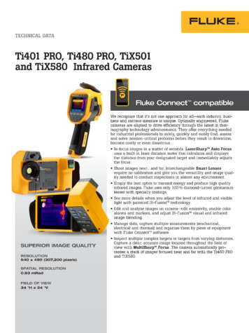
561Infrared ThermometerIntroductionThe Fluke 561 Infrared Thermometer (hereafter, the Thermometer) can determine the surfacetemperature by measuring the amount of infrared energy radiated by the target’s surface or bycontact using a thermocouple probe. The Thermometer was designed specifically for use inheating, ventilating, and air conditioning (HVAC) applications. This manual covers all versionsof the the Fluke 561. Note that the Japanese models indicate Celsius only.Contacting FlukeTo contact Fluke, call one of the following telephone numbers:USA: 1-888-44-FLUKE (1-888-443-5853)Canada: 1-800-36-FLUKE (1-800-363-5853)Europe: 31 40 267 5200Japan: 81-3-3434-0181Singapore: 65-738-5655Anywhere in the world: 1-425-446-5500For USA Service: 1-888-99-FLUKE (1-888-993-5853)Or, visit Fluke's Web site at www.fluke.com.To register your product, visit http://register.fluke.com.1
561Users ManualSafety InformationXWWarningA Warning identifies conditions and actions that pose hazards to the user. Toavoid electrical shock or personal injury, follow these guidelines: * Do not point laser directly at eye or indirectly off reflective surfaces. Before using the Thermometer inspect the case. Do not use the Thermometerif it appears damaged. Look for cracks or missing plastic. Replace the batteries as soon as the battery indicator (B) appears. Do not use the Thermometer if it operates abnormally. Protection may beimpaired. When in doubt, have the Thermometer serviced. Do not operate the Thermometer around explosive gas, vapor, or dust. Do not connect the optional external probe to live electrical circuits. To avoid a burn hazard, remember that highly reflective objects will oftenresult in lower than actual temperature measurements. If the Thermometer is used in a manner not specified by the manufacturer, theprotection provided by the Thermometer may be impaired.WCautionTo avoid damaging the thermometer or the equipment under test protect themfrom the following: EMF (electro-magnetic fields) from arc welders, induction heaters, etc. Static electricity. Thermal shock (caused by large or abrupt ambient temperature changesallow 30 minutes for the Thermometer to stabilize before use). Do not leave the Thermometer on or near objects of high temperature.Table 1 and Figure 1 show various symbols and safety markings that are on the Thermometerand in this manual.Table 1. SymbolsSymbolWX*PConforms to requirements of European Union and European FreeTrade Association (EFTA). Do not dispose of this product as unsorted municipal waste. Go toFluke’s web site for recycling information.B„2ExplanationRisk of danger. Important information. See Manual.Hazardous voltage. Risk of electrical shock.Warning. Laser.BatteryChina metrology certification mark for measuring instrumentsmanufactured in the Peoples Republic of China (PRC).
Infrared ThermometerFeatures- LASER RADIATIONAVOID EXPOSURETHIS APERTUREIS EMITTED FROMCAUTIONLASER RADIATION- DO NOT STAREINTO BEAM630 - 670nmWAVELENGTHOUTPUT 1mW PRODUCTCLASS 2 (II) LASERFDA 21CFRCOMPLIES WITH1040.10 AND 1040.11IEC 60825COMPLIES WITHAVOID EXPOSURE - LASER RADIATIONIS EMITTED FROM THIS APERTURECAUTIONLASER RADIATION - DO NOT STARE INTO BEAMOUTPUT 1mW WAVELENGTH 630 - 670nmCLASS 2 (II) LASER PRODUCTCOMPLIES WITH FDA 21CFR1040.10 AND 1040.11COMPLIES WITH IEC 60825efh010f.epsFigure 1. Symbols and Safety MarkingsFeaturesThe Thermometer includes: Single-spot Laser Sighting Backlit Display Hard Case Current Temperature Plus MIN, MAX, DIF Temperature Displays Easy Emissivity Selector Type-K Thermocouple Two AA BatteriesThermometer features are shown in Figure 2.3
561Users ManualLaserDisplayTriggerAABatteries(2)Function Buttons( )BatteryCoverefh007f.epsFigure 2. Infrared ThermometerDisplayThe primary temperature display reports the current or last IR temperature read until the 7second hold time elapses.The secondary temperature display reports current thermocouple temperature when a type-Kthermocouple is attached. When a thermocouple is not connected, the small temperaturedisplay reports a choice of maximum, minimum, or difference between maximum and minimumtemperature.You can toggle through the minimum, maximum, and difference IR temperatures anytime thedisplay is on. The MIN, MAX, and DIF temperatures are constantly calculated and updatedwhen the trigger is pressed. After the trigger is released, the MIN, MAX, DIF temperatures areheld for 7 seconds.NoteWhen the battery is low, B appears on the display.The last selection (MIN/MAX/DIF) is maintained on the secondary display even after theThermometer has been turned off, providing the batteries have not failed.4
Buttons and Connector21384576efh01f.epsABCDEFGHLaser “On” symbolSCAN or HOLD C/ F symbol (Celsius/Fahrenheit)Primary temperature displaySecondary temperature displayEmissivity LO, MED, HITemperature values for the MIN, MAX, DIF, KTC.KTC indicates the thermocouple temperature.Low Battery symbol. Appears when the battery charge is 25 %.Figure 3. Thermometer DisplayButtons and ConnectorButton/ConnectorCDescriptionCPressand then pressMAX, and DIF options.A to toggle between the MIN,AAThebutton is used to show the MIN, MAX, and DIFfunctions in the secondary display, whichever was pressedmost recently.DSelects the emissivity setting. You can toggle between LO(0.3), MED (0.7), or HI (0.95) using .AK-type thermocouple probe used to make contacttemperature measurement.5
561Users ManualHow the Thermometer WorksInfrared thermometers measure the surface temperature of an opaque object. TheThermometer’s optics sense infrared energy, which is collected and focused onto a detector.The Thermometer’s electronics then translate the information into a displayed temperaturereading which appears on the display. The laser is used for aiming purposes only.Operating the ThermometerThe Thermometer turns on when you press the trigger. The Thermometer turns off when noactivity is detected for 7 seconds.To measure temperature, aim the Thermometer at the target, pull and hold the trigger. Releasethe trigger to hold a temperature reading.Be sure to consider distance-to-spot size ratio and field of view. The laser is used for aimingonly.Locating a Hot or Cold SpotTo find a hot or cold spot, aim the Thermometer outside the target area. Then, slowly scanacross the area with an up and down motion until you locate the hot or cold spot. See Figure 4.efh014f.epsFigure 4. Locating a Hot or Cold SpotDistance and Spot SizeAs the distance (D) from the target being measured increases, the spot size (S) of the areameasured by the unit becomes larger. The spot sizes indicates 90 % encircled energy. Themaximum D:S is obtained when the Thermometer is 900 mm (36 in) from the target resulting ina spot size of 75 mm (3 in). See Figure 5.6
Operating the Thermometer75 mm @900 mm132 mm @1500 mmS38 mm @300 mm1.5 " @12 "3"@36 "5.3 " @60 "DD:S 12:1efh005f.epsFigure 5. Distance and Spot SizeField of ViewMake sure that the target is larger than the spot size. The smaller the target, the closer youshould be to it. See Figure 6.YesNoefh004f.epsFigure 6. Field of ViewEmissivityEmissivity describes the energy-emitting characteristics of materials. Most organic materialsand painted or oxidized surfaces have an emissivity of about 0.95.If possible, to compensate for inaccurate readings that may result from measuring shiny metalsurfaces, cover the surface to be measured with masking tape or flat black paint( 148 C/300 F) and use the high emissivity setting. Allow time for the tape or paint to reachthe same temperature as the surface beneath it. Measure the temperature of the tape orpainted surface.If you cannot paint or use tape, then you can improve the accuracy of your measurements withthe emissivity selector. Even with the emissivity selector, it can be difficult to get a completelyaccurate infrared measurement of a target with a shiny or metallic surface. Experimentation,using the probe to determine benchmark temperatures, and experience will help you choose thebest setting for specific measurements.The Thermometer has three emissivity settings: low (0.3), medium (0.7), and high (0.95). Referto Table 2. The reference to emissivity settings in the table are suggestions for typicalsituations. Your particular situation may differ.7
561Users ManualTable 2. Surface urfaceSwitch SettingIron, CastLowAlloy A3003OxidizedLowMoltenLowLowRoughenedLowIron, xidizedMediumElectrical TerminalBlocksMediumHaynesHigh, MediumUnoxidizedOxidizedAlloySwitch SettingHighRoughLowOxidizedLow, MediumMolybdenumOxidizedLow, edHigh, izedHigh, und SheetMediumPolished SheetLowZincOxidizedLowSwitching Between C and FOpen the battery compartment and locate the switch positioned between the left side of thebattery near the Thermometer wall. To toggle between C and F, use a small screwdriver orpaper clip to move the switch to the desired position. See Figure 7.8
Operating the ThermometerSwitchFigure 7. Switching Between C and Fefh012f.epsUsing the Contact Temperature ProbeXW WarningTo avoid electrical shock or personal injury, do not connect the optional externalprobe to live electrical circuits.Connect the probe to the input on the top of the Thermometer. The probe temperature and KTCappears in the secondary display. The live infrared temperature continues to show in theprimary display. Connect the temperature probe as shown in Figure 8.NoteWith the probe inserted, the Thermometer stays on for 10 minutes (with laser off)after the trigger is released.efh009f.epsFigure 8. Connecting the Temperature Probe9
561Users ManualTable 3 lists recommended Fluke temperature probes for use with the Thermometer:Table 3. Recommended Temperature ProbesProbeUsage80PK-25The piercing probe is the most versatile option. Good for checking airtemperature in ducts, surface temperature under carpets/pads, liquids,thermometer wells, vent temperatures, and for penetrating pipe insulation.80PK-1The general purpose bead probe is an alternative, for quick, accurate surfacetemperatures and air temperatures within ducts, vent temperatures.80PK-8Pipe clamp probes (2) are essential for tracking continuously changingtemperature differentials on hydronic tubing and pipe loops, and good forquick, accurate refrigerant temperatures.80PK-26The tapered probe is a good general-purpose gas and surface probe, with agood length and low mass tip casing for faster reaction to surface and airtemperatures.80PK-9The insulation piercing probe provides a sharp tip to pierce pipe insulationand flat probe tip for good surface thermal contact, air temperatures withinducts, and vent temperatures.80PK-11The Velcro pipe probe is a convenient way to attach a thermocouple to apipe while keeping hands free.HOLDThe display will remain activated for 7 seconds after the trigger is released. HOLD appears inthe upper middle of the display. When the trigger is pulled again, the Thermometer will beginmeasuring in the last function selected.MaintenanceChanging the BatteryTo install or change the two AA batteries, open the battery compartment and insert the batteriesas shown in Figure 2.Cleaning the LensBlow off loose particles using clean compressed air. Carefully wipe the surface with a moistcotton swab. The swab may be moistened with water.Cleaning the HousingUse soap and water on a damp sponge or soft cloth.WCautionTo avoid damaging the Thermometer, do NOT submerge it in water.10
TroubleshootingTroubleshootingSymptom--- (on display)BBlank displayLaser does notworkProblemTarget temperature is over orunder rangeLow batteryPossible dead battery1. Low or dead battery2. Ambient temperature above40 C (104 F)ActionSelect target withinspecificationsReplace batteryCheck and/or replace battery1. Replace battery2. Use in area with lowerambient temperatureCE CertificationThe Thermometer conforms to the following standards: EN61326-1 EMC Standard EN61010-1 Safety Standard EN60825-1 Laser StandardCertification testing was conducted using a frequency range of 80 to 1000 MHz with theinstrument in three orientations.SpecificationsInfraredMeasurement Range . -40 C to 550 C (-40 F to 1022 F)Spectral Range. 8 to 14 micronsAccuracy . 1 % or 1 C (2 F); 0 C (32 F), 1 C (2 F) 0.1 /1 (Assumesambient operating temperature of 23to 25 C (73 to 77 F))Repeatability. 0.5 % of reading or 1 C (2 F)Display Resolution. 0.1 C (0.1 F)Secondary Display Information. Maximum, Minimum, Differential,KTCResponse Time (95 %). 500 msDistance to Spot (D:S). 12:1Emissivity Adjustment. Three settings: low (0.3), medium(0.7), high (0.95)Contact Probe InputInput Temperature Range . -40 C to 550 C (-40 F to 1022 F)Input Accuracy.Input accuracy 1.1 C ( 2 F)Display Resolution. 1 C (1 F)LaserSighting . Single point laserPower . Class 2 (II) operation; Output 1 mW,wavelength 630 to 670 nm11
561Users ManualWrap Thermocouple Probe (model-specific)Type.Type K with miniconnector andVelcro strap, ASTM E230-03Standard ToleranceMeasurement Range .0 C to 100 C (32 F to 212 F)Accuracy . 2.2 C (4.0 F)Total Length.505 mm (20 in) cable terminated witha Type K thermocouple inside a495 mm (19.5 in) nylon Velcro cuffBead Thermocouple Probe (model-specific)Type.Type K with miniconnectorMeasurement Range . -40 C to 260 C (-40 F to 500 F)Accuracy . 1.1 C (2.0 F) from 0 C to 260 C(32 F to 500 F). Typically within1.1 C(2.0 F) from -40 C to 0 C(-40 F to 32 F)Cable Length .1 m (40 in) terminated with Type Kthermocouple beadsElectricalPower Supply.2 AA Batteries (alkaline or NiCD)Power Consumption.At least 12 hours battery lifePhysicalWeight.0.322 kg (0.7099 lb)Size.17.69 cm (6.965 in) x 16.36 cm(6.441 in) x 5.18 cm (2.039 in)EnvironmentalOperating Temperature Range .0 C to 50 C (32 F to 120 F)Relative Humidity .0 to 90 %, noncondensing up to30 C (86 F)Storage Temperature .-20 C to 65 C (-4 F to 150 F)Optional Accessories .Soft Case12
AVOID EXPOSURE - LASER RADIATION IS EMITTED FROM THIS APERTURE CAUTION LASER RADIATION - DO NOT STARE INTO BEAM OUTPUT 1mW WAVELENGTH 630 - 670nm CLASS 2 (II) LASER PRODUCT COMPLIES WITH FDA 21CFR 1040.10 AND 1040.11 COMPLIES WITH IEC 60825 efh010f.eps Figure 1. Symbols and Safety Markings Features The Thermometer includes: