Transcription
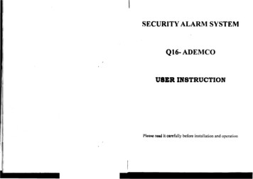
Available with Navigator, Saturn orKPX keypad optionsD8xD / D16xD Alarm Control PanelDeluxe edition with expanded AUX outputs, Voice alarms,Voice prompts, enhanced modem, Real time clock.816AUX8 or 16Hardwired orWireless zonesAuto-TimeAutomationUp to 8 AUXOutputsVariousKeypadOptionsEasyProgrammingvia KeypadFastProgrammingvia PCFreeNessCommsInstaller SoftwareOn-SiteProgrammingvia PD ToolOperation bySmartphone /InternetOperation byTelephoneBack To Baseor Voice DiallerMonitoringAdjustableVibration Inputson all ZonesInstallation & Programming ManualVoice Alarms& C-BUSCompatibleusing NessMiniCentralAreaPartitioning17VAC & 20VDCD8x/D16x DeluxeVersion v8.xDual VoltageDocument 890-017Rev 2.3
Innovative Electronic Solutionswww.ness.com.auNational Customer Service CentrePh: 1300 551 991customerservice@ness.com.auD8x/D16x DELUXEInstallATION & PROGRAMMING ManualDocument Part No: 890-017Rev 2.3 August 2019For use with Ness D8x/D16x DELUXE control panels V8.0 and later.This manual can also be used for previous versions of D8x/D16x panelshowever some of the programming options covered are available only inV8.0 and later.Refer to installation manual 890-007 for D8x/D16x V7.8 and earlier.Warnings & NoticesNess Corporation manufacturing processes are accredited to ISO9001 quality standards and all possible care and diligence has beenapplied during manufacture to ensure the reliable operation of this product. However there are various external factors that may impedeor restrict the operation of this product in accordance with the product’s specification.These factors include, but are not limited to:1. Erratic or reduced radio range (if radio accessories are installed). Ness radio products are sophisticated low power devices, howeverthe presence of in-band radio signals, high power transmissions or interference caused by electrical appliances such as MainsInverters, Wireless Routers, Cordless Phones, Computers, TVs and other electronic devices may reduce radio range performance.While such occurrences are unusual, they are possible. In this case it may be necessary to either increase the physical separationbetween the Ness receiver and other devices or if possible change the radio frequency or channel of the other devices.2. Unauthorised tampering, physical damage, electrical interruptions such as mains failure, electrical spikes or lightning.3. Solar power inverters are a known source of electrical interference. Please ensure that this product and all associated cabling isinstalled at least 3 metres away from a solar power inverter and its cabling.WARNING: Installation and maintenance to be performed only by qualified service personnel.CAUTION: Risk of explosion if battery is replaced by an incorrect type. Dispose of used batteries in accordance with local regulations.ADSL NOTICE: ADSL broadband data can interfere with the operation of your alarm dialler. It is recommended that a quality ADSL filterbe installed as per the filter manufacturer's guidelines in premises with an alarm dialler installed.All rights reserved. No part of this publication may be reproduced, transmitted or stored in a retrieval system in any form or by anymeans, electronic, mechanical, photocopying, recording, or otherwise, without the prior written permission of Ness.Ness reserves the right to make changes to features and specifications at any time without prior notification in the interest of ongoingproduct development and improvement. 2019 Ness Corporation Pty Ltd ABN 28 069 984 372
Need to get running fast?See the Quick Start Programming GuideProduct features. 4NessComms Features. 5Installation notes. 6Inputs and outputs. 7Connection diagram. 8–9Keypad. 10OperationOperation Summary . 11How to programQuick start Programming. 12How to enter Program Mode. 13How to program using NessPD. 13Special FunctionsSend test report. 12Siren test. 12Panel reset. 12Display software version. 12General OptionsUser Codes. 14, 15Timers. 16Vibration Sensitivity. 17Zone Assignment. 18, 19Definitions. Day Zones, Temp Day Zones, Home. 20Zone To Output Mapping. 22–23Various Options. 24–25Tamper/Keypad Panic Output Mapping. 26System Operation Shortcuts. 27Home mode output mapping. 28Day mode output mapping. 28Miscellaneous Options. 29–30Zone Supervision options. 31–33Misc. options . 35–37Dialler OptionsTelephone Numbers. 38–39Account Numbers. 38Report zone alarms. 40Report zone restorals. 40Report multiple zone alarms. 40Account No.2 zones. 40Report Miscellaneous alarms. 41Report Miscellaneous Restorals. 41Test Call options. 42Dialler format options. 43–44Contact ID Reporting Codes . 43Dialling options. 45Area1, Area2 open/close reports. 46Siren Chirp, Flash options. 46Other reports. 47Enable Test Calls. 48Mains Report Delay. 48Listen-in to dialler. 48Swinger Shutdown. 49Page12CONTENTSLine Fault Monitor. 49Remote access options. 50–51Required Rings. 52No Memory Warning zones. 52Factory DefaultsClear Radio Devices. 53Clear Memory. 53Clear Panel Options. 53Clear User Codes. 53Output Expander options. 54–56Aux outputsAux1 output options. 58-59Aux2 output options. 60-61Aux3 output options. 62-63Aux4 output options. 64-65Aux5–8 output options. 66-67Alarm/Fire/Chirp Siren Volume. 67Enable/Disable hardwire zones. 68KPX Keypad options. 68End Of Line Resistor options. 68AutoTime OptionsAutoTime description and examples. 69RealTime Clock programming. 70AutoTime programming. 70-71Radio OptionsSignal strength test. 72Ness Radio Interface. 72Radio Device Programming . 73Radio Key Programming. 74Serial Output options. 75Access Control OptionsProgramming access cards. 76Access Control options. 77–81Weigand Reader wiring diagram. 82Remote OperationMonitoring operation. 83System Name programming. 84Voice Message Library. 84Remote operation by telephone . 85Programming Options Summary. 86–91D8x/D16x Product List. 92Specifications and approvals. 92Release Notes. 93Installation Record. 95
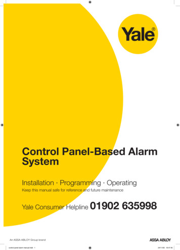
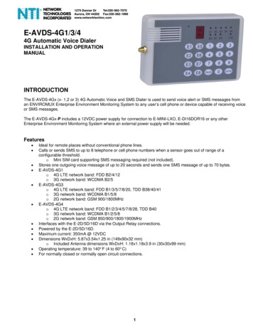
What's New in D8x/D16x Deluxe (v8) New PCB layout Added modem chip, use any modem in 300baud mode Voice alarms and voice prompts using a preset voice message library Real time clock onboard New connector for the Serial port, now 4 pin New connector for the Listen-in header Dual 17VAC/20VDC power input Tamper/Prog link moved to corner of pcb for better accessibilityOptional ProductNess iCommsNess aCommsNess iComms and aComms appsfor mobile control of your D8x/ 16xcontrol panel from home, office,anywhere in the world using youriPhone/iPad or Android device. Arm, Disarm View zone status Emergency alarms Control the panel outputs(D8x/D16x V7.8 )Requirements:D8x/D16x V5.6 or later (V7.8 or laterto operate panel outputs).Optional K-6002D Ethernet kit(includes 101-244 Ethernet adapter &450-246 RS232 cable).iPhone/iPad/Smartphone notincluded.iComms and aComms are third partyapps which are endorsed by Nesswithout tech support.Emergency alarms must be enabledin the control panel to be available iniComms and aComms.D8x/D16x All Features 8 or 16 alarm zones. Supports up to 3 mixed keypads (Navigator/Saturn/LCD) or 4 Navigator keypads 56 user codes can be programmed to operate by keypad PIN, radio key or accesscard. Optional Ness Radio Interface for fully integrated wireless security. Programmable Two Area partitioning can split the panel into two independentareas plus a common area. Real Time Clock with AutoTime features - auto arm/disarm, auto aux outputs,time based user control. 3 Door Access Controller onboard with support for Weigand prox or fingerprintreaders. Supports control via internet using Ness iComms/aComms iPhone/iPad andAndroid apps and optional ethernet adapter. Voice alarm reports & Voice prompts for remote telephone operation. Home Mode allows partial arming, (eg, perimeter security overnight). Day Mode feature allows daytime monitoring of fire doors, coolrooms etc. Temporary Day Zone feature allows easy enabling/disabling of Day Mode. Keypad Panic and Duress feature. Two button arming feature. Fire Alarm feature with different siren tones. Highly flexible zone to output mapping. Onboard Vibration Sensor Analyser with programmable sensitivity. Use withNessensor vibration sensors. Multiple programmable EOL resistor values from 0k to 22k (2k2 resistorssupplied). Siren chirp and strobe flash on arming with radio key. Quiet chirps option on arm/disarm by radio key. True Dynamic Battery Test actively tests the battery under load every hour andevery time a keypad code is entered. programmable auxiliary outputs. Enhanced serial data input/output via RS232. Automatic reset fuses. Programmable Reset Output lockout. 30 event memory from KPX and Saturn keypads. 80 event memory can be accessedusing Navigator keypad or NessComms . Standard defaults to suit most applications. Easy programming by keypad or NessComms software. New modem chip allows common modems to be used for upload/download in300baud mode. All programming data is permanently stored in a non-volatile memory. All inputs and outputs are heavily protected against lightning and high voltage supplytransients. High efficiency DC power supply.DIALLER Full remote upload/download by PC and modem using NessComms software. View system status and arm/disarm using NessComms . Remote control of outputs via telephone with voice prompts. Contact ID Format - Two 14 digit phone numbers plus one “follow me” number. Voice alarm reporting feature. Phone line monitoring (activates output). Dialler ‘Listen in’ option for installers. Auto Test calls. Pulse or DTMF dialling & true dial tone detection. Hex programmable client codes as required by some central stations.4Ness D8x / D16x DELUXE Control Panel – Installation Manual Rev 2.3
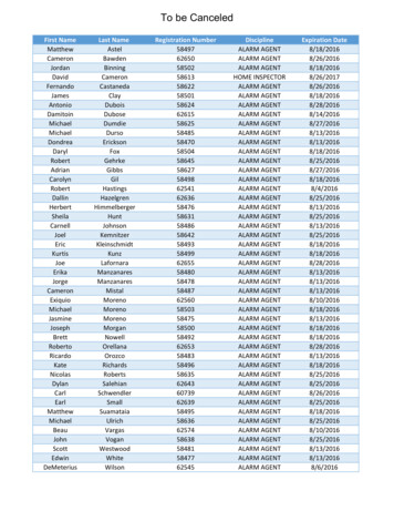
Free SoftwareNessCommsPowerful PC-based programming & operationsoftware Fast and easy installation programming Arm & Disarm remotely with the Virtual Keypad Live zone status mode Download system logs, including extended D8x/D16xlogs not accessible by keypad - up to 80 events Database stores hundreds of clients All relevant control panel manuals are installed withNessComms Free For Trade usersDirect Connect On-SiteSERIALD8x / D16x Deluxe450-246Serial cable101-231 Serial to USBAdapter cableNow the preferred programming tool for many installers,NessComms makes control panel programming as simpleas ticking the boxes.Connect to your control panels on site via modem andlandline. If your standard modem is capable of 300 baudhalf duplex operation it may be suitable for use withNesscomms.orDial-UP via modemPSTNNote:D8x/D16x Deluxe (v8 and later) uses 450-246 serial cable (4 pin)Previous versions of D8x/D16x use 450-185 RS232 cable (3 pin)Modem300 Baudhalf duplexFor the added convenience of on-site programming, D8xand D16x panels also allow direct connect via serial port forfast and easy access by laptop computer. The Ness 450-185Serial Cable is required.Optional ProductPart No. 106-125MiniCENTRALTo Clipsal C-BusThe Ness MiniCENTRAL C-Bus interface combinedwith a Ness D8x or D16x control panel gives youfull two-way C-Bus control and all the features andbenefits of a powerful alarm panel. Fully Clipsal approved C-Bus Enabled Product. Controls up to 255 individual C-Bus lights or outputs.Includes full dimming, On/Off and toggle commands. True 2 way communications on the C-Bus network. Connects directly onto C-Bus without the need for additional hardware such as a PCI Interface. Many D16X events or status changes can control modules on the C-Bus. C-Bus Trigger Control and Enable Control. C-Bus events can control the D8x/D16x. Multiple onboard SERIAL repeater ports means the D8x/D16x panel can also connect to other serial devices whileconnected to MiniCENTRAL.D8x/D16x Control PanelV7.3 or laterOptional ProductNess PDPortable Download ToolPart No. 106-017Ness PD is the fast, easy and simple way to copyprogramming options from one control panel toanother in the field - all without a computer.Ness PD copies and loads data from panel to panelusing the READER header on D8x and D16x panels.Requires D8x/D16x V7.4 or later. Notcompatible with 106-009 D16x C-Bus panel.How to use the NessPD, see page 13. Stores separate data for one D8x and one D16x. Ideal for programming service panels. Use Ness PD to store your default programming for evenfaster commissioning on site.Ness D8x / D16x DELUXE Control Panel – Installation Manual Rev 2.35
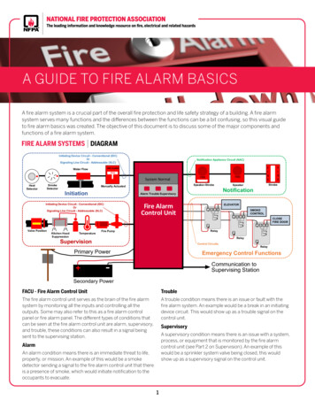
INSTALLATION PROCEDURESESD WarningThe main panel housing and keypad/s should be installed within areas that areprotected by motion sensors or reed switches. A linen closet or cupboard are goodexamples as these are generally located in the centre of the premises. Installing inceiling spaces or other areas where extremes of temperature may be encountered isnot advised.(Electrostatic Discharge).Once properly installed, Ness controlpanels are well protected from ESD.However, take note of the followingprecautions during installation.Positioning of the movement detectors should be considered as the incorrect positionmay cause unwanted alarms. Refer to the motion sensors' installation instructions.The human body can generate staticelectricity when it is insulated from earth- for instance by walking over carpet.1.2.3.4.ESD occurs (and a small shock issometimes felt) if an earthed metalobject is then touched.The installer should be aware that ifhe generates static electricity whileinstalling the panel and then dischargesthis static electricity into the internalcomponents on the main D8/D16 circuitboard or the keypad board, then ESDdamage may occur.5.6.7.8.9.The circuit board should not beunwrapped until it is actually ready to beinstalled.Power-up PROCEDURETo enter Installer Program Mode the first time, power-up with the PROG/TAMPlink OFF. If the PROG/TAMP link is ON and any other 24hr zones are unsealed onpower-up the panel will immediately go into alarm - reset the alarm via keypad orremove power to stop the alarm.Methods to avoid electrostatic build-up.Use a foot strap, a wrist strap,or a grounding mat. The aim isto connect the body to earth todischarge static before it builds up.The connection is a high resistancefor personnel safety.2.If the above is not available, then itis advisable to wear clothing that willminimise the build-up of static.3.Handle circuit boards by the edges.Avoid touching any components onthe board as the integrated circuits,in particular, are not guaranteed bytheir manufacturers to be safe fromESD.4.5.1. Connect the battery first. Observe correct polarity.a) The heartbeat LED will flash continuously to indicate correct operation.b) The Current Limiting Globes should be OFF. If the Globes are glowing, theTELEPHONE LEAD (Supplied)battery connection is reversed. Immediately disconnect the battery and check theConnect to Mode3 socketpolarityLead shown is for Australiaonly. of the battery leads.N.O TAMPER SWITCHALTERNATIVE TAMPER SWITCH WIRING(761-002)Colour:If the heartbeatLED doesnotBLACKflash steadily oroff intermittentlythere may be aForcyclesN.C. TamperSwitchesSuppliedwith Ness ofsirencoversproblem with theinitialisationtheonboard memory. To remedy, in Installer ProgramTELEPHONETo minimise the build-up of static,D8 MAINBOARDavoid walkingaroundas muchas possible while working on theinstallation.LISTENTouch an earthed objecttoLISTEN PINSdischarge any static beforeworkingDiagnostics.Connect anon the installation. 8 Ohm horn speaker toRECEIVER12V DC output 12VZ8Zone 8END OF LINE RESISTORS2. turnon the 2k2EXTernalPowerSupply. The Current Limiting Globes mayCThe default end of line resistor value is 2k2 (2200 Ohms). The EOL value2k2glowslightlytoindicatethatbattery iswithchargingisthefully programmablea choice of correctly.13 resistor values, see programZone 7Z7Z62k2Zone 6Coption P129E.Ness panels are supplied with 2k2 1% tolerance Metal Film resistors.Colour code: Red, Red, Black, Brown, Brown.NOTE:2k2Zone 5Your panel has a dual 17VAC/20VDCpower input.ZONE WIRINGPlease use theonZone 4power supply as shownZone2k2correctNORMALLY CLOSEDCC page 8(N.C.) DEVICESlisten to dialler tones.Z5ZONES 1-8Z4RECEIVERHeader forconnectingoptional RadioInterface.J1 LINKBOX TAMPER & PROGRAM LINK Sealed, normal state Tamper alarm stateZ3Z2Power up with link off to enterinstaller program mode2k2Zone 32k2Zone 22k2Zone 1CAUXAux outputs1-4.Z10VJ1SERIALSERIALRs232 serial portPROGTAMPAUX1AUX2AUX3AUX4 12V0VN.C programmingTAMPER SWITCH (SWI920)Colour: WHITEMode press P95E, P97E & P98E to erase alland reloadfactory defaults.Thenremove power by briefly removing one of the battery leads then re-connect. TheTAMPheartbeatLED should now be flashing continuously, proceed to step 2.0VCNESS LCD KeypadCLKDATCLKCOMCOMInsert the four red PCBposts in the positionsshownMaximum3 keypads 12V 12VREADERUp to 2 x Ness 12V Siren (100-172)OR 3 x 12V Screamer (100-238, 100-004)RESETD8XD or D16XDpcbUp to 2 x Strobe Light (NOI-300)STR“HEARTBEAT” LEDConstantly flashesBATTERYLEADSInsert thewhiteN/C tamper switchPowerZONES 1-8InputNon-PolarityZoneDATBOX TAMPERSWITCHN.C. Contacts(WHITE)READERConnection forup to 3 NessWeigand readersNORMALLY OPEN(N.O.) DEVICES17VAC or20VDC12V DC output for detectors. Auto Reset fuse protected.500mA max. from all 12V outputs. 12VKEYPAD1.Remove the lid and the battery from the base.Securely mount the rear panel housing in a secure location.Run all cabling needed for the installation.Insert the red PCB stand-offs in the housing and then plug the circuit board ontothe stand-offs. See the ESD Warning on this page.Wire the sensors, sirens and accessories to the main board terminal blocks as perthe wiring instructions shown in this installation manual.Fit the battery into the housing but do not connect the battery yet.Insert the panel tamper bracket leads as shown below.Power up as described below.Close the lid and program the panel as required.Up to 3 x Horn Speaker, 8 Ohm (NOI-110)SIREN(supplied)BATTERYACBLACK17VNess 17V AC Plug Pack(Australia only)EARTHEARTH(Yellow/Green stripe)HEATSINKBATTERY CONNECTIONFor 12VBackup7Ah backup batterybattery (BAT210)Suits up to 12Vholder.7Ah battery.OPTIONAL ACCESSORIES FOR D8X & D16XNess RADIO INTERFACENess RELAY BOARDNess OUTPUT EXPANDERWEIGAND READER INTERFACEPart No. 100-200Part No. 106-013Part No. 106-011Part No. 106-012utputsTo A0V 1 12V InTO RECEIVERHEADERTo Aux HeaderNess D8x / D16x DELUXE ControlPanel – InstallationOUTIN617V AC(White & Black)ACRED To READERheaderManualRevNess SERIAL CABLEPart No. 450-1852.3To SERIALheader
inputsOUTputsMonitored ZonesThe Ness D8x and D16x have 8 or 16 fully programmable zoneinputs. (Monitored by end of line resistor).Also, 1 x 24 hour External TAMP input. (Monitored by end of lineresistor). 1 x 24 hour Box Tamper input. (Normally Closed input.Resistor is not required).End of Line ResistorEach zone input must be terminated with an end of line (EOL) resistorunless the zone is disabled by option P125E.12 Volt outputA regulated 13.8 VDC output is available to power detectorsand other equipment. This output is available from two sets ofterminals marked 12V and 0V. This output is protected by anAutomatic Reset fuse.The default EOL resistor value is 2.2k (2200 Ohms). The EOL valueis fully programmable. Available options are 0k (closed circuit), 1k,1.5k, 2.2k, 3.3k, 3.9k, 4.7k, 5.6k, 6.8k, 8.2k, 10k, 12k and 22k. Seeprogramming option P129E.TAMP – Tamper InputThe TAMP input must also be sealed with an end of line resistor. Thisinput is always a 24hr input. The EOL value programed by optionp129E also applies to the TAMP input.Power Input TerminalsThese terminals are for the connection of the external power supply.Your panel has a dual 17VAC/20VDC power input. Please use thecorrect power supply as shown on page 8.Earth (Functional Earth, not a safety Earth)Connect a good earth to this terminal to help protect against damagefrom lightning strikes and static.BatteryThese terminals are for the connection of a sealed lead-acidrechargeable 12Volt battery. Charge current is limited to 350mA.The charge voltage is factory preset at 13.8V. Note: A 12 Volt sealedlead acid rechargeable battery must be connected for correct paneloperation and to ensure the Siren, Strobe and Reset outputs operatecorrectly.The panel will shut down if battery voltage is below 11V and mainspower is off.Observe correct polarity when connecting the battery.(Ness Part Number BAT210 12V 7Ah battery)Current LimitingThe current limiting globes serve to regulate battery charging current.When the battery is fully charged the globes will not glow. Theglobes will glow slightly when recharging the battery after a shortpower outage. If the globes glow very brightly the battery is drawingexcessive current and may be faulty, or the battery is connected inreverse. Check the connections or connect a charged battery.RED 12V 7Ah SealedLead Acid BatteryBLACKOBSERVECORRECT POLARITYA maximum load of 500mA may be connected to these terminals.SirenThe on-board siren driver will drive a maximum of 3 x 8 ohm hornspeakers (Ness Part No. NOI110 or 100-171 Internal Siren). Thewill reset at the end of siren time (P29E) or whenever the panel isreset, whichever comes first.This output is protected by an Automatic Reset fuse.STRA latched 12VDC output for connecting strobe lights.This output will reset after 72 hours (3 days) or when the panel isdisarmed. (D8/D16 versions prior to V4.5 allow indefinite strobeoperation, until the panel is reset).A maximum of 2 x 1 Watt Strobes (Ness Part No. NOI300) can beconnected to this output.This output is protected by an Automatic Reset fuse.ResetA 12V DC output for connecting Ness sirens, piezo sirens orrelays, etc. This output will reset at the end of siren time (P29E) orwhenever the panel is reset, whichever comes first.A maximum of 3 x 12V piezo screamers (Ness Part No. 100-238,100-004) or 2 X Ness Piezo (Part No 100-172) can be connected tothis output.This output is protected by an Automatic Reset fuse.AUX headerThe Aux1 to Aux4 outputs are open collector outputs (switchnegative) which can supply a maximum of 100mA. Each Auxoutput can be programmed to perform several different functions.The header also provides a 12V DC output, max. draw 100mA.RS232 SERIAL PORT (4 pin)Two way RS232 serial port for interfacing to a PC or externalautomation products. The serial data is 9600 baud, 8 data bits, noparity, 1 stop bit. Developer's kit available on request.PROG/TAMP – Program Link & Internal Tamper InputThe PROG/TAMP link appears on the two pin J1 header.The PROG/TAMP link has two purposes:1. To enter Installer Program Mode on initial power up. Powerup with the PROG link OFF. The PROG link (or Box Tamper lead)must be ON in operating mode.2. Box Tamper. When used with the Internal Tamper Lead(supplied), PROG/TAMP serves as the 24hr tamper input for thepanel’s internal tamper switch.Replace the PROG Link with the Box Tamper Lead. Connect theInternal Tamper Lead spade terminals directly to the terminals ofthe internal tamper switch (supplied). An end-of-line resistor isNOT required on this input.When PROG/TAMP is used for Internal Tamper, powering up withthe panel’s cover open will enter Installer Program Mode.BATTERYCurrent limitingglobesSIREN LOAD. A maximum output of 2.0A continuous isavailable from the SIREN and RESET outputs and 200mAfrom the STR output.OUTPUT FUSING. The 12V outputs, Siren, Reset andStrobe outputs are protected by Automatic Reset electronic fuses. These outputs will automatically reset oncethe overload is removed.Recommended maximum power load:3 x Horn speakers (SIREN output)2 x Strobe lights (STR output)2 x Ness Internal Sirens (100-172) (RESET output)Note: (This assumes no more than 500mA is being drawn from the12V device outputs).Ness D8x / D16x DELUXE Control Panel – Installation Manual Rev 2.37
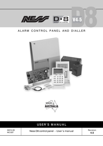
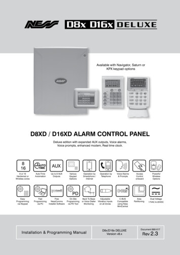
Connection DiagramsTelephone lead (Australia only).Connect to Mode3 socket.TAMPTELEPHONE0VD16x onlyThe default end of line resistor value is 2k2 (2200 Ohms). The EOL value is fullyprogrammable with a choice of 13 resistor values, see program option P129E.Ness panels are supplied with 2k2 1% tolerance Metal Film resistors.Colour code: Red, Red, Black, Brown, Brown.Zone 7Z7Z6Zone 6CZone 5Z5Z4Zone 4CZone 3Z3Z2Zone 2CZone 1Z1 12V 0VAUXAux outputs 1-4and connection foroutput expander/sEND OF LINE RESISTORSD8x & D16xZones 9-16Zone 8CZONE WIRINGDetectorNORMALLY CLOSED(N.C.) DEVICESZoneCDetectorZones 1-8RECEIVERAUX1AUX2AUX3AUX4 12V0VZ8Z9LISTENRECEIVERHeader forconnectingoptional RadioInterface.12V DC output 12VC Z10 Z11 C Z12 Z13 CLISTENAudio Alerts &dialler listen-indiagnostics.Requires separateaudio amp & spkr1. Listen Out 8 ohm spkr2. not used pins 1 & 33. Common4. 12V outALTERNATIVE TAMPER SWITCH WIRINGFor N.C. Tamper SwitchesN.C TAMPER SWITCH (SWI920) Colour: WHITEZ14 Z15 C Z16Main Board Rev8D8x or D16xN.O TAMPER SWITCH(761-002) Colour: BLACKSupplied with Ness siren coversNORMALLY OPEN(N.O.) DEVICESZoneC12V DC output for detectors.Auto Reset fuse protected.500mA max. from all 12V outputs.0V 12VMaximum 3 mixedkeypads or 4 Navigatorkeypads per system.DATKEYPADJ1 LINKBOX TAMPER & PROGRAM LINK Sealed, normal state Tamper alarm stateDATT (Blue)CLK (White)COM (Black) 12V (Red)CLKCOM 12VREADERREADERPower up with link off to enterConnection forinstaller program modeup to 3 NessWeigand readers.Also used for Ness PDPortable Download tool.Navigator keypad* Saturn keypad KPX keypadUp to 2 x Strobe Light (NOI-300)STRUp to 3 x Horn Speaker, 8 Ohm (NOI-110)SIRENBATTERY LEADS(supplied)Polarity is not important for this outputKEYPADBATTERYBLACKRED J1BATTERY CONNECTIONFor 12V 7Ah Backupbattery (Ness BAT210)Keypad Connection (alternative)*Navigator keypad is compatible with D8x/D16x controlpanels version 7.0 or laterHeartbeat LEDBOX TAMPER SWITCH(White) N.C. contactsConnect to J1Dual voltage power input17VAC or 20VDC20V DCPOWER SUPPLYPart No.840-05417VAC or20VDC20VDC Non-polarityA 20VDC power supply is included with most D8x/D16x models (Australia only).This power supply has positive and negative 20VDCoutput however the polarity is not importa
ADsl notiCe: ADSl broadband data can interfere with the operation of your alarm dialler. It is recommended that a quality ADSl filter be installed as per the filter manufacturer's guidelines in premises with an alarm dialler installed. Innovative electronic Solutions www.ness.com.au National Customer Service Centre Ph: 1300 551 991