Transcription
3. Heat Exchanger DesignJohn Richard Thome1er mars 2008John Richard Thome (LTCM - SGM - EPFL)Heat transfer - Heat Exchanger Design1er mars 20081 / 41
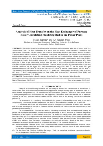
3.1 Function and configuration of heat exchangersHeat exchanger goal : get energy from one fluid mass to another.Simple or composite wall of some kind divides the two flows and provides anelement of thermal resistance between them.Figure 3.1 Heat exchange.John Richard Thome (LTCM - SGM - EPFL)Heat transfer - Heat Exchanger Design1er mars 20082 / 41
3.1 Function and configuration of heat exchangersException : Direct-contact form of heat exchangerSteam is bubbled into water. It condenses and the water is heated at the sametime.Figure 3.2 A direct-contact heat exchanger.John Richard Thome (LTCM - SGM - EPFL)Heat transfer - Heat Exchanger Design1er mars 20083 / 41
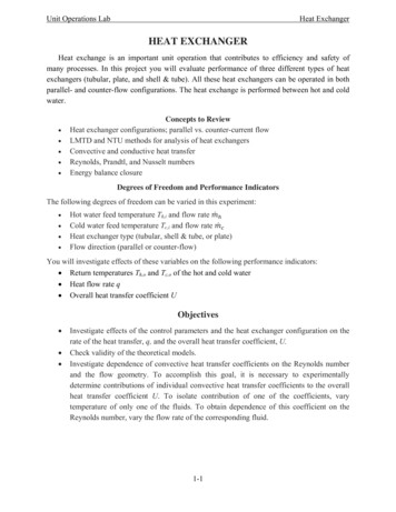
3.1 Function and configuration of heat exchangersThree basic types of heat exchangerThe simple parallel or counterflow configurationFigure 3.3 Parallel or counterflow heat exchangers.John Richard Thome (LTCM - SGM - EPFL)Heat transfer - Heat Exchanger Design1er mars 20084 / 41
3.1 Function and configuration of heat exchangersFigure 3.4 Heliflow compact counterflow heat exchanger. (Photograph coutesy ofGraham Manufacturing Co., Inc., Batavia, New York.)John Richard Thome (LTCM - SGM - EPFL)Heat transfer - Heat Exchanger Design1er mars 20085 / 41
3.1 Function and configuration of heat exchangersThe shell-and-tube configurationFigure 3.3 Two kinds of shell-and-tube heat exchangers.Figure 3.5 Typical commercial one-shell-pass, two-tube-pass heat exchangers.John Richard Thome (LTCM - SGM - EPFL)Heat transfer - Heat Exchanger Design1er mars 20086 / 41
3.1 Function and configuration of heat exchangersThe cross-flow configurationFigure 3.6 c The basic 1 ft/1 ft/2 ft module for a waste heat recuperator. It is aplate-fin, gas-to-air cross-flow heat exchanger with neither flow mixed.John Richard Thome (LTCM - SGM - EPFL)Heat transfer - Heat Exchanger Design1er mars 20087 / 41
3.1 Function and configuration of heat exchangersFour typical single-shell-pass heat exchangers (Nomenclature on page 106)John Richard Thome (LTCM - SGM - EPFL)Heat transfer - Heat Exchanger Design1er mars 20088 / 41
3.1 Function and configuration of heat exchangersFigure 3.7 Four typical heat exchanger configurations. Drawings courtesy of theTubular Exchanger Manufacturers’ Association (TEMA).John Richard Thome (LTCM - SGM - EPFL)Heat transfer - Heat Exchanger Design1er mars 20089 / 41
3.1 Function and configuration of heat exchangersAnother variation on the single-pass configurationFigure 3.9 The temperature distribution through a condenser.John Richard Thome (LTCM - SGM - EPFL)Heat transfer - Heat Exchanger Design1er mars 200810 / 41
3.2 Evaluation of the mean temperature difference in aheat exchangerOverall heat transfer (LMTD)Q UA Tmeanwith a constant U(3.1)Figure 3.8 The temperature variation through single-pass heat exchangers.John Richard Thome (LTCM - SGM - EPFL)Heat transfer - Heat Exchanger Design1er mars 200811 / 41
3.2 Evaluation of the mean temperature difference in aheat exchangerHeat transfer areadQ U T dA(3.2)where T Th TcdQ (ṁcp )h dTh Ch dThdQ (ṁcp )c dTc Cc dTc(3.2 3.3)(3.2 3.3)Where Ch and Cc are the hot and the cold fluid heat capacity ratesThis equation can be integrated from the lefthand side :Parallel flow :Th Th, in Tc Tc, inCounterflow :Th Th, inTc Tc, out"in " is for inlet, "out " is for outlet, "h " is for the hot fluid and "c " is for the coldfluid.John Richard Thome (LTCM - SGM - EPFL)Heat transfer - Heat Exchanger Design1er mars 200812 / 41
3.2 Evaluation of the mean temperature difference in aheat exchangerThe temperatures inside areParallel flow :Th Th, in QCc(Tc Tc, in ) Th, in ChCh(3.4)Th Th, in CcQ(Tc, out Tc ) Th, in ChCh(3.4)Counterflow :Equations (3.4) can be solved for the local temperature differences CcCcTc Tparallel Th Tc Th, in 1 Tc, inChCh CcCc Tcounter Th Tc Th, in 1 Tc Tc, outChChJohn Richard Thome (LTCM - SGM - EPFL)Heat transfer - Heat Exchanger Design(3.5)(3.5)1er mars 200813 / 41
3.2 Evaluation of the mean temperature difference in aheat exchangerSubstitution of these in equation (3.2)Parallel flow :U dAdTc h CcCc 1 T Cc TcChChc, in Th, ini(3.6)i(3.6)Counterflow :U dA h Cc 1 dTcCcCh Tc CcCh Tc, out Th, inEquations (3.6) can be integrated across the exchangerZA0John Richard Thome (LTCM - SGM - EPFL)UdA CcZTc, outTc, indTc[ ]Heat transfer - Heat Exchanger Design(3.7)1er mars 200814 / 41
3.2 Evaluation of the mean temperature difference in aheat exchangerIf U and Cc can be treated as constantParallel flow : 1 CChc Tc, out CChc Tc, in Th, inCcUA 1 ln CcCh 1 CChc Tc, in CChc Tc, in Th, inCounterflow: 1 CChc Tc, out CChc Tc, out Th, inCcUA ln 1 CcCh 1 CChc Tc, in CChc Tc, out Th, inJohn Richard Thome (LTCM - SGM - EPFL)Heat transfer - Heat Exchanger Design(3.8)(3.8)1er mars 200815 / 41
3.2 Evaluation of the mean temperature difference in aheat exchangerwith the help of the definitions of Ta and Tb , given in Fig. 3.8Parallel flow : 1 ln CcCh (Tc, in Tc, out ) Tb Tb UA11 CcCh (3.9)Counterflow :ln Ta 1 CcCh UA(Tc, in Tc, out ) Ta11 CcCh (3.9)Conservation of energy (Qc Qh ) requires thatCcTh, out Th, in ChTc, out Tc, inJohn Richard Thome (LTCM - SGM - EPFL)(3.10)Heat transfer - Heat Exchanger Design1er mars 200816 / 41
3.2 Evaluation of the mean temperature difference in aheat exchangerThen equation (3.9) and equation (3.10) giveParallelflow : Ta Tb} {z (T 11 Ta c, in Tc, out ) (Th, out Th, in ) Tb ln UA ln Tb TbCcCh Counterflow: Ta Ta11ln ln UA Tb Ta Ta TbCcCh(3.11)Finally, we write1Tc, out Tc, in CcQJohn Richard Thome (LTCM - SGM - EPFL)and1Th, in Th, out ChQHeat transfer - Heat Exchanger Design1er mars 200817 / 41
3.2 Evaluation of the mean temperature difference in aheat exchangerin equation (3.11) and we get for either parallel or counterflow Q UA Ta Tbln( Ta / Tb ) (3.12)Logarithmic mean temperature difference (LMTD) Tmean LMTD John Richard Thome (LTCM - SGM - EPFL) Ta Tbln( Ta / Tb )Heat transfer - Heat Exchanger Design(3.13)1er mars 200818 / 41
3.2 Evaluation of the mean temperature difference in aheat exchangerExample 3.1Suppose that we had asked, "What mean radius of pipe would have allowed us tocompute the conduction through the wall of a pipe as though it were a slab ofthickness L r0 ri ?" (see Fig. 3.10). To answer this, we compare TrmeanQ kA 2πkl TLr0 riwith equation (2.21)Q 2πkl TJohn Richard Thome (LTCM - SGM - EPFL)1ln(r0 ri )Heat transfer - Heat Exchanger Design1er mars 200819 / 41
3.2 Evaluation of the mean temperature difference in aheat exchangerExample 3.1 (bis)It follows thatrmean r0 ri logarithmic mean radiusln(r0 /ri )Figure 3.10 Calculation of the mean radius for heat conduction through a pipe.John Richard Thome (LTCM - SGM - EPFL)Heat transfer - Heat Exchanger Design1er mars 200820 / 41
3.2 Evaluation of the mean temperature difference in aheat exchangerExample 3.2Suppose that the temperature difference on either end of a heat exchanger, Ta ,and Tb , are equal. Clearly, the effective T must equal Ta and Tb in thiscase. Does the LMTD reduce to this value ?SOLUTION. If we substitute Ta Tb in equation (3.13), we getLMTD 0Therefore it is necessary to use L’Hospital’s ruleLMTD Ta TbIt follows that the LMTD reduces to the intuitively obvious result in the limit.John Richard Thome (LTCM - SGM - EPFL)Heat transfer - Heat Exchanger Design1er mars 200821 / 41
3.2 Evaluation of the mean temperature difference in aheat exchangerExtended use of the LMTDLimitations :LMTD is restricted to the single-pass parallel and counterflow configurations(can be overcome by adjusting the LMTD for other configurations)Value of U must be negligibly dependent on T to complete the integration ofequation (3.7)John Richard Thome (LTCM - SGM - EPFL)Heat transfer - Heat Exchanger Design1er mars 200822 / 41
3.2 Evaluation of the mean temperature difference in aheat exchangerExtended use of the LMTDFigure 3.11 A typical case of a heat exchanger in which U varies dramatically.John Richard Thome (LTCM - SGM - EPFL)Heat transfer - Heat Exchanger Design1er mars 200823 / 41
3.2 Evaluation of the mean temperature difference in aheat exchangerExtended use of the LMTDCorrection factor, F : is derived analytically from the temperature differencevariation with respect to the log mean temperature difference T t, out Tt, in Ts, in Ts, out Q UA(LMTD) · F , Ts, in Tt, in Tt, out Tt, in {z} {z} P(3.14)Rwhere Tt and Ts are temperatures of tube and shell flows, respectivelyP is the relative influence of the overall temperature difference(Ts, in T t, in) on the tube flow temperature.R, according to eqn. (3.10), equals the heat capacity ratio Ct /CsJohn Richard Thome (LTCM - SGM - EPFL)Heat transfer - Heat Exchanger Design1er mars 200824 / 41
3.2 Evaluation of the mean temperature difference in aheat exchangerExtended use of the LMTDFigure 3.13 The basis of the LMTD in a multipass exchanger, prior to correction.John Richard Thome (LTCM - SGM - EPFL)Heat transfer - Heat Exchanger Design1er mars 200825 / 41
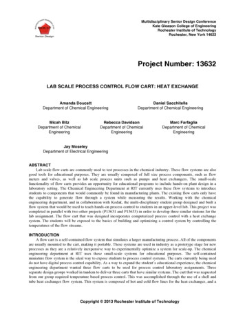
3.2 Evaluation of the mean temperature difference in aheat exchangerFigure 3.14 LMTD correction factors, F, for multipass shelland- tube heatexchangers and one-pass cross-flow exchangers.John Richard Thome (LTCM - SGM - EPFL)Heat transfer - Heat Exchanger Design1er mars 200826 / 41
3.2 Evaluation of the mean temperature difference in aheat exchangerFigure 3.14 LMTD correction factors, F, for multipass shelland- tube heatexchangers and one-pass cross-flow exchangers.John Richard Thome (LTCM - SGM - EPFL)Heat transfer - Heat Exchanger Design1er mars 200827 / 41
3.2 Evaluation of the mean temperature difference in aheat exchangerFigure 3.14 LMTD correction factors, F, for multipass shelland- tube heatexchangers and one-pass cross-flow exchangers.John Richard Thome (LTCM - SGM - EPFL)Heat transfer - Heat Exchanger Design1er mars 200828 / 41
3.2 Evaluation of the mean temperature difference in aheat exchangerFigure 3.14 LMTD correction factors, F, for multipass shelland- tube heatexchangers and one-pass cross-flow exchangers.John Richard Thome (LTCM - SGM - EPFL)Heat transfer - Heat Exchanger Design1er mars 200829 / 41
3.2 Evaluation of the mean temperature difference in aheat exchangerExample 3.45.795 kg/s of oil flows through the shell side of a two-shell pass, four tube-pass oilcooler. The oil enters at 1810 C and leaves at 380 C. Water flows in the tubes,entering at 32.C and leaving at 490 C. In addition, cp poil 2282 J/kg·K and U 416 W/m2 K. Find how much area the heat exchanger must have. SolutionLMTD 40.76 KR 8.412P 0.114with figure (3.14) F 0.92 andQ UA(LMTD)Fwe find the areaA 121.2 m2John Richard Thome (LTCM - SGM - EPFL)Heat transfer - Heat Exchanger Design1er mars 200830 / 41
3.3 Heat exchanger effectivenessLMTD method can only be used if all 4 temperatures are knownNTU method can be used if only the 2 intlet temperatures are knownJohn Richard Thome (LTCM - SGM - EPFL)Heat transfer - Heat Exchanger Design1er mars 200831 / 41
3.3 Heat exchanger effectivenessHeat exchanger effectiveness Ch (Th, in Th, out )Cc (Tc, out Tc, in ) Cmin (Th, in Tc, in )Cmin (Th, in Tc, in )(3.16)where Cmin is smaller of Ch and CcifCh Cc , then Qmax Ch (Th, in Tc, in )Ch Cc , then Qmax Cc (Th, in Tc, in ) is actual heat transferred divided by the maximum heat that could possibly betransferred from one stream to the otherIt follows thatQ Cmin (Th, in Tc, in )John Richard Thome (LTCM - SGM - EPFL)Heat transfer - Heat Exchanger Design(3.17)1er mars 200832 / 41
3.3 Heat exchanger effectivenessNumber of transfer units (NTU)NTU UACmin(3.18)can be viewed as a comparison of the heat capacity of the heat exchanger withthe heat capacity of the flow.Reduce the parallel-flow result from equation (3.9) based on these definitions CminCminCcCmin NTU ln 1 1(3.19)CcChChCcFor the parallel single-pass heat exchangernh io min1 exp NTU 1 CCmaxCmin f NTU,Cmaxmin1 CCmaxJohn Richard Thome (LTCM - SGM - EPFL)Heat transfer - Heat Exchanger Design(3.20)1er mars 200833 / 41
3.3 Heat exchanger effectivenessThe corresponding expression for the counterflow casenh iomin1 exp NTU 1 CCmax nh io minmin1 CCmaxexp NTU 1 CCmax(3.21)Similar calculations give the effectiveness for the other heat exchangerconfigurations.Example 3.5Consider the following parallel-flow heat exchanger specification :cold flow enters at 40o C : Cc 20,000 W/Khot flow enters at 150o C : Ch 10,000 W/KA 30 m2 U 500 W/m2 K.Determine the heat transfer and the exit temperatures.John Richard Thome (LTCM - SGM - EPFL)Heat transfer - Heat Exchanger Design1er mars 200834 / 41
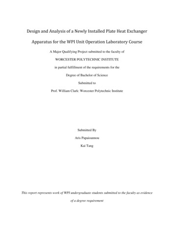
3.3 Heat exchanger effectivenessSolutionIn this case we do not know the exit temperatures, so it is not possible tocalculate the LMTD. Instead, we can go either to the parallel-flow effectivenesschart in Figure (3.16) or to equation (3.20), usingNTU UA 1.5CminCmin 0.5Cmaxand we obtain 0.596. Now from equation (3.17), we find thatQ Cmin (Th, in Tc, in ) 655.6 kWFrom energy balances such as are expressed in equation (3.4), we getTh ,in 84.44o CTh ,out 72.78o CJohn Richard Thome (LTCM - SGM - EPFL)Heat transfer - Heat Exchanger Design1er mars 200835 / 41
3.3 Heat exchanger effectivenessFor a single fluid stream flowing through an isothermal pipe, the equation for theeffectiveness in any configuration must reduce to the same common expression asCmax approaches infinity.In this case becomelimCmax 1 e NTU(3.22)Figure 3.16 The effectiveness of parallel and counterflow heat exchangers.John Richard Thome (LTCM - SGM - EPFL)Heat transfer - Heat Exchanger Design1er mars 200836 / 41
3.3 Heat exchanger effectivenessJohn Richard Thome (LTCM - SGM - EPFL)Heat transfer - Heat Exchanger Design1er mars 200837 / 41
3.3 Heat exchanger effectivenessFigure 3.17 The effectiveness of some other heat exchanger configurations.John Richard Thome (LTCM - SGM - EPFL)Heat transfer - Heat Exchanger Design1er mars 200838 / 41
3.4 Heat exchanger designDetermination of h in a baffled shell remains a problem that cannot be solvedanalytically.Apart from predicting heat transfer, a host of additional considerations must beaddressed in designing heat exchangers. The primary ones are :Minimization of pumping powerpumping power ṁ pρ(3.23)whereṁ is the mass flow rate of the stream p is the pressure drop of the streamρ is the fluid densityDetermining the pressure drop can be relatively difficult.Minimization of fixed costsJohn Richard Thome (LTCM - SGM - EPFL)Heat transfer - Heat Exchanger Design1er mars 200839 / 41
3.4 Heat exchanger designOptimizing the design of an exchanger is not just a matter of making p as smallas possible.Augmentation of heat exchange by employing fins or roughening elements :will invariably increase the pressure dropcan also reduce the fixed cost of an exchanger by increasing U and byreducing the required areacan reduce the required flow rate by increasing the effectiveness and thusbalance the increase of pTaborek’s list of design considerations for a large shell-and-tube exchanger :Choise of fluidsCost of the calculationRough estimate of the size of the heat exchangerEvaluate the heat transfer, pressure drop, and cost of various exchangerconfigurationsJohn Richard Thome (LTCM - SGM - EPFL)Heat transfer - Heat Exchanger Design1er mars 200840 / 41
3.4 Heat exchanger designOnce the exchanger configuration is set :U will be approximately setarea becomes the basic design variablproceed along the lines of Section 3.2 or 3.3.If it is possible to begin with a complete specification of inlet and outlettemperatures,Q U AF (LMTD) {z} {z} {z}C TknowcalculableA can be calculated and the design completedUsually, a reevaluation of U and some iteration of the calculation is needed.More often, we begin without full knowledge of the outlet temperatures :invent an appropriate trial-anderror method to get the areamore complicated sequence of trials for pressure drop and cost optimizationJohn Richard Thome (LTCM - SGM - EPFL)Heat transfer - Heat Exchanger Design1er mars 200841 / 41
John Richard Thome (LTCM - SGM - EPFL) Heat transfer - Heat Exchanger Design 1er mars 2008 22 / 41. 3.2 Evaluation of the mean temperature difference in a heat exchanger Extended use of the LMTD Figure 3.11 A typical case of a