Transcription
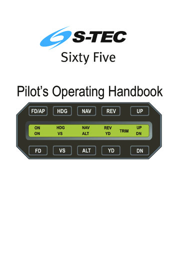
Pilot’s Operating Handbook
S–TECList of Effective Pages* Asterisk indicates pages changed, added, or deleted bycurrent revision.Record of RevisionsRetain this record in front of handbook. Upon receipt of arevision, insert changes and complete table below.Revision NumberRevision Date1stEd.Feb 20, 012ndEd.Jul3rdEd.Aug 30, 074thEd.Nov 01, 094th Ed. Nov 01, 09Insertion Date/Initials31, 01i
S–TECPage Intentionally Blankii4th Ed. Nov 01, 09
S–TECTable of ContentsSec.12Pg.Overview.1–11.1Document Organization.1–31.2Purpose.1–31.3General Control Theory.1–31.4Modes of Operation.1–4Roll Axis Control.1–41.4.2Pitch Axis Control.1–41.4.3Yaw Axis Control.1–41.5Block Diagram.1–41.6Related S-TEC Documents.1–6Pre-Flight Procedures.2–12.131.4.1Pre-Flight Test.2–3In-Flight Procedures.3–13.1Normal Operating Procedures.3–33.1.1Heading (HDG) Mode.3–33.1.2Navigation (NAV) Mode.3–43.1.2.1 Pilot Selectable Intercept Angle.3–73.1.3Altitude Hold (ALT HOLD) Mode.3–83.1.4Vertical Speed (VS) Mode.3–93.1.5Elevator Trim.3–113.1.5.1 Manual Elevator Trim.3–113.1.5.2 Automatic Elevator Trim.3–113.1.5.3 Manual Electric Elevator Trim.3–114th Ed. Nov 01, 09iii
S–TEC3.23.3Precision Approach Procedures.3–153.2.1Straight-In ILS Approach.3–153.2.2ILS Approach with Procedure Turn.3–20Non-Precision Approach Procedures.3–213.3.1Straight-In Back Course Approach.3–213.3.1.1 Pilot Selectable Intercept Angle.3–243.43.543.3.2Back Course Approach with Procedure Turn.3–263.3.3Straight-In LOC Approach.3–323.3.4Straight-In VOR Approach.3–353.3.5LOC Approach with Procedure Turn.3–383.3.6VOR Approach with Procedure Turn.3–44Flight Director Operation.3–503.4.1FD/AP Mode.3–503.4.2FD Mode.3–51Wide Area Augmentation System (WAAS) Procedures.3–513.5.1GPS Approach (with Vertical Guidance).3–513.5.2Missed Approach.3–523.6Yaw Damper Operation.3–523.7Autopilot Disconnect .3–533.8Automatic Trim Disable.3–53Operating Parameters.4–14.1Roll Axis Limits.4–34.2Pitch Axis Limits.4–35Glossary.5–1iv4th Ed. Nov 01, 09
S–TECList of FiguresFig.Pg.1–1System Sixty Five Block Diagram.1–51–2Yaw Damper Block Diagram.1–61–3Flight Director Block Diagram.1–62–1AP Display, RDY for Operation.2–42–2AP Display, Turn Coordinator Failure, RDY Does Not Appear.2–52–3AP Display, Programmer ON.2–72–4AP Display, HDG Mode Engaged.2–82–5AP Display, HDG and ALT HOLD Modes Engaged.2–102–6AP Display, HDG and VS Modes Engaged.2–122–7AP Display, NAV and ALT HOLD Modes Engaged, SOFT Condition.2–152–8AP Display, HDG and ALT HOLD Modes Engaged,TRIM UP Required.2–162–9AP Display, HDG and ALT HOLD Modes Engaged,TRIM DN Required.2–182–10 AP Display, YD Mode Engaged.2–213–1AP Display, HDG Mode Engaged.3–33–2AP Display, NAV Mode Engaged.3–43–3AP Display, NAV Mode Engaged, CAP Condition.3–63–4AP Display, NAV Mode Engaged, CAP SOFT Condition.3–63–5AP Display, NAV Mode Engaged, SOFT Condition.3–63–6AP Display, HDG Mode Engaged, NAV Mode Armed.3–83–7AP Display, HDG and ALT HOLD Modes Engaged.3–93–8AP Display, HDG and VS Modes Engaged.3–104th Ed. Nov 01, 09v
S–TEC3–9AP Display, TRIM UP Required.3–123–10 AP Display, TRIM DN Required.3–133–11 AP Display, Manual Electric Trim in Progress.3–143–12 AP Display, NAV APR and ALT HOLD Modes Engaged.3–153–13 AP Display, NAV APR and ALT HOLD Modes Engaged,GS Mode Armed.3–173–14 AP Display, NAV APR and ALT HOLD Modes Engaged,GS Mode Disabled.3–183–15 AP Display, NAV APR and GS Modes Engaged.3–193–16 Straight-In ILS Approach.3–203–17 AP Display, REV APR Mode Engaged,Before LOC Back Course Intercept.3–223–18 AP Display, REV APR Mode Engaged,Track LOC Back Course Inbound.3–233–19 Straight-In Back Course Approach.3–243–20 AP Display, HDG Mode Engaged, REV APR Mode Armed.3–253–21 AP Display, NAV APR Mode Engaged,Before LOC Back Course Intercept.3–273–22 AP Display, NAV APR Mode Engaged,Track LOC Back Course Outbound.3–283–23 AP Display, REV APR Mode Engaged,Before LOC Back Course Intercept.3–293–24 AP Display, REV APR Mode Engaged,Track LOC Back Course Inbound.3–303–25 Back Course Approach with Procedure Turn.3–313–26 AP Display, NAV APR Mode Engaged,Before LOC Front Course Intercept.3–323–27 AP Display, NAV APR Mode Engaged,Track LOC Front Course Inbound.3–33vi4th Ed. Nov 01, 09
S–TEC3–28 Straight-In LOC Approach.3–343–29 AP Display, NAV Mode Engaged,Before VOR Front Course Intercept.3–353–30 AP Display, NAV Mode Engaged,Track VOR Front Course Inbound.3–363–31 Straight-In VOR Approach.3–373–32 AP Display, REV APR Mode Engaged,Before LOC Front Course Intercept.3–393–33 AP Display, REV APR Mode Engaged,Track LOC Front Course Outbound.3–403–34 AP Display, NAV APR Mode Engaged,Before LOC Front Course Intercept.3–413–35 AP Display, NAV APR Mode Engaged,Track LOC Front Course Inbound.3–423–36 LOC Approach with Procedure Turn.3–433–37 AP Display, REV Mode Engaged,Before VOR Front Course Intercept.3–453–38 AP Display, REV Mode Engaged,Track VOR Front Course Outbound.3–463–39 AP Display, NAV Mode Engaged,Before VOR Front Course Intercept.3–473–40 AP Display, NAV Mode Engaged,Track VOR Front Course Inbound.3–483–41 VOR Approach with Procedure Turn.3–493–42 FD Parallax Adjustment.3–503–43 FD Display, FD/AP Mode Engaged.3–503–44 FD Display, FD Mode Engaged.3–513–45 Yaw Damper Trim Knob.3–524th Ed. Nov 01, 09vii
S–TECList of TablesTable2–1viiiPg.Pre-Flight Test.2–34th Ed. Nov 01, 09
S–TECSECTION 1OVERVIEW4th Ed. Nov 01, 091-1
S–TECPage Intentionally Blank1-24th Ed. Nov 01, 09
S–TEC1.1 Document OrganizationSection 1 OverviewSection 2 Pre-Flight ProceduresSection 3 In-Flight ProceduresSection 4 Operating ParametersSection 5 Glossary1.2 PurposeThis Pilot's Operating Handbook (POH) provides Pre-Flight and In-Flightoperating procedures for the S-TEC System Sixty Five Autopilot (AP).Note:This POH must be carried in the A/C and made available to the pilot atall times. It can only be used in conjunction with the Federal AviationAdministration (FAA) approved Aircraft Flight Manual (AFM) or Aircraft FlightManual Supplement (AFMS). Refer to the applicable AFM or AFMS forA/C specific information, such as unique ground tests, limitations, andemergency procedures.Note:The System Sixty Five autopilot is a tool provided to aircraft owners, thatserves to assist them with cockpit workload management. The ability of theautopilot to provide optimum assistance and performance is directlyproportional to the pilot's knowledge of its operating procedures. Therefore,it is highly recommended that the pilot develop a thorough understanding ofthe autopilot, its modes, and operating procedures in Visual MeteorologicalConditions (VMC), prior to using it under Instrument Flight Rules (IFR).1.3 General Control TheoryThe System Sixty Five is a rate based autopilot. When in control of the roll axis,the autopilot senses turn rate, as well as closure rate to the selected course,along with the non-rate quantities of heading error, course error, and coursedeviation indication. When in control of the pitch axis, the autopilot sensesvertical speed, acceleration, and closure rate to the selected glideslope, alongwith the non-rate quantities of altitude and glideslope deviation indication. Thesesensed data provide feedback to the autopilot, which processes them in order tocontrol the aircraft through the use of mechanisms coupled to the controlsystem. In most aircraft, the roll servo is coupled to the ailerons. The pitchservo is coupled to the elevator. Activation of roll axis control must alwaysprecede activation of pitch axis control.The autotrim function senses when the aircraft needs to be trimmed about thepitch axis, and responds by driving the trim servo in the proper direction toprovide trim. The trim servo is coupled to the elevator trim tabs.The optional yaw damper senses excessive adverse yaw about the yaw axis,and responds by driving the yaw servo in the proper direction to providedamping. The yaw servo is coupled to the rudder.The optional flight director is a display of the flight profile.4th Ed. Nov 01, 091-3
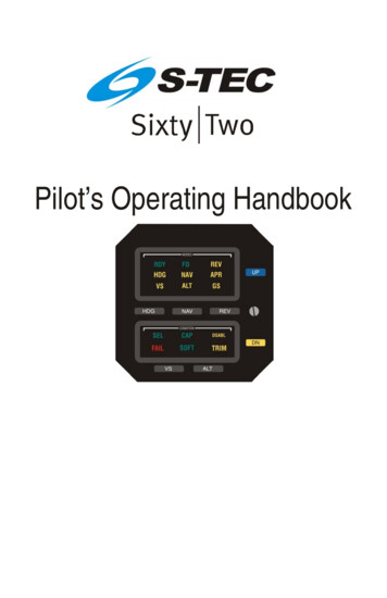
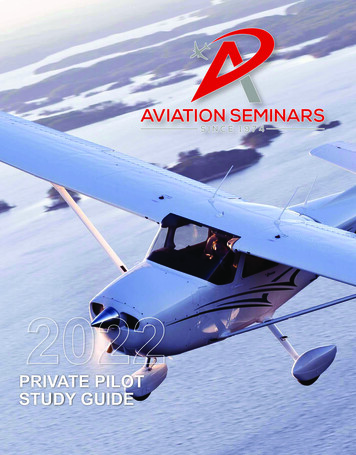
S–TEC1.4 Modes of Operation1.4.1 Roll Axis ControlHeading (HDG) ModeUsed to Turn onto a Selected Heading and Hold itNavigation (NAV) ModeUsed to Intercept and Track a VOR CourseNavigation Approach (NAV APR) ModeUsed to Intercept and Track a LOC Front Course InboundReverse (REV) ModeUsed to Intercept and Track the Reciprocal of a Specified VOR CourseReverse Approach (REV APR) ModeUsed to Intercept and Track a LOC Back Course Inbound1.4.2 Pitch Axis ControlAltitude Hold (ALT HOLD) ModeUsed to Hold AltitudeVertical Speed (VS) ModeUsed to Hold Vertical SpeedGlideslope (GS) ModeUsed to Intercept and Track Glideslope1.4.3 Yaw Axis ControlYaw Damper (YD) ModeUsed to Dampen Excessive Adverse Yaw1.5 Block DiagramThe System Sixty Five Block Diagram is shown in Fig. 1-1.The Yaw Damper Block Diagram is shown in Fig. 1-2.The Flight Director Block Diagram is shown in Fig. 1-3.1-44th Ed. Nov 01, 09
S–TECFig. 1-1. System Sixty Five Block Diagram4th Ed. Nov 01, 091-5
S–TECFig. 1-2. Yaw Damper Block DiagramFig. 1-3. Flight Director Block Diagram1.6 Related S-TEC DocumentsPOH, ST-901 GPSS Converter, PN 87991-64th Ed. Nov 01, 09
S–TECSECTION 2PRE-FLIGHT PROCEDURES4th Ed. Nov 01, 092-1
S–TECPage Intentionally Blank2-24th Ed. Nov 01, 09
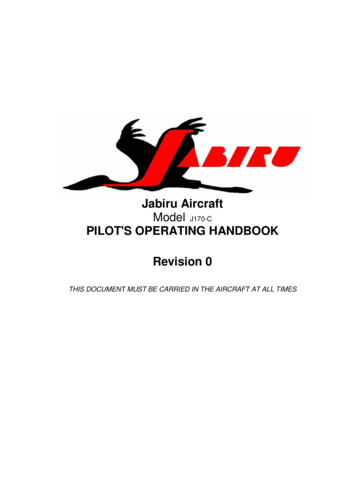
S–TEC2.1 Pre-Flight TestPrior to takeoff and with engine running, perform the actions shown in Table 2-1.For each action, verify the corresponding response where applicable.Table 2-1. Pre-Flight Test (continued on page 2-6)ACTIONRESPONSE1. Set Trim Master Switch to OFFposition (if installed).------2. Set Battery Master Switch to ONposition.------3. Set Avionics Master Switch to ONposition.RDY annunciation only appears onAP display within 3 minutes, asshown in Fig. 2-1.Note:Shou ld a Turn Coord inator failure be detected, the RDYannunciat ion w ill not appear as shown in Fig. 2-2, and the autopilot will notoperate.4. Move A/C Control Wheel forwardand aft, to sense its freedom ofmovement about pitch axis.------5. Press/HoldUPswitchonProgrammer, while maintaining agrasp on A/C Control Wheel.Pitch Servo initially engages, assensed by the reduced freedom ofA/C Control Wheel movement aboutpitch axis, and Audible Alert sounds asteady tone.Note: This verifies g-force limit switchoperation.After 2 seconds Pitch Servodisengages, as sensed by theincreased freedom of A/C ControlWheel movement about pitch axis.6. Release UP switch.4th Ed. Nov 01, 09Audible Alert is squelched.2-3
S–TECFig. 2-1. AP Display, RDY for Operation2-44th Ed. Nov 01, 09
S–TECFig. 2-2. AP Display, Turn Coordinator Failure, RDY Does Not Appear4th Ed. Nov 01, 092-5
S–TECTable 2-1. Pre-Flight Test (continued from page 2-3)ACTIONRESPONSE7. Press/HoldDNswitchonProgrammer, while maintaining agrasp on A/C Control Wheel.Pitch Servo initially engages, assensed by the reduced freedom ofA/C Control Wheel movement aboutpitch axis, and Audible Alert sounds asteady tone.Note: This verifies g-force limit switchoperation.After 2 seconds Pitch Servodisengages, as sensed by theincreased freedom of A/C ControlWheel movement about pitch axis.8. Release DN switch.Audible Alert is squelched.9. Press FD/AP switch.ON annunciation appears on APdisplay, as shown in Fig. 2-3.10. Set Heading Bug under LubberLine.------11. Move A/C Control Wheel left andright, to sense its freedom ofmovement about roll axis.------12. Press HDG mode selector switchto engage heading mode, and thenpress YD mode selector switch todisengage yaw damper mode (only ifyaw damper is installed).HDG annunciation appears on APdisplay, whereas RDY and YD areextinguished as shown in Fig. 2-4.13. Attempt movement ofControl Wheel left and right.A/CControlWheel’sreducedfreedom of movement indicates thatRoll Servo is engaged.A/CVerify that Roll Servo can beoverridden.If not, pull AutopilotCircuit Breaker and do not use.2-64th Ed. Nov 01, 09
S–TECFig. 2-3. AP Display, Programmer ON4th Ed. Nov 01, 092-7
S–TECFig. 2-4. AP Display, HDG Mode Engaged2-84th Ed. Nov 01, 09
S–TECTable 2-1. Pre-Flight Test (continued from page 2-6)ACTION14. Turn Heading Bug to theside of Lubber Line.RESPONSEleftA/C Control Wheel turns to the left.15. Turn Heading Bug to the rightside of Lubber Line.A/C Control Wheel turns to the right.16. Set Heading Bug under LubberLine.A/C Control Wheel stops.17. Move A/C Control Wheel forwardand aft, to sense its freedom ofmovement about pitch axis.------18. Press ALT mode selector switchto engage altitude hold mode.ALT annunciation appears on APdisplay, as shown in Fig. 2-5.19. Attempt movement ofControl Wheel forward and aft.A/CControlWheel’sreducedfreedom of movement indicates thatPitch Servo is engaged.A/CVerify that Pitch Servo can beoverridden.If not, pull AutopilotCircuit Breaker and do not use.20. Move A/C Control Wheel untilelevator is in neutral position.------21. Press/Hold UP switch.A/C Control Wheel moves in aftdirection, while Audible Alert soundsa steady tone.22. Release UP switch.A/C Control Wheel continues movingin aft direction, but Audible Alert issquelched.4th Ed. Nov 01, 092-9
S–TECFig. 2-5. AP Display, HDG and ALT HOLD Modes Engaged2-104th Ed. Nov 01, 09
S–TECTable 2-1. Pre-Flight Test (continued from page 2-9)ACTIONRESPONSE23. Press/Hold DN switch.A/C Control Wheel slows to a stop inaft direction, and then moves inforward direction while Audible Alertsounds a steady tone.24. Release DN switch.A/C Control Wheel continues movingin forward direction, but Audible Alertis squelched.25. Press VS mode selector switchto engage vertical speed mode.A/C Control Wheel stops.VS annunciation appears on APdisplay, whereas ALT is extinguishedas shown in Fig. 2-6.26. Press/Hold UP switch.A/C Control Wheel moves in aftdirection, while Audible Alert soundsa steady tone.27. Release UP switch.A/C Control Wheel continues movingin aft direction, but Audible Alert issquelched.28. Press/Hold DN switch.A/C Control Wheel slows to a stop inaft direction, and then moves inforward direction while Audible Alertsounds a steady tone.29. Release DN switch.A/C Control Wheel continues movingin forward direction, but Audible Alertis squelched.30. Press ALT mode selector switchto engage altitude hold mode.A/C Control Wheel stops.ALT annunciation appears on APdisplay, whereas VS is extinguished.4th Ed. Nov 01, 092-11
S–TECFig. 2-6. AP Display, HDG and VS Modes Engaged2-124th Ed. Nov 01, 09
S–TECTable 2-1. Pre-Flight Test (continued from page 2-11)ACTIONRESPONSENote:If it is not possible to select a local VOR frequency on Navigation Receiver,then proceed to step 44. Otherwise, proceed to step 31.31. Select local VOR frequency onNavigation Receiver.------Note:Proceed to either step 32 (HSI) or step 38 (DG).32. Turn Course Pointer until CDIneedle is centered.------33. Turn A/C until Course Pointer isunder Lubber Line, to null courseerror input to autopilot.------34. Press NAV mode selector switchto engage navigation mode.NAV and SOFT annunciations appearon AP display, whereas HDG isextinguished as shown in Fig. 2-7.35. Turn Course Pointer left untilCDI needle deflection is 2 dots rightof center.A/C Control Wheel turns to the right.36. Turn Course Pointer right untilCDI needle deflection is 2 dots left ofcenter.A/C Control Wheel turns to the left.37. Turn Course Pointer left until CDIneedle deflection is centered.A/C Control Wheel stops.Note: Proceed to step 43.4th Ed. Nov 01, 092-13
S–TECTable 2-1. Pre-Flight Test (continued from page 2-13)ACTIONRESPONSE38. Turn OBS until CDI needle iscentered.------39. Press NAV mode selector switchto engage navigation mode.NAV and SOFT annunciations appearon AP display, whereas HDG isextinguished as shown in Fig. 2-7.40. Turn OBS until CDI needledeflection is 2 dots right of center.A/C Control Wheel turns to the right.41. Turn OBS until CDI needledeflection is 2 dots left of center.A/C Control Wheel turns to the left.42. Turn OBS until CDI needle iscentered.A/C Control Wheel stops.43. Press HDG mode selector switchto engage heading mode.HDG annunciation appears on APdisplay, whereas NAV and SOFT areextinguished.44. Move A/C Control Wheel as farforward as possible.After 3 seconds, TRIM and UPannunciations appear on AP displayas shown in Fig. 2-8, and AudibleAlert sounds a steady tone.After 7 seconds, TRIM and UPannunciations flash, and Audible Alertbecomes periodic.45. Move A/C Control Wheel aft untilTRIM and UP annunciations areextinguished.2-14Audible Alert is squelched.4th Ed. Nov 01, 09
S–TECFig. 2-7. AP Display, NAV and ALT HOLD Modes Engaged, SOFT Condition4th Ed. Nov 01, 092-15
S–TECFig. 2-8. AP Display, HDG and ALT HOLD Modes Engaged, TRIM UP Required2-164th Ed. Nov 01, 09
S–TECTable 2-1. Pre-Flight Test (continued from page 2-14)ACTIONRESPONSE46. Move A/C Control Wheel as faraft as possible.After 3 seconds, TRIM and DNannunciations appear on AP displayas shown in Fig. 2-9, and AudibleAlert sounds a steady tone.After 7 seconds, TRIM and DNannunciations flash, and Audible Alertbecomes periodic.47. Move A/C Control Wheel forwarduntil TRIM and DN annunciations areextinguished.Audible Alert is squelched.Note:Although autotrim is standard equipment, it cannot be installed on selectedaircraft models. If autotrim is installed, then proceed to step 48. Otherwise,proceed to step 62.48. Set Trim Master Switch to ONposition.------49. Move A/C Control Wheel as farforward as possible.After 2-3 seconds, Elevator TrimWheel begins to run nose up withincreasing speed.50. Move A/C Control Wheel aft untilElevator Trim Wheel stops.------51. Move A/C Control Wheel as faraft as possible.After 2-3 seconds, Elevator TrimWheel begins to run nose down withincreasing speed.52. Move A/C Control Wheel forwarduntil Elevator Trim Wheel stops.------4th Ed. Nov 01, 092-17
S–TECFig. 2-9. AP Display, HDG and ALT HOLD Modes Engaged, TRIM DN Required2-184th Ed. Nov 01, 09
S–TECTable 2-1. Pre-Flight Test (continued from page 2-17)ACTION53. Press momentarily either forwardor aft on both segments of ManualElectric Trim Switch.RESPONSEAutopilot disconnects as follows:RDY annunciation appears flashingand ON remains, whereas all otherannunciations are extinguished.After 5 seconds, RDY annunciationstops flashing but remains.54. Press/Hold forward on bothsegments of Manual Electric TrimSwitch.Elevator Trim Wheel runs nose downat full speed, and TRIM annunciationappears flashing on AP display.55. Press/Hold AP DISC / TRIM INTRSwitch.Elevator Trim Wheel stops.56. ReleaseSwitch.Elevator Trim Wheel resumes runningnose down at full speed.AP DISC / TRIM INTR57. Release Manual Electric TrimSwitch.Elevator Trim Wheel stops.TRIM annunciation is extinguished.58. Press/Hold aft on both segmentsof Manual Electric Trim Switch.Elevator Trim Wheel runs nose up atfull speed, and TRIM annunciationappears flashing on AP display.59. Press/Hold AP DISC / TRIM INTRSwitch.Elevator Trim Wheel stops.60. ReleaseSwitch.Elevator Trim Wheel resumes runningnose up at full speed.AP DISC / TRIM INTR61. Release Manual Electric TrimSwitch.Elevator Trim Wheel stops.TRIM annunciation is extinguished.4th Ed. Nov 01, 092-19
S–TECTable 2-1. Pre-Flight Test (continued from page 2-19)ACTIONRESPONSENote:If autopilot is equipped with a Yaw Damper, then proceed to step 63.Otherwise, proceed to step 72.62. Press AP DISC / TRIM INTRSwitch.Autopilot disconnects as follows:RDY annunciation appears flashingand ON remains, whereas all otherannunciations are extinguished.After 5 seconds, RDY annunciationstops flashing but remains.Note:If autopilot is equipped with a Yaw Damper, then proceed to step 63.Otherwise, proceed to step 72.63. Actuate A/C Rudder Pedalsalternately in succession, to sensetheir freedom of movement about yawaxis.------64. Press YD mode selector switchto engage yaw damper mode.YD annunciation appears on APdisplay, as shown in Fig. 2-10.65. Turn Yaw Trim Knob until A/CRudder Pedals stop.------66. Attempt actuation of A/C RudderPedals alternately in succession.A/C Rudder Pedals’ reduced freedomof movement indicates that YawServo is engaged.Yaw Servo can be overridden. If not,pull Autopilot Circuit Breaker and donot use.2-204th Ed. Nov 01, 09
S–TECFig. 2-10. AP Display, YD Mode Engaged4th Ed. Nov 01, 092-21
S–TECTable 2-1. Pre-Flight Test (continued from page 2-20)ACTIONRESPONSE67. Turn Yaw Trim Knob fully CCW.Left A/C Rudder Pedal slowly movesforward.68. Turn Yaw Trim Knob fully CW.Right A/C Ruddermoves forward.69. Turn Yaw Trim Knob CCW untilA/C Rudder Pedals stop.Pedalslowly------70. Press YD mode selector switchto disengage yaw damper mode.YD annunciation is extinguished.71. Actuate A/C Rudderalternately in succession.A/C Rudder Pedals’ increasedfreedom of movement indicates thatYaw Servo is disengaged.72. Trim A/C for takeoff.2-22Pedals------4th Ed. Nov 01, 09
S–TECSECTION 3IN-FLIGHT PROCEDURES4th Ed. Nov 01, 093-1
S–TECPage Intentionally Blank3-24th Ed. Nov 01, 09
S–TEC3.1 Normal Operating Procedures3.1.1 Heading (HDG) ModeSet the Heading Bug to the desired heading on the compass card (HSI or DG),and then press the HDG mode selector switch to engage the heading mode.The HDG annunciation will appear as shown in Fig. 3-1, to acknowledge thatthis mode is engaged. The autopilot will turn the aircraft onto the selectedheading and hold it. A new heading can be subsequently selected by setting theHeading Bug to it.Fig. 3-1. AP Display, HDG Mode Engaged4th Ed. Nov 01, 093-3
S–TEC3.1.2 Navigation (NAV) ModeSelect the VOR frequency on the Navigation Receiver.Heading System HSISet Course Pointer to desired course on compass card.Heading System DGSet Heading Bug and OBS to desired course on each respective compass card.Press the NAV mode selector switch to engage the navigation mode. TheNAV annunciation will appear as shown in Fig. 3-2, to acknowledge that thismode is engaged.Fig. 3-2. AP Display, NAV Mode Engaged3-44th Ed. Nov 01, 09
S–TECIf the Course Deviation Indication (CDI) is at full scale (100%) needle deflectionfrom center, then the autopilot will establish the aircraft on a 45 interceptangle relative to the selected course. Even if CDI needle deflection is less than100%, the autopilot may still establish an intercept angle of 45 , provided thatthe aircraft's closure rate to the selected course is sufficiently slow. Otherwise,the intercept angle will be less than 45 .As the aircraft approaches the selected course, the autopilot senses thecorresponding rate at which the CDI needle approaches center (closure rate), inorder to initiate the aircraft's turn onto the course at the proper point, and therebyprevent overshoot. The point at which this turn begins is variable, being furtherfrom the course at faster closure rates, and closer to the course at slowerclosure rates. Although closure rate is principally a function of groundspeed, thedistance of the aircraft from the VOR station also has an effect. Nevertheless,the turn will always begin between 100% and 20% CDI needle deflection.During this stage of the intercept sequence, the autopilot operates at maximumgain and sensitivity to closure rate. In addition, it limits the aircraft's turn rate to90% of a standard rate turn, although for some higher performance (turboprop)aircraft this is 75%.When the aircraft arrives at 15% CDI needle deflection, the course is captured.At that instant, a step reduction in autopilot gain occurs, so that the CoursePointer (HSI) or Heading Bug (DG) has sufficient authority to complete theintercept. In addition, the sensitivity to closure rate is reduced. The overallauthority of the autopilot during this stage of the intercept sequence is called theCAP condition, which is acknowledged by the appearance of the CAPannunciation as shown in Fig. 3-3.Fifteen seconds after course capture, a second step reduction in autopilot gainoccurs, to limit the aircraft's turn rate to 45% of a standard rate turn, although forsome higher performance (turboprop) air
proportional to the pilot's knowledge of its operating procedures. Therefore, it is highly recommended that the pilot develop a thorough understanding of the autopilot, its modes, and operating procedures in Visual Meteorological Conditions (VMC), prior to using it under Instrument Flight Rules (IFR). 1.3 General Control Theory