Transcription
The Pennsylvania Housing Research CenterKitchen Ventilation Systems: Part 2Providing Adequate Makeup AirBuilder Brief: April 2012Anthony C. Jellen, PE & Brian M. Wolfgang, EIT, Michael A. Turns, MSINTRODUCTIONThe first Builder Brief of this two-part seriesdiscussed the relationship between kitchen exhaustrates, house tightness, and house depressurization.That brief also provided an overview of the healthand safety hazards associated with housedepressurization and the presence of combustionappliances.In this brief, we provide design guidance forintroducing makeup air for a residential kitchenexhaust system using three common techniques: (1)engineered openings, (2) HVAC-integrated airsystems, and (3) dedicated makeup air units. We willalso discuss common design practices for meetingthe interlocking and closure requirements of the2009 International Residential Code (IRC) SectionM1503.4.and require larger exhaust systems leading to higheroperation costs, and increased risk of housedepressurization and associated hazards. In addition,every cubic foot of exhausted air is a cubic foot ofmakeup air that must be heated or cooled at thehomeowner’s expense.The required exhaust rate for standard, low-powered,residential kitchen ranges is typically specified perlinear foot of range. Table 1 shows recommendedexhaust rate per linear foot (LF), according to theHome Ventilating Institute (HVI).Table 1. HVI recommended and minimum ventilationrates for kitchen range hoods.LOCATIONWallIslandRec. Vent. Rateper LF of Range100 CFM150 CFMMin. Vent. Rateper LF of Range40 CFM50 CFMPROPER RANGE EXHAUST SELECTIONThe objective of a kitchen range exhaust system is tocapture moisture and airborne contaminants createdduring cooking, and vent them to the outside. Theselection of an exhaust system is largely dependenton the size and type of range, and its intended use.Wall mounted hoods are the most common exhaustsystem used in the residential kitchen; however,island canopy hoods and downdraft systems haverisen in popularity in recent years.The goal of an exhaust system specifier should be toprovide an adequate, but not excessive, amount ofexhaust without jeopardizing occupant safety orcomfort. First, a homeowner or homebuyer shouldassess their cooking habits and select appliancesbased on need rather than a “bigger is better”mentality. Larger appliances demand more powerKitchens that contain high-powered, commercialstyle cooking equipment will require a higherexhaust rate. The installer should always check theequipment specifications for exhaust systemrecommendations. If no information is available,equipment should be classified by type, applicationand power consumption, and sized in accordancewith the ASHRAE Handbook (HVAC Applicationssection), or other reputable source.MAKEUP AIR REQUIREMENTSOnce the exhaust rate is specified, the designer candetermine the need for makeup air. As discussed inPart 1 of this Builder Brief series, Section M1503.4of the 2009 IRC requires makeup air at a rateroughly equal to the exhaust rate for systems capableof exceeding 400 CFM. That brief demonstrated that1
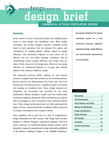
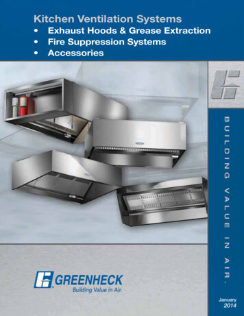
the 400 CFM threshold, although seeminglyarbitrary, is appropriate for tight to moderately tightresidential enclosures. Figure 4 in Part 1, shows thatthe potential for depressurization exists at almost anyexhaust rate; therefore, it is prudent for a designer toconduct some type of risk assessment for allinstallations. See Part 1 of this Builder Brief series,or ASTM E1998, Standard Guide for AssessingDepressurization Induced Backdrafting and Spillagefrom Vented Combustion Appliances.interior pressure becomes increasingly negative. Theeffects are hard to predict and highly dependent onthe location of the opening and connectivity ofrooms within the house. Mechanical systemsintroduce makeup air into the house by a fan, whereit can be routed directly to the kitchen, or drawn intothe central HVAC system and distributed throughoutthe house. When properly installed, a fan-assistedsolution should eliminate any adverse pressureeffects created by the exhaust system. Figure 1illustrates the effects of both methods on buildingpressurization and the neutral pressure plane.INTRODUCING MAKEUP AIR#4#3Properly introducing makeup air is essential toensuring a safe, comfortable, and efficient home.Improperly specified makeup air systems can lead touncomfortabledrafts,overstressedHVACequipment, mold, and house depressurization. An illconceived exhaust and makeup air system design canbe expensive as well as non-functional.To maintain occupant comfort, most design guidancerecommends providing a makeup air supplytemperature within 10 degrees F of the roomtemperature. For example, if a house is maintainedat 70 degrees F in the wintertime, the makeup airshould be provided at a supply temperature of noless than 60 degrees F.Design considerations for makeup air systems thatexceed supply rates of 400 CFM are similar to thatof a commercial kitchen or industrial exhaustsystem. Thus, it is highly recommended that aHVAC expert be involved in the design process.Significant quantities of makeup air will increaseloads placed on the central HVAC system. TheHVAC system or building enclosure will likelyrequire modification to function efficiently with thenewly introduced makeup air.Makeup air can be introduced in many ways withvarying degrees of effectiveness. The two mostcommon methods are engineered openings andmechanical systems. Engineered openings in theenclosure allow air to be drawn into the house FFigure 1. Comparison of air movement in a house with anengineered opening (Scenario #3) versus a house withfan-assisted a makeup air system (Scenario #4). InScenario #3, the neutral pressure plane rises, and the levelof house depressurization is less predictable. In Scenario#4, pressures in the house mirror those when no exhaustor makeup air systems are installed (natural conditions).ENGINEERED OPENINGSAn engineered opening is an intentional openingplaced in the enclosure for the purposes oftransferring air between the interior and exterior of abuilding. An opening could be as simple as a holeplaced through an exterior wall, or may includeductwork to a remote space such as the kitchen.Figure 1 shows a typical configuration for anengineered opening that supplies makeup air directlyinto the kitchen.Providing one or more engineered openings in theenclosure is a simple and inexpensive technique tointroduce makeup air. The effects are similar to that2
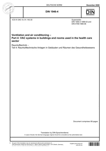
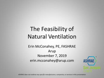
Motorized damper Closed except duringperiods of exhaustMakeup airdistributed tokitchenIntake hood withinsect screenFresh air into houseToe-kick diffuser orgrilleDuct – Properly sized,R-8 insulation preferredFigure 2. Typical engineered opening. The engineered opening in this diagram allows makeup air for a range hood to enterthe house into the same room that the exhaust air leaves. This will help to alleviate negative pressure that may result fromrange hood operation.of opening a door or window. Typically a damper isincorporated into the opening design to minimizeheating and cooling costs and to ensure airflow onlyduring times of depressurization or exhaustoperation.Airflow through engineered openings dependsprimarily on the area of the opening and pressuredifference across the opening. The pressuredifferential depends on all the factors discussed inTable 2. Airflow through an engineered opening.Pressure(Pa)12345678910Airflow (CFM) Based on Opening Size4 in6 in8 in10 in12 4441911622533654396171267384Part 1 of this series (wind, stack effect, and HVACequipment). Table 2, which is derived from Equation36 of Chapter 16 in the 2009 ASHRAE Handbook ofFundamentals, shows estimates of airflow throughtypical opening sizes (diameter) at various pressuredifferentials. Note that engineered openings onlymake sense for small amounts of makeup air.Pressures of 3 Pa or greater create a risk ofbackdrafting fireplaces and certain combustionappliances.For example, say a homeowner wants to install an800 CFM Kitchen exhaust fan in a house thatcontains a masonry fireplace with no outdoor intake.The HVAC professional calls for a blower door test,which results in an air tightness level of 2,500 CFMat 50 Pa. The HVAC professional specifies a single10” makeup air duct routed directly to the kitchenarea. Would this installation be adequate?Part 1 of this series demonstrated the pressuredifferential between inside and outside of the houseshould be kept below 3 Pa to avoid dangerousbackdrafting of combustion appliances. According toTable 2, a 10-inch opening can only supply 1193
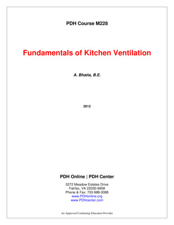
CFM of makeup air at a pressure of 2 Pa. Clearly theopening is inadequate to provide the required 800CFM of makeup air while maintaining safe pressurelevels.Even if air infiltration through the building enclosureis included in the analysis, this installation fallsshort. Interpreting Figure 4 from Part 1 of this seriesin a slightly different way, it can be determined thatinfiltration could provide about 300 CFM of makeupair while maintaining a safe pressure of 2 Pa. Addingthe makeup air from infiltration to that of theengineered opening results in a total makeup air of419 CFM. This is significantly lower than theexhaust rate of the fan; thus, the 10” opening willnot be able to maintain a safe pressure differencebetween the inside and the outside of the home.Pros of engineered openings: Relatively inexpensive.Air can be directly introduced to the space whereit is needed.Little strain on HVAC systems. Air has theopportunity to mix and temper with interior airbefore returning to central HVAC equipment.Cons of engineered openings: Additional load on central HVAC equipment.Varying degrees of effectiveness, depending onplacement of the opening.Could introduce drafts, if misplaced.Limited to lower exhaust rate applications.HVAC-INTEGRATED MAKEUP AIR SYSTEMSAnother way to add makeup air to a house is to addunconditioned outside air directly to the central airhandler. For this method, unconditioned makeup airis typically added upstream of the air handler, whereit can mix with return air and become temperedbefore reaching the central conditioning unit. Thecentral conditioning unit then filters, conditions, anddistributes makeup air throughout the house alongwith the return air.The makeup air is mechanically drawn in by the airhandler through an opening provided in theenclosure. An HVAC technician balances the flowrate of the incoming fresh air to the desired rate.When the range hood is not in operation, the openingis typically closed automatically by a motorizeddamper that is interlocked with the range hoodon/off switch. Figure 3 illustrates an example of thisconfiguration.This technique is popular for adding small quantitiesof ventilation air to houses. The central air handlerprovides adequate mixing of the fresh air with thereturn air, and evenly distributes it to all connectedrooms of the house. The even distribution of the airsupply helps to alleviate pressure imbalancesthroughout the house.Most HVAC equipment manufacturers specifyminimum and maximum return air temperatures(commonly 60 degrees F and 85 degrees F,respectively). Return air temperatures outside of thisrange may result in premature failure of heatexchangers, motors, and controls. Excessively highor low entering air temperatures will also negativelyimpact equipment efficiency. For these reasons, anHVAC designer must be careful that the rate ofmakeup air does not significantly affect thetemperature of the air entering the air handler.ACCA Manual S, Residential Equipment Selection,contains a threshold of 10 percent for the rate ofoutdoor air entering DX-type cooling equipment.Makeup air quantities of less than 10 percent ofsystem design air flow will normally notsignificantly increase risks to HVAC equipment. Forexample, if the design airflow is 1500 CFM, then itwill usually be safe to add 150 CFM ofunconditioned makeup air to the central air handler.When adding quantities of outdoor air in excess of10 percent, the entering air conditions (temperatureand relative humidity) are altered to the point wherea more detailed design should be considered.4
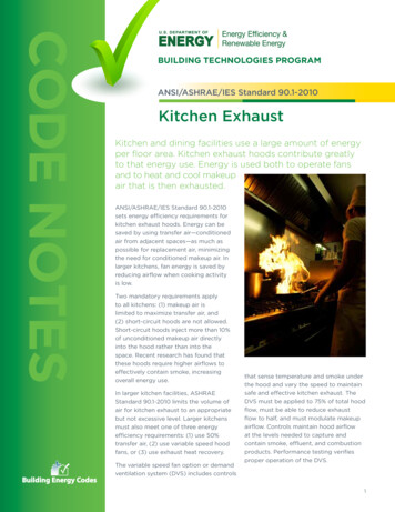
Supply airMotorized damperIntake hood equip withinsect screenReturn airFresh air into houseCentral AirHandlerDuct – Properly sized,R-8 insulation preferredVolume damperReturn air filterMixing PlenumFigure 3. Typical HVAC-integrated makeup air system. When the motorized damper is open, air enters through an opening,which is ducted to the central air handler.Finally, as with any exhaust system, heating andcooling loads will be increased commensurate withthe exhaust rate. Without additional heating andcooling capacity, occupants may experiencetemporary discomfort during, and for a brief periodafter, range hood operation. The ventilation loadscould be met by increasing the capacity of thecentral HVAC system, but it is likely that this wouldlead to equipment that is oversized for the vastmajority of its operating time.Pros of HVAC-Integrated Air Systems: Relatively inexpensive.Air is conditioned and filtered by HVAC unit.Air is evenly distributed throughout house.Cons of HVAC-Integrated Air Systems: Additional load to central HVAC equipment.Only limited quantities can be introduced to thecentral HVAC without requiring additionaldesign assistance and equipment capacity.Difficulty meeting peak heating/cooling loadswithout over-sizing central HVAC equipment.MAKEUP AIR LOADSTo illustrate the magnitude of the additional loadsfrom a 400 CFM exhaust fan, an example calculationfor a house located in State College is shown below.The calculation methodology and design conditionsare taken from ACCA Manual J.Example:Load (H) 1.1 x CFMvent x (Troom – Tvent) x ACFLoad (CS) 1.1 x CFMvent x (Tvent – Troom) x ACFLoad (CL) 0.68 x CFMvent x (GRvent – GRroom) x ACFLoad (H) Sensible Heating load (Btu/h)Load (CS) Sensible Cooling load (Btu/h)Load (CL) Latent Cooling load (Btu/h)CFMvent Ventilation rate (or makeup air rate)Troom Indoor design temperatureTvent Outdoor design temperatureACF Altitude correction factor (assume 0.97)GRvent Moisture content ventilation air (Grains)GRroom Moisture content room (Grains)Load (H) 1.1 x 400CFM x (70 – 7) x 0.97 26,888 Btu/h26,888 Btu/h x 0.293 7,878Watt-hours 7.9 kWh26,888 Btu/h /12,000 2.24 tons5
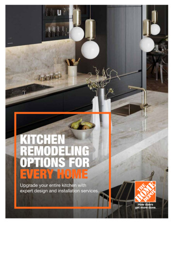
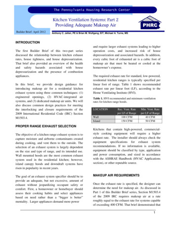
Load (CS) 1.1 x 400CFM x (87-70) x 0.97 7,256 Btu/h7,256 Btu/h x 0.293 2,126 Watt-hours 2.1 kWh7,256 Btu/h / 12,000 0.60 tonsLoad(CL) 0.68 x 400CFM x (26gr) x 0.97 6,860 Btu/h6,860 Btu/h x 0.293 2,009 Watt-hours 2.0 kWh6,860 Btu/h / 12,000 0.57 tonsSUPPLEMENTARY MAKEUP AIR CONDITIONINGEQUIPMENTIf a large amount of makeup air is required, ahomeowner will be better served by a stand-alonemakeup air conditioning system. Adding separateconditioning units will prevent overloading of thecentral HVAC unit, while allowing it to function atpeak efficiency, and eliminate any discomfort thatmight arise from introducing unconditioned air tothe living space.The example from the previous section shows thatsupplementary HVAC equipment will be helpful. Aheating unit would be desirable to condition theextra 2.24 tons of heating load, and a dehumidifierwould remove most if not all of the 0.57 tons oflatent cooling load during times of exhaustoperation. The small sensible cooling load couldmost likely be incorporated into the central HVACunit, without fear of over sizing. Figure 4 illustratesa central air handler with a makeup air heating unitand dehumidifier installed.Heating make up air can be accomplished with anyof the traditional methods of heating air (i.e.combustion equipment, DX or hot water coils, orelectric resistance coils). Particular attention must bepaid to temperature rise limitations and any adverseeffects that the entering unconditioned air mighthave on the equipment. ACCA Manuals CS, and Pare helpful references for equipment selection.One of the least design-intensive and easiest (but notalways the cheapest) ways of heating make up air isto purchase a proprietary residential makeup air unit.Supply airMotorized damperIntake hood equip withinsect screenReturn airFresh air into houseMotorized damperDehumidifierMakeup air unit orother heating unitCentral AirHandlerTemperature sensor(Optional)Duct – Properly sized,R-8 insulation preferredVolume damperMixing PlenumReturn air filterFigure 4. Typical residential makeup air unit. This installation is similar to the HVAC-integrated system, but includes adedicated heating unit and dehumidifier to temper the makeup air.6
There is a variety of companies providing theseunits, and many provide kits that include motorizeddampers, fans, and electrical interlockingcomponents. The equipment cost depends on what isincluded in the kit, with typical packages rangingfrom 1,000 to 2,500.through and open the motorized damper, allowingmakeup air to flow (Figure 5). When the fan isturned off, the circuit is closed and the signal isremoved from the damper, causing it to return to itsclosed position.ExhaustFanPros of supplementary makeup air equipment: Makeup air can usually be added to centralHVAC in greater amounts.Elimination of occupant discomfort.Easy to size and install.Minimal additional load on central HVACequipment.Neutral120 VAC230 VAC24 VX-Former115 VACNeutralCurrentSensingRelayPower PanelDamper(NC)Cons of supplementary makeup air equipment: Expensive.Additional electrical operation cost.INTERLOCKING AND CLOSUREIn order to minimize energy costs, outdoor airshould only be introduced when the kitchen exhaustsystem is in operation. IRC Section M1503.4requires that, “Makeup air systems be equipped witha means of closure and shall be automaticallycontrolled to start and operate simultaneously withthe exhaust system”.The means of closure for the three examples in thisdocument is a motorized damper. The damper isintended to prevent any outdoor air from entering thehouse when the exhaust system is not in operation.The automatic control can be accomplished with anelectrical circuit involving a current-sensing relay.Current-sensing relays are readily available fromHVAC suppliers, and are typically used as a controlelement in many humidification circuits.The current-sensing relay senses when the exhaustfan is operating. It allows a 24V signal to passFigure 5. Typical electric schematic for an exhaustsystem interlocking circuit.CONCLUSIONSMakeup air for large range hoods is important toensure occupant health and safety in any house withopen combustion equipment, or an attached garage.Negative pressures created by exhaust systems maylead to backdrafting of appliances or air infiltrationfrom hazardous sources.Designing a system to provide an adequate amountof makeup air, while maintaining occupant comfort,can be a challenge. First, a contractor or homeownershould assess whether commercial-style cookingappliances are appropriate to meet the homeowner’sneeds. If a large range and range hood are desired,the contractor must introduce sufficient makeup airto meet code and avoid potentially dangerouspressure imbalances in the house. This brief helpscontractors and installers understand the limitations,drawbacks, and benefits of three commonapproaches to providing makeup air.7
RESOURCES1. ASHRAE Handbook – Fundamentals (2009), American Society of Heating, Refrigeration and AirConditioning Engineers2. Home Ventilation Institute, www.hvi.org3. Rutkowski, Hank, Manual CS, Commercial Applications, Systems and Equipment, Air ConditioningContractors of America (ACCA)4. Rutkowski, Hank, Manual J, Residential Load Calculation, Eighth Edition, Air Conditioning Contractorsof America (ACCA)5. Rutkowski, Hank, Manual P, Psychometrics Theory and Applications, Air Conditioning Contractors ofAmerica (ACCA)6. Rutkowski, Hank, Manual S, Residential Equipment Selection, Air Conditioning Contractors of America(ACCA)Disclaimer:The Pennsylvania Housing Research Center (PHRC) exists to be of service to the housing community, especially in Pennsylvania. The PHRC conductstechnical projects—research, development, demonstration, and technology transfer—under the sponsorship and with the support of numerous agencies,associations, companies and individuals. Neither the PHRC, nor any of its sponsors, makes any warranty, expressed or implied, as to the accuracy orvalidity of the information contained in this report. Similarly, neither the PHRC, nor its sponsors, assumes any liability for the use of the information andprocedures provided in this report. Opinions, when expressed, are those of the authors and do not necessarily reflect the views of either the PHRC or anyoneof its sponsors. It would be appreciated, however, if any errors, of fact or interpretation or otherwise, could be promptly brought to our attention. Ifadditional information is required, please contact:Mike TurnsAssociate DirectorPHRCAndrew ScanlonHankin ChairPHRC8
Design considerations for makeup air systems that exceed supply rates of 400 CFM are similar to that of a commercial kitchen or industrial exhaust system. Thus, it is highly recommended that a HVAC expert be involved in the design process. Significant quantities of makeup air will increase loads placed on the central HVAC system. The