Transcription
Residential ElevatorDesign GuideAll Models - Elmira, Heritage & Cambrian1261 Industrial Rd Cambridge, ON N3H 4W3 (p) 1.800.265.3579 (p) 519.653.4222 (fl 519.653.9927www.CambridgeElevating.com
Table of ContentsIntroduction3Planning for a Cambridge Elevating Home Elevator3Provisions by Others4Description of Elevator Equipment5Hoistway Construction – General Notes6Hoistway Construction – Wood Stud Wall7Hoistway Elevation – Overhead Requirements8Pit Details9Machine Room Details – General Layout10Machine Room Details – Controller / Pump Details11Cambrian Landing Frame Details - Elevation12Cambrian Landing Frame Details - Layout13Drawings - Elmira Model Cab/Hoistway Size Layout14-15Drawings - Heritage Model Cab/Hoistway Size Layout16Drawings - Cambrian Model Cab/Hoistway Size Layout17Elevator Specifications for ASME A17.1 Part V Compliance18-21www.CambridgeElevating.comAugust 20172
IntroductionThis design guide assists architects, builders, contractors, home owners and elevator professionalsin planning for a home elevator installation that meets the requirements of ASME A17.1 Part V/CSAB44-13.Please note this guide provides nominal dimensions and specifications and is useful for initialplanning. Before starting construction please consult the specific application drawings provided byCambridge Elevating that indicate exact dimensions for your project.Please note that due to product enhancements and continually evolving codes, the information inthis guide is subject to change without notice.Planning for a Cambridge Elevating Home ElevatorThe following planning procedure is strongly recommended:1. Determine the customer’s intended use.2. Determine the customer’s desired convenience level with respect to model type: Elmira – swing landing door with manual (or automatic) accordion cab gateHeritage – swing landing door with automatic sliding cab door panelsCambrian – automatic sliding door panels on cab and each landing3. Determine local, state and national code requirements of site.4. Use pages 6 through 9 for hoistway construction, pit depth and overhead clearancerequirements.5. Use pages 10 and 11 to plan for a machine room and electrical requirements.6. Use page 12 through 15 to determine car and hoistway size requirements.7. Use page 15 and 16 to plan for the Cambrian model’s sliding landing frames.www.CambridgeElevating.comAugust 20173
Provisions By Others Provide one permanent 220/1/60 (30 amps) & one 110/1/60 (15 amps) power source to thedesignated machine room location. Both electrical disconnects are provided by the elevatormanufacturer. Provide appropriate sleeves for both the electrical conduit and hydraulic line from the drive unit tothe hoistway. Trenching may be required if the machine room is not adjacent to hoistway. Provide an enclosed, plumb and square hoistway with smooth interior surfaces, as per elevatormanufacturer's engineered drawings. Include for fascias or furring of hoistway interior. To beinspected and confirmed by elevator contractor prior to elevator installation. Provide required overhead clearance based on engineered drawings. Provide floor finishes inside elevator cab. Suitable lintels over landing entrances are to be provided for Cambrian model only – per CambrianLanding Frame Details, see page 12. Provide required rough openings at each hoistway landing as per elevator manufacturer'sengineered drawings. Provide sufficient machine-room area suitable to contain hydraulic power unit and elevatorcontroller & disconnect based on elevator manufacturer's engineered drawings. Provide telephone connection to outside line for integration into elevator controller. Provide required pit depth and size as per elevator manufacturer's engineered drawings. Provide substantial level pit floor slab to support loads indicated on elevator manufacturer'sengineered drawings. Provide required structural support for guide rail fastenings as per elevator manufacturer'sengineered drawings. Install rail bracket inserts (Supplied by CE) into concrete rail support wall during construction perelevator manufacturer's engineered drawings, only if required. Provide required building permit(s) and/or engineering services as per local authorities. Provide pit water proofing or sump pump, only if required. Provide all finishes around landing door frames and landing entrances.www.CambridgeElevating.comAugust 20174
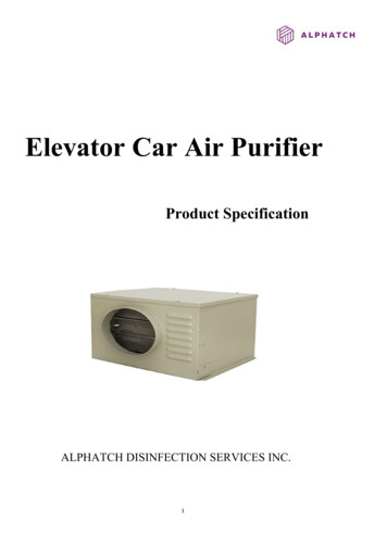
Description of Elevator EquipmentGeneral Rated load: Up to 1,500 lbs. where permittedby local codes Nominal speed: 40 feet per minute Elmira minimum pit depth: 8” Elmira minimum overhead clearance: 96” Heritage/Cambrian minimum pit depth: 12” Heritage/Cambrian minimum overhead: 108” Maximum travel: 50 feet Maximum number of stops: 6Controls Microprocessor controller with relays for basicoperation Fully automatic operation Automatic timed cab lighting Stainless steel car operating panel (COP),telephone box and hall call stations Dual illuminated hall call station push buttonsand position indicating push buttons on COP Emergency stop switch on COP LED/dot matrix Digital Position Indicator (DPI)in carMechanical Equipment 220 VAC, 60 Hz, 30 Amp single phase power Dual 8 lb. modular T-rail system Two 3/8” diameter, 17 x 9 wire ropes Sling assembly Forged rope sockets 2:1 roped hydraulic single stage cylinder Submersed electric motor with 2-speedadjustable valve systemSafety Devices Stainless steel handrail inside cab 220 VAC lockable disconnect for power unit Final limit switch Slack rope safety switch Pit stop switch Car top stop switch Line rupture valve Low pressure switch Automatic leveling (anti-creep) Emergency battery lowering Electro-mechanical door interlocks Manual lowering device Telephone in cabCab and Appointments Car size: Up to 20 sq. ft. standard Cab height: 84" standard, 96" & custom optional Recessed LED cab lights – 2 or 4 lights dependingon cab size Interior cab walls and ceiling finish, choice of:Melamine: cherry, oak, maple, walnut, white, blackVeneer (unfinished) –birch, cherry, maple, oak,walnut(MDF) Medium density fibreboard – paint grade Rough plywood cab floor with ¾” recessOptions Custom cab sizes/heights. Oversized cabswhere permitted (variance may be required) Unfinished oak, maple or cherry solidhardwood / face frame hardwood cab walls andceiling Stainless steel patterned cab walls and ceilingGates and Doors Elmira Custom finish elevator fixtures (COP, telephoneSwing door for each landingbox and hall call stations) in choice of platingHorizontally collapsible accordion style car gate(s)finishes: Brushed brass, oil rubbed bronze, Heritagepolished stainless, brushed nickel, consultSwing door for each landingfactory for additional choices.Automatic sliding cab door panels (beige or s/s) Two piece hydraulic jack Cambrian Additional handrails in cabAutomatic sliding cab door panels (beige or s/s) Handrail COP (all models)Automatic sliding landing door panels (beige or s/s) LED/dot matrix Digital Position Indicator (DPI)hall call stations on landings Veneer and decorative metal wrapped slidingdoor panels t 20175
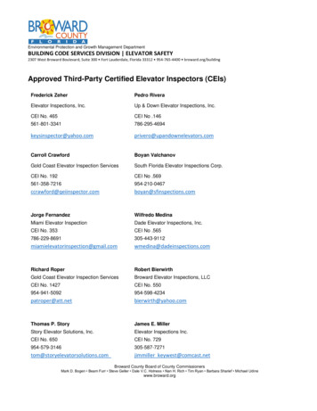
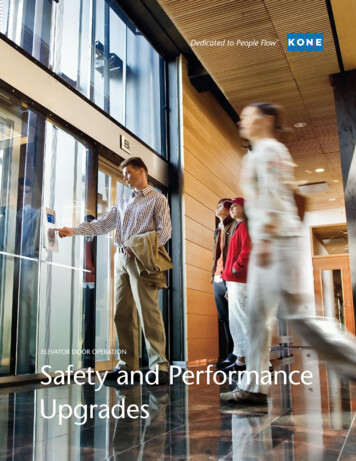
Hoistway Construction – General Notes A load-bearing wall is required to sustain rail reactions; please see Rail Wall Construction – Wood StudWall (next page) for detail. Hoistway must be in accordance with ASME A17.1/CSA B44-13, AND all local codes and regulations. Pit floor construction must withstand a 5,500 lb. load. Due to limited clearances, it is necessary that hoistway walls be square and plumb. Maximumpermissible deviation from hoistway top to bottom is 1/8”. Building structure must sustain a chain hoist for hoisting elevator materials to the top of the hoistwayduring installation. A structural engineer must ensure that building and hoistway can safely support all loads imposed bythe elevator equipment. The drawings contained herein have been prepared using engineering principles and the designloads that are applied by the rails to the wall. However the details and member sizes and theattachments to the structure should not be construed as a complete wall system. The contractorand/or the project engineer are responsible to evaluate the other loads that are applied to the wallfrom the floor or roof system and modify sizes or connections as required by their analysis.www.CambridgeElevating.comAugust 20176
RAIL WALL SHEATHING3/4" PLYWOODSCREWED TO STUDS EVERY 12"WITH #10-2-1/2" SCREWS MINIMUM2"X4"FOR BEST RESULTS USE A CONSTRUCTIONADHESIVE IN ADDITION TO REQUIREDWOOD SCREWSWALLS WITH DOOROPENINGS MUST HAVE2"X4" CONSTRUCTIONALL OTHER WALLSAS PER LOCALBUILDING CODESURFACE OF PLYWOODFLUSH WITH WALL OF PITPITBOTTOM FLOORSLABRAIL CENTERLINEAS PER PROJECTSHOP DRAWINGSMIDDLE STUDSTHREE 2" x 6"116 4 "116 4 "- CHANNEL CONSTRUCTION TYPICALTWO PLACES- TWO 2" x 12" INSIDE TWO 2" x 6"- 2x6s SCREWED TO 2x12s EVERY 6"WITH#10x3-1/2" WOOD SCREWS- CHANNELS AND MIDDLE STUDSBETWEEN FLOORS FULL HEIGHT OFHOISTWAYR3 720LBSRAIL WALL CHANNELASSEMBLYTOP VIEWDOORWALLR1 720LBSR2 225LBS3/4"PLYWOODCAMBRIDGE ELEVATING IS NOTRESPONSIBLE FOR THE STRUCTURALDESIGN OF THE BUILDING AND ITSABILITY TO SUPPORT THE ELEVATORLOADS AND/OR REACTIONSTHIS DRAWING AND THE INFORMATION IT CONTAINS ARE PROPRIETARY TOCAMBRIDGE ELEVATING INC. THIS DOCUMENT MUST NOT BE DUPLICATED,OR ITS CONTENTS USED OR DISCLOSED (IN WHOLE OR IN PART) WITHOUTTHE WRITTEN PERMISSION FROM CAMBRIDGE ELEVATING INC.1261 INDUSTRIAL RDCAMBRIDGE, ONTARIOWWW.CAMBRIDGEELEVATING.COM
FINISH BASEMENT8" MIN ELMIRA12" FOR HERITAGE OR CAMBRIANSECTION A-A4.0" MINIMUMAS PER HOISTWAY LAYOUTPIT FLOOR TO BE MADE OFMINIMUM 15MPa CONCRETEAAAS PER HOISTWAY LAYOUTPIT FLOOR TO BE DESIGNED FOR AN IMPACT LOAD OF 9600LBSAND A STATIC LOAD OF 5500LBS UNDER CYLINDERREINFORCING AND STRENGTH AS PER LOCALSTANDARDS AND CODESTHIS DRAWING AND THE INFORMATION IT CONTAINS ARE PROPRIETARY TOCAMBRIDGE ELEVATING INC. THIS DOCUMENT MUST NOT BE DUPLICATED,OR ITS CONTENTS USED OR DISCLOSED (IN WHOLE OR IN PART) WITHOUTTHE WRITTEN PERMISSION FROM CAMBRIDGE ELEVATING INC.RESIDENTIAL PIT DETAILS1261 INDUSTRIAL RDCAMBRIDGE, ONTARIOWWW.CAMBRIDGEELEVATING.COM
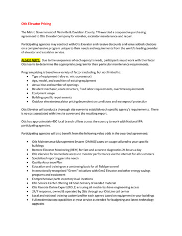
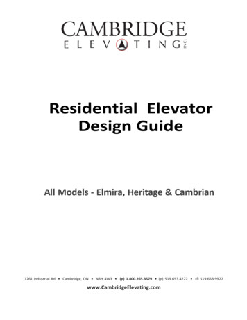
Machine Room Details – General Layout Machine room must be in accordance with all codes and regulations. A 220 VAC, 60 Hz, 30 Amp single phase power source in the machine room to be provided. A 115 VAC, 60 Hz, 15 Amp single phase power source in the machine room to be provided. A telephone line circuit to be provided if required. This circuit must be connected to an outsideline.August 2017www.CambridgeElevating.com10
16 2 " MIN CLEARANCE329 4 "SHUT OFFVALVEHYDRAULIC LINE TOCYLINDER1310 4 " 12 4 " 14"128 4 "FILLER BREATHERFOR OILTO BE LOCATED WITHIN 20ft OFELEVATOR HOISTWAYFOR LONGER DISTANCES CONSULTCAMBRIDGE ELEVATING3.0 or 5.0 H.P. 220V/1/60Hz DRIVE MOTORACCESS REQUIRED TO TOP OF UNITFOR OIL FILLING AND PIPINGDISCONNECTS SUPPLIED BY C.E.I. ONMAIN ELEVATOR CONTROL PANEL32"HYDRAULIC OIL: 32 WEIGHT PREMIUMCAPACITY: 75L / 20 US Ga126 4 "MAIN ELEVATORCONTROLLER PANEL126 4 "PLYWOOD28"WIRE GAUGE ASPER LOCAL CODEREQUIREMENTS30"LIGHTINGDISCONNECT120VAC15 AMPNEMA 5-15PPLUGPUMPDISCONNECT240VAC30 AMPNEMA 14-30PPLUG182"128 4 "HYDRAULICPOWER UNITOUTLETS TO BESUPPLIED BY G.CWITHIN 36" OF THECONTROLLER ON THERIGHT SIDE.REQUIRES:* NEMA 5-15OUTLET AT 60" HIGH* NEMA 14-30OUTLET AT 48" HIGHUSUALLY MOUNTED INMECHANICAL ROOMON WALL WITHIN 6' OFHYDRAULIC POWER UNITOR TO STRUTS MOUNTEDON REAR OF PUMP TANKBES3 RESIDENTIAL PUMPCONTROLLER DETAILS13"THIS DRAWING AND THE INFORMATION IT CONTAINS ARE PROPRIETARY TOCAMBRIDGE ELEVATING INC. THIS DOCUMENT MUST NOT BE DUPLICATED,OR ITS CONTENTS USED OR DISCLOSED (IN WHOLE OR IN PART) WITHOUTTHE WRITTEN PERMISSION FROM CAMBRIDGE ELEVATING INC.1261 INDUSTRIAL RDCAMBRIDGE, ONTARIOWWW.CAMBRIDGEELEVATING.COM
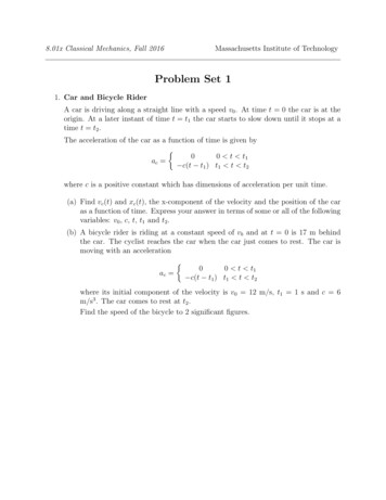
Cambrian Landing Frame Details – Elevation It is the recommendation of Cambridge Elevating to leave door walls wide open for installation. Landing door jambs and header fit within rough stud opening. Landing door operating mechanism,door frames and sill hang in hoistway attached to inside wall of hoistway using brackets. Drawing below depicts view from landing looking into elevator hoistway (rails support on right wall).www.CambridgeElevating.comAugust 201712
Cambrian Landing Frame Details – Layout It is the recommendation of Cambridge Elevating to leave door walls wide open for installation.www.CambridgeElevating.comAugust 201713
Elmira Model Cab / Hoistway Size LayoutCab SizeHoistway SizeWidth x DepthCenterlinesRailLandingWallDoor36” x 48”54” x 54.25”31”26.75”36” x 54”54” x 60.25”31”28.25”36” x 60”54” x 66.25”31”31.25”40” x 48”58” x 54.25”35”26.75”40” x 54”58” x 60.25”35”28.25”Please note dimensions remain for mirrored configurations.TYPE 1 – INLINECab SizeHoistway Size36” x 48”Width x Depth54” x 36” x 54”54” x 56.5”31”27.25”36” x 60”54” x 62.5”31”31.25”40” x 48”58” x 50.5”35”24.25”40” x 54”58” x 56.5”35”27.25”Please note dimensions remain for mirrored configurations.TYPE 2 – THROUGHwww.CambridgeElevating.comAugust 201714
Elmira Model Cab / Hoistway Size LayoutCab SizeHoistway SizeCenterlinesLandingRailDoorWallWidth x Depth44” x 42”54” x 56.25”31”27”48” x 42”58” x 56.25”35”29”54” x 48”64” x 62.25”41”32”60” x 48”70” x 62.25”47”35”Please note dimensions remain for mirrored configurations.TYPE 5 – INLINECab SizeHoistway SizeWidth x DepthCenterlinesRailLandingWallDoor36” x 48”51.75” x 54.25”28.5”25.25”40” x 60”55.75” x 66.25”33”31.25”48” x 48”63.75” x 54.25”40.5”25.25”48” x 60”63.75” x 66.25”40.5”31.25”Please note dimensions remain for mirrored configurations.TYPE 3 or 4 (90-DEGREE) LH or RHwww.CambridgeElevating.comAugust 201715
Heritage Model Cab / Hoistway Size LayoutCab SizeHoistway SizeWidth x Depth44” x 48”62” x 57.75”(2 panel ��36” x 48”(3 panel doors)54” x 56.875”32.75”28.0625”36” x 60”(3 panel doors)54” x 70.5”32.75”34.0625”40” x 54”(3 panel doors)58” x 62.5”34.75”31.0625”Please note dimensions remain for mirrored configurations.TYPE 1 – INLINECab SizeHoistway SizeWidth x Depth44” x 48”62” x 58.5”(2 panel doors)36" x 48”54” x 59.75”(3 panel doors)36" x 60”(3 panel doors) 54” x 71.75”40" x 54"(3 panel doors)58” x 75”Please note dimensions remain for mirrored configurations.TYPE 2 – THROUGHwww.CambridgeElevating.comAugust 201716
Cambrian Model Cab / Hoistway Size LayoutCab SizeHoistway SizeWidth x Depth44” x 48”62” x 61.75”(2 panel ��36” x 48”(3 panel doors)54” x 63.25”32.75”33”36” x 60”(3 panel doors)54” x 75.25”32.75”39”40” x 54”(3 panel doors)58” x 69.25”34.75”36”Please note dimensions remain for mirrored configurations.TYPE 1 – INLINECab SizeHoistway SizeWidth x Depth44” x 48”62” x 65.75”(2 panel ��36" x 48”(3 panel doors)54” x 68.5”32.75”34.25”36" x 60”(3 panel doors)54” x 80.5”32.75”40.25”40" x 54"(3 panel doors)58” x 74.5”34.75”37.25”Please note dimensions remain for mirrored configurations.TYPE 2 – THROUGHwww.CambridgeElevating.comAugust 201717
Cambridge Elevating Inc. Residential Elevator SpecificationsPART 1 – GENERAL1.1 SummaryThis specification describes the planning, labor, and materials required to install a private residence homeelevator manufactured by Cambridge Elevating Inc.1.2 System DescriptionA private residence 1:2 roped hydraulic elevator complete with guide rail system, hydraulic power unit,control panel, switches, wiring and any parts necessary to properly install the elevator to meetperformance, safety and code standards.1.3 Quality AssuranceThe elevator shall be designed, tested and installed in compliance with all applicable regulations and inaccordance with ASME A17.1/CSA B44.0 standards. Elevator may be subject to state, local and city approvalprior to installation and subject to inspection after installation.1.4 Applicable Codes and Standards1.4.11.4.21.4.31.4.41.4.5ASME A17.1/CSA B44-13, Section 5.3 Private Residence ElevatorsASME A17.5/CSA B44.1, Elevator and Escalator Electrical EquipmentICC/ANSI A117.1-1998, Accessible and Usable Buildings and FacilitiesNFPA 70-1999, National Electric CodeADAAG, Americans with Disabilities Act Accessibility GuidelinesPART 2 – PREPARATORY WORK BY OTHERS2.1 HoistwayProvide an enclosed, plumb and square hoistway with smooth interior surfaces. Provide fascias or furringof hoistway interior where required. Provide correct door RSO and headers as described on site specificlayout drawings. Construction of hoistway, including rail support wall and pit floor must withstand all loadsas described on site specific layout drawings. Rail wall construction must provide adequate anchoringmeans for guide rail support system as described in hoistway detail drawings.2.2 Machine RoomProvide a machine room as required by applicable codes and standards.2.3 Electrical2.3.1 General Contractor to provide one 220 VAC, 60 Hz, 30 Amp single phase power source in the machineroom. 230 VAC disconnect provided by Cambridge Elevating.2.3.2 General Contractor to provide one 120VAC, 60 Hz, 15 Amp power source and disconnect in themachine room. 120 VAC disconnect provided by Cambridge Elevating.www.CambridgeElevating.comAugust 201718
PART 3 – SUBMITALS3.1 Approval DrawingsApproval drawings shall show a complete layout of elevator equipment, including plan and elevationviews.PART 4 – PRODUCT4.1 Equipment ManufacturerThe elevator shall be manufactured by Cambridge Elevating Inc.4.2 ComponentsThe elevator will have the following components.4.2.1 Cab4.2.1.1 Car sizes (please visit our full drawings pages at (http://cambridgeelevating.com/tools)Please refer to the Drawings pages for representative standard sizes. Custom cab sizes are available,please consult your authorized dealer or CE sales representative.** A minimum cab width of 44” is required for 2-speed/panel doors.4.2.1.2 Cab ConfigurationInline (enter/exit same side), 90 degree or straight-thru layouts available.4.2.1.3 Cab ConstructionMetal bracket and/or tubular frame structure with melamine, veneer, stainless steel or laminate finishpanels. Ceiling white melamine or to match walls. Rough plywood floor is supplied - finish flooring byothers.4.2.1.4 Car Operating PanelA brushed stainless steel flush panel is built into the cab wall. Floor selection pushbuttons with a dual colorLED floor number and annular ring. Alarm button, emergency stop button, emergency light and integralphone box with phone and hinged cover are included.www.CambridgeElevating.comAugust 201719
4.2.1.5 Hand RailBrushed stainless steel handrail mounted to cab wall (shipped loose in unfinished cabs) in solid flat bar orcylindrical. (Standard handrail is 36” x 1½” straight ends, flat)4.2.2 Hydraulic Power Unit and MotorPower unit to consist of 20 U.S. gallon enclosed metal tank, 4.0hp or 5.0hp submersible induction motorand pump. Two-speed valve complete with adjustable leveling, pressure relief valve and shut off ball valve.Pressure gauge, manual lowering valve and overheat thermistor included. Tank heater option is available.4.2.3 ControllerCertified relay controller utilizing a Machine Control Unit (MCU) to manage the flow of signal information.Battery back-up to allow lowering of car and unlocking and opening of doors during power outages.4.2.4 CylinderSingle stage jack with line rupture valve, 750 psi working pressure.4.2.5 RopesTwo 3/8” diameter, 9 x 17 wire ropes.4.2.6 Guide railDual 8 lb. steel modular T-rail system.4.2.7 Car SlingThe elevator cab shall be supported by the car sling. The car sling shall be made of structural and formedsteel and equipped with guide rollers and Type "A" roller safeties complete with slack rope safety switch.4.2.8 Gates and DoorsLandings: Automatic horizontally sliding two or three speed side opening beige epoxy or brushed stainlessdoor panels complete with matching frame and sill OR Manual swing door on landing provided by GeneralContractor, the electromechanical door interlock can be provided by CEI (Automatic door operatoravailable).Cab Door/Gate: Automatic horizontally sliding two or three speed side opening beige epoxy or brushedstainless panels complete with sill OR horizontally sliding collapsible accordion style car gate (variousfinishes available).www.CambridgeElevating.comAugust 201720
4.2.9 Safety DevicesThe elevator will have the following safety devices:4.2.9.1 208/230 VAC lockable disconnect for power unit4.2.9.2 Final limit4.2.9.3 Slack rope safety switch4.2.9.4 Pit stop switch4.2.9.5 Car top stop switch4.2.9.6 Line rupture valve4.2.9.7 Low pressure switch4.2.9.8 Automatic re-leveling4.2.9.9 Emergency battery lowering4.2.9.10 Electro-mechanical door interlocks4.2.9.11 Manual lowering device4.2.9.12 Handrail inside cab4.2.9.13 Emergency lighting in cab4.2.9.14 Phone in cabPART 5 – EXECUTION5.1 ExaminationAll site dimensions and conditions shall be verified to ensure they meet specifications, codes andregulations.5.2 InstallationConfirm that all site dimensions and conditions match those specified on shop drawings. Do not proceedwith installation if the site dimensions and conditions are not acceptable. Elevator shall be installed bytrained technicians in accordance with approved plans, specifications, manufacturer’s installationinstructions and local codes.5.3 MaintenanceElevator shall be maintained in accordance with the manufacturer’s instructions and all applicable codes.5.4 WarrantyElevator shall carry a thirty-six (36) month limited warranty on parts only.www.CambridgeElevating.comAugust 201721
A structural engineer must ensure that building and hoistway can safely support all loads imposed by the elevator equipment. The drawings contained herein have been prepared using engineering principles and the design loads that are applied by the rails