Transcription
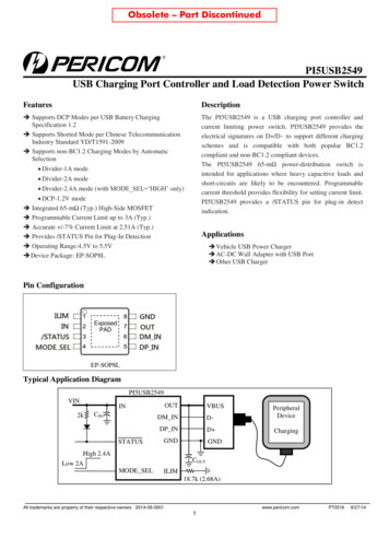
Obsolete – Part DiscontinuedPI5USB2549USB Charging Port Controller and Load Detection Power Switch FeaturesDescription Supports DCP Modes per USB Battery ChargingSpecification 1.2 Supports Shorted Mode per Chinese TelecommunicationIndustry Standard YD/T1591-2009 Supports non-BC1.2 Charging Modes by AutomaticSelectionThe PI5USB2549 is a USB charging port controller andcurrent limiting power switch. PI5USB2549 provides theelectrical signatures on D /D– to support different chargingschemes and is compatible with both popular BC1.2compliant and non-BC1.2 compliant devices.The PI5USB2549 65-mΩ power-distribution switch isintended for applications where heavy capacitive loads andshort-circuits are likely to be encountered. Programmablecurrent threshold provides flexibility for setting current limit.PI5USB2549 provides a /STATUS pin for plug-in detectindication. Divider-1A mode Divider-2A mode Divider-2.4A mode (with MODE SEL ’HIGH’ only) DCP-1.2V mode Integrated 65-mΩ (Typ.) High-Side MOSFET Programmable Current Limit up to 3A (Typ.) Accurate /-7% Current Limit at 2.51A (Typ.) Provides /STATUS Pin for Plug-In Detection Operating Range:4.5V to 5.5V Device Package: EP-SOP8LApplications Vehicle USB Power Charger AC-DC Wall Adapter with USB Port Other USB ChargerPin ConfigurationExposedPADEP-SOP8LTypical Application DiagramPI5USB2549VINOUTIN2kCINSTATUSVBUSDM IND-PeripheralDeviceDP IND ChargingGNDGNDHigh 2.4ACOUTLow 2AMODE SELILIM18.7k (2.68A)All trademarks are property of their respective owners 2014-08-0001www.pericom.com1PT05168/27/14
PI5USB2549USB Charging Port Controller and Load Detection Power Switch Pin DescriptionPin #NameTypeDescription1ILIMI2INP3STATUSO4MODE SELI5DP INI/O6DM INI/O7OUTPPower-switch output8GNDGGround connectionExposed PADGGround connection.External resistor connection used to set the current-limit threshold.Input voltage and supply voltage; connect 0.1μF//10μF or greater ceramic capacitorfrom IN to GND as close to the device as possibleActive-low open-drain output as a plug-in detect indication. It is asserted when thereis a load connected.Logic-level input signal used to control the Divider-2.4A charging mode.MODE SEL ’HIGH’ enables Divider-2.4A charging mode. MODE SEL ’LOW’disables Divider-2.4A charging mode.Connected to the D line of USB connector, provide the correct voltage with attachedportable equipment for DCP detection.Connected to the D- line of USB connector, provide the correct voltage with attachedportable equipment for DCP detection.* I Input; O Output; P Power; G GroundPI5USB2549 Charging Detection Supports TablePart NumberPI5USB2549Non- BC1.2 Charging nDetection MODE SELLOWHIGHAll trademarks are property of their respective owners 2014-08-0001www.pericom.com2PT05168/27/14
PI5USB2549USB Charging Port Controller and Load Detection Power Switch Maximum RatingsAll Input (except IN to OUT, and DP IN, DM IN).-0.3V to 6.0VIN to OUT .-6.0V to 6.0VDP IN, DM IN . -0.3V to IN 0.3 or 5.7VInput clamp current (DP IN, DM IN). 20mAContinuous current in BC1.2 DCP mode (DP IN to DM IN) . 50mAContinuous output current (OUT).Internally limitedContinuous output sink current (/STATUS).25mAContinuous output source current (ILIM).internally limitedESD: HBM Mode (All pins) .2kVCDM Mode (All pins). 500VHBM (USB connector pins: DP IN, DM IN, OUT to GND).6kVNote:Stresses greater than those listed under MAXIMUMRATINGS may cause permanent damage to the device.This is a stress rating only and functional operation of thedevice at these or any other conditions above thoseindicated in the operational sections of this specificationis not implied. Exposure to absolute maximum ratingconditions for extended periods may affect reliability.Recommended Operating nput Voltage, logic-level MODE SEL input0-5.5VVDP INDP IN data line voltage0-VINVVDM INDM IN data line voltage0-VINVInput Voltage, INVINVIHHigh-level input voltage, MODE SEL1.8--VVILLow-level input voltage, MODE SEL--0.8VContinuous output current, OUT0-2.5AContinuous output sink current, /STATUS0-10mACurrent-limit set resistor16.9-750kΩTAAmbient Temperature Range-40-85ºCTJOperating Virtual Junction Temperature Range-40-125ºCIOUTRILIMAll trademarks are property of their respective owners 2014-08-0001www.pericom.com3PT05168/27/14
PI5USB2549USB Charging Port Controller and Load Detection Power Switch Electrical Characteristics4.5V VIN 5.5V; TJ -40 C to 125 C; R/STATUS 10kΩ RILIM 20kΩPositive currents are into pins. Typical values are at 25 C. All voltages are with respect to GND. unless otherwise specified.SymbolParameterTest ConditionsMinTyp.MaxUnitTJ 25oC, IOUT 2A-65--40oC TJ 85oC, IOUT 2A-65105-40oC TJ 125oC, IOUT V--200-mV-0.5-0.5µAPower SwitchRDS(on)On Resistance(1)mΩDischargeRDCHGOUT discharge resistanceVOUT 4VtDCHGOUT discharge hold timeTime VOUT 0.7VMODE SEL inputInput pin rising logicthreshold voltageInput pin falling logicthreshold voltageHysteresis(2)Input currentPin voltage 0V to 5.5V(1) Pulse-testing techniques maintain junction temperature close to ambient temperature; Thermal effects must be taken into account separately(2) These parameters are provided for reference only and do not constitute part of Pericom's published device specifications for purposes of Pericom's productwarrantyAll trademarks are property of their respective owners 2014-08-0001www.pericom.com4PT05168/27/14
PI5USB2549USB Charging Port Controller and Load Detection Power Switch Electrical Characteristics4.5V VIN 5.5V; TJ -40 C to 125 C; R/STATUS 10kΩ RILIM 20kΩPositive currents are into pins. Typical values are at 25 C. All voltages are with respect to GND. unless otherwise specified.SymbolDescriptionTest 227525102970275680243026853170mA-1.5- s-215270 AILIM Current LimitIOSOUT Current-limit(2)RILIM 210kΩRILIM 80.6kΩRILIM 22.1kΩRILIM 20kΩVIN RILIM 16.9kΩtIOSResponse time to OUT short circuit(1)VIN 5.0V, R 0.1Ω, lead length 2”Supply CurrentIIN ONIN supply currentUndervoltage LockoutVUVLOIN rising UVLO threshold utput low voltageI/STATUS 1mA--100mVIOFFOff-state leakageV/STATUS 5.5V--1 A170-20-Thermal ShutdownOTSDThermal shutdown threshold-(1)Hysteresis-- CNote:(1) These parameters are provided for reference only and do not constitute part of Pericom's published device specifications for purposes of Pericom's productwarranty(2) Pulse-testing techniques maintain junction temperature close to ambient temperature; current limit value tested at 80% output voltage. Thermal effects must betaken into account separately.All trademarks are property of their respective owners 2014-08-0001www.pericom.com5PT05168/27/14
PI5USB2549USB Charging Port Controller and Load Detection Power Switch Electrical Characteristics, Charging Controller4.5V VIN 5.5V; TJ -40 C to 125 C; R/STATUS 10kΩ RILIM 20kΩPositive currents are into pins. Typical values are at 25 C. All voltages are with respect to GND. unless otherwise specified.SymbolDescriptionTest P IN Divider-1A output voltage1.92.02.1VDM IN Divider-1A output voltage2.572.72.84VDP IN/DM IN output n detect set time140200275msPlug-in detect reset time1.934.2sSHORTED MODE (BC1.2 DCP)DP IN/DM IN shorting resistanceDCP-1.2V MODEDP IN/DM IN output voltageDP IN/DM IN output impedanceApply 3V on DP IN for 0.5s andmeasure the D /D- voltage within the 2sDIVIDER-1A MODEDIVIDER-2A MODEDP IN Divider-2A output voltageDM IN Divider-2A output voltageIOUT 1ADP IN/DM IN output impedanceDIVIDER-2.4A MODE (with MODE SEL ’HIGH’)DP IN/DM IN output voltageDP IN/DM IN output impedanceIOUT 2APLUG-IN LOAD DETECTIPLUG INTPLUG INIPLUG IN rising set current thresholdIPLUG IN falling reset currentthresholdSETNote:(1) These parameters are provided for reference only and do not constitute part of Pericom's published device specifications for purposes ofPericom's product warranty.All trademarks are property of their respective owners 2014-08-0001www.pericom.com6PT05168/27/14
PI5USB2549USB Charging Port Controller and Load Detection Power Switch Functional DescriptionPI5USB2549 Block DiagramINOUTUVLO PumpOCUVLOGNDOTSDThermalSenseDriverDM INDP E SELAll trademarks are property of their respective owners 2014-08-0001www.pericom.com7PT05168/27/14
PI5USB2549USB Charging Port Controller and Load Detection Power Switch OverviewThe following overview references various industry standards. It is always recommended to consult the most up-to-datestandard to ensure the most recent and accurate information. Rechargeable portable equipment requires an external powersource to charge its batteries. USB ports are a convenient location for charging because of an available 5V power source.Universally accepted standards are required to make sure host and client-side devices operate together in a system to ensurepower management requirements are met. Traditionally, host ports following the USB 2.0 specification must provide at least500mA to downstream client-side devices. Because multiple USB devices can be attached to a single USB port through a buspowered hub, it is the responsibility of the client-side device to negotiate its power allotment from the host to ensure the totalcurrent draw does not exceed 500mA. In general, each USB device is granted 100mA and may request more current in 100mAunit steps up to 500mA. The host may grant or deny based on the available current. A USB 3.0 host port not only provideshigher data rate than USB 2.0 port but also raises the unit load from 100mA to 150mA. It is also required to provide a minimumcurrent of 900mA to downstream client-side devices.Additionally, the success of USB has made the mini-USB connector a popular choice for wall adapter cables. This allows aportable device to charge from both a wall adapter and USB port with only one connector. As USB charging has gainedpopularity, the 500mA minimum defined by USB 2.0 or 900mA for USB 3.0 has become insufficient for many handset andpersonal media players which need a higher charging rate. Wall adapters can provide much more current than 500mA/900mA.Several new standards have been introduced defining protocol handshaking methods that allow host and client devices toacknowledge and draw additional current beyond the 500mA/900mA minimum defined by USB 2.0/3.0 while still using asingle micro-USB input connector. The PI5USB2549 supports four of the most common USB charging schemes found inpopular hand-held media and cellular devices: USB Battery Charging Specification BC1.2Chinese Telecommunications Industry Standard YD/T 1591-2009Divider-1A, Divider-2A and Divider-2.4A ModeDCP-1.2V ModeYD/T 1591-2009 is a subset of BC1.2 spec. supported by vast majority of devices that implement USB charging.Divider-1A, Divider-2A, Divider-2.4A and DCP-1.2V charging schemes are supported in devices from specific yet populardevice makers.All trademarks are property of their respective owners 2014-08-0001www.pericom.com8PT05168/27/14
PI5USB2549USB Charging Port Controller and Load Detection Power Switch DCP Auto ModePI5USB2549 integrates an auto-detect state machine that supports all the below DCP charging schemes. It starts in Divider-1Ascheme, however if a BC1.2 or YD/T 1591-2009 compliant device is attached, the PI5USB2549 responds by discharging OUT,turning back on the power switch and operating in 1.2Vmode briefly and then moving to BC1.2 DCP mode. It then stays in thatmode until the device is done charging or removed, in which case it goes back to Divider-1A scheme. When a Divider-1Acompliant device is attached the PI5USB2549 will stay in Divider-1A state.Also, the PI5USB2549 will automatically switch between the Divider-1A and Divider-2A (or Divider-2.4A) schemes based oncharging current drawn by the connected device. Initially the device will set the DP IN/DM IN to Divider-1A scheme. Ifcharging current of the device 900mA is measured by the PI5USB2549, it switches to Divider-2A scheme and test to see if theperipheral device will still charge at a high current. With MODE SEL ’HIGH’, if charging current of the device 1.8A ismeasured by PI5USB2549 or PI5USB2549, it will switches to Divider-2.4A charging mode. If it does then it stays in Divider2A or Divider-2.4A charging scheme otherwise it will revert to Divider-1A scheme.PI5USB2549DDCP AutoBC1.2 DCP/DCP-1.2VD Divider-1A/2A /2.4AFigure 1, DCP Auto ModeDCP BC1.2 and YD/T 1591-2009Both standards define that the D and D- data lines should be shorted together with a maximum series impedance of 200Ω.This is shown as Figure .2V2.7VD GNDFigure 2, DCP modeAll trademarks are property of their respective owners 2014-08-0001www.pericom.com9PT05168/27/14
PI5USB2549USB Charging Port Controller and Load Detection Power Switch Divider-1A, Divider-2A and Divider-2.4A Charging SchemeThere is two charging mode supported by PI5USB2549 with MODE SEL pin LOW or HIGH. PI5USB2549 supports to flagDivider-1A/Divider-2A/Divider-2.4A charging scheme as MODE SEL pin pulls to IN (HIGH), and if MODE SEL pin pulls toGND (LOW), the device supports to flag Divider-1A/Divider-2A charging scheme. In Divider-1A charging scheme the deviceapplies 2.0V and 2.7V to D and D- data line respectively. This is reversed in Divider-2A mode. Divider-2.4A chargingscheme on PI5USB2549 is applying 2.7V on both D and D-. The Divider-1A, Divider-2A and Divider-2.4A scheme are asshown 2V2.0VD GNDFigure 3a, Divider-1A Charging Scheme (with MODE SEL or1.2V2.7VD GNDFigure 3b, Divider-2A Charging Scheme (with MODE SEL or1.2V2.7VD GNDFigure 3c, Divider-2.4A Charging Scheme (with MODE SEL “HIGH”)All trademarks are property of their respective owners 2014-08-0001www.pericom.com10PT05168/27/14
PI5USB2549USB Charging Port Controller and Load Detection Power Switch DCP-1.2V Charging SchemeDCP-1.2V charging scheme is used by some handheld devices to enable fast charging at 2.0A. PI5USB2549 supports thisscheme in the DCP-Auto mode before the device enters BC1.2 shorted mode. To simulate this charging scheme D /D- lines areshorted and pulled-up to 1.2V for fixed duration then device moves to DCP shorted mode as defined in BC1.2 spec. This isshown as Figure 7VD GNDFigure 4, DCP-1.2V Charging SchemeOutput DischargeTo allow a charging port to renegotiate current with a portable device, PI5USB2549 uses the OUT discharge function. Itproceeds by turning off the power switch while discharging OUT, then turning back on the power switch to reassert the OUTvoltage.Over-Current ProtectionWhen an over-current condition is detected, the device maintains a constant output current and reduces the output voltageaccordingly. Two possible overload conditions can occur. In the first condition, the output has been shorted before the device isenabled or before VIN has been applied. The PI5USB2549 senses the short and immediately switches into a constant-currentoutput. In the second condition, a short or an overload occurs while the device is enabled. At the instant the overload occurs,high currents may flow for nominally one to two microseconds before the current-limit circuit can react. The device operates inconstant-current mode after the current-limit circuit has responded. Complete shutdown occurs only if the fault is presentedlong enough to activate thermal limiting. The device will remain off until the junction temperature cools approximately 20 Cand will then re-start. The device will continue to cycle on/off until the over-current condition is removed.All trademarks are property of their respective owners 2014-08-0001www.pericom.com11PT05168/27/14
PI5USB2549USB Charging Port Controller and Load Detection Power Switch Current-Limit SettingThe PI5USB2549 has an independent current limit setting that is programmed externally with a resistor. The ILIM setting isprogrammed with RILIM connected between ILIM and GND.The following equation programs the typical current limit:IOS TYP (mA) 50250/RLIM (kΩ)Many applications require that the current limit meet specific tolerance limits. When designing to these tolerance limits, boththe tolerance of the PI5USB2549 current limit and the tolerance of the external programming resistor must be taken intoaccount. The following equations approximate the PI5USB2549 minimum / maximum current limits to within a few mA andare appropriate for design purposes. These equations assume an ideal – no variation - external programming resistor. To takeresistor tolerance into account, first determine the minimum /maximum resistor values based on its tolerance specifications anduse these values in the equations. Because of the inverse relation between the current limit and the programming resistor, usethe maximum resistor value in the IOS MIN equation and the minimum resistor value in the IOS MAX equation.IOS MIN (mA) 45271/(RLIM (kΩ))0.98437-30IOS MAX (mA) 55325/ (RLIM (kΩ)) 1.0139 30The traces routing the RILIMI resistor should be a sufficiently low resistance as to not affect the current-limit accuracy. Theground connection for the RILIM resistor is also very important. The resistors need to reference back to the PI5USB2549 GNDpin. Follow normal board layout practices to ensure that current flow from other parts of the board does not impact the groundpotential between the resistors and the PI5USB2549 GND pin.Undervoltage Lockout (UVLO)The undervoltage lockout (UVLO) circuit disables the power switch until the input voltage reaches the UVLO turn on threshold.Built-in hysteresis prevents unwanted oscillations on the output due to input voltage drop from large current surges.Thermal SenseThe PI5USB2549 protects itself with thermal sensing circuit that monitor the operating temperature of the power distributionswitch and disables operation if the temperature exceeds recommended operating conditions. The device operates in constantcurrent mode during an over-current condition, which increases the voltage drop across power switch. The power dissipation inthe package is proportional to the voltage drop across the power switch, so the junction temperature rises during an over-currentcondition. The thermal sensor turns off the power switch when the die temperature exceeds 135 C regardless of whether thepower switch is in current limit. Hysteresis is built into thermal sensor, and the switch turns on after the device has cooled byapproximately 20 C. The switch continues to cycle off and on until the fault is removed.Application InformationInput and Output CapacitanceInput and output capacitance improves the performance of the device; the actual capacitance should be optimized for the particularapplication. For all applications, a 0.1uF or greater ceramic bypass capacitor between IN and GND is recommended as close to thedevice as possible for local noise decoupling. This precaution reduces ringing on the input due to power-supply transients.Additional input capacitance 10uF or greater may be needed on the input to reduce voltage overshoot from exceeding the absolutemaximum voltage of the device during heavy transient conditions or output shorting. Normally suggested the distance between ICand DC supply is less than 15cm.Output capacitance also needs to be close to IC as possible. When large transient currents are expected on the output, placing ahigh-value low ESR electrolytic capacitor 100uF or greater on the output pin is recommended.All trademarks are property of their respective owners 2014-08-0001www.pericom.com12PT05168/27/14
PI5USB2549USB Charging Port Controller and Load Detection Power Switch Mechanical InformationEP-SOP8LOrdering InformationPart No.PI5USB2549WAEPackage CodeWAPackageLead free and Green 8-pin EP-SOPNote: E Pb-free and Green Adding X Suffix Tape/ReelPericom Semiconductor Corporation 1-800-435-2336 www.pericom.comPericom reserves the right to make changes to its products or specifications at any time, without notice, in order to improve design or performance and to supplythe best possible product. Pericom does not assume any responsibility for use of any circuitry described other than the circuitry embodied in Pericom product. Thecompany makes no representations that circuitry described herein is free from patent infringement or other rights, of Pericom.All trademarks are property of their respective owners 2014-08-0001www.pericom.com13PT05168/27/14
7 OUT P Power-switch output 8 GND G Ground connection Exposed PAD G Ground connection. * I Input; O Output; P Power; G Ground . PI5USB2549 Charging Detection Supports Table . Part Number MODE_SEL Non- BC1.2 Charging Mode Plug-in DCP-1.2V Divider-1A Divider-2A Divider-2.4A Detection . PI5USB2549 LOW . . HIGH