Transcription
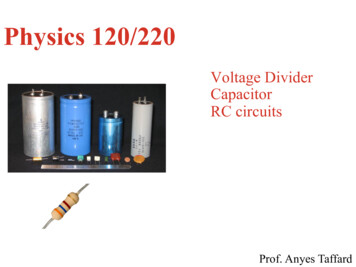
Physics 120/220Voltage DividerCapacitorRC circuitsProf. Anyes Taffard
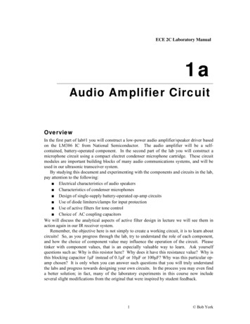
Voltage Divider2The figure is called a voltage divider.It’s one of the most useful and important circuit elements we willencounter.It is used to generate a particular voltage for a large fixed Vin.Current (R1 & R2) I VinR1 R2Output voltage:Vout IR2 R2VinR1 R2 Vout VinVoltage drop isproportional to theresistancesVout can be used to drive a circuit that needs a voltage lower than Vin.
Voltage Divider (cont.)3Add load resistor RL in parallel to R2.You can model R2 and RL as one resistor (parallel combination), thencalculate Vout for this new voltage dividerIf RL R2, then the output voltage is still:R2VL VinR1 R2However, if RL is comparable to R2, VL is reduced. We say that thecircuit is “loaded”.
Ideal voltage and current sourcesVoltage source: provides fixed Vout regardless of current/load resistance.Has zero internal resistance (perfect battery).Real voltage source supplies only finite max I.Current source: provides fixed Iout regardless of voltage/load resistance.Has infinite resistance.Real current source have limit on voltage they can provide.Voltage source More common In almost every circuit Battery or Power Supply (PS)4
Thevenin’s theorem5Thevenin’s theorem states that any two terminals network of R & V sources hasan equivalent circuit consisting of a single voltage source VTH and a single resistorRTH.To find the Thevenin’s equivalent VTH & RTH: For an “open circuit” (RLà ), thenVTh Vopen circuit Voltage drops across device when disconnected from circuit – no external loadattached. For a “short circuit” (RLà0), thenRTh Vopen circuitI short circuit I short circuit current when the output is shorted directly to the ground.
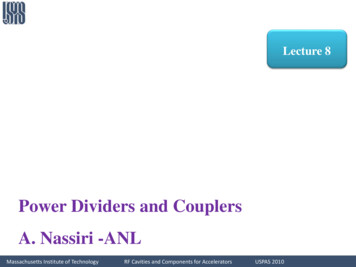
Thevenin’s theorem (cont)6TheveninequivalentOpen circuit voltage:Short circuit current:R2VTH Vout VinR R2Vin 1I short circuit R1Lower leg of dividerTotal RThevenin equivalent:Voltage source: VTH Vin R2R1 R2in series with:RTH R1R2R1 R2V open-circuit – no external load“like” R1 in parallel with R2RTh is called the output impedance (Zout) of the voltage divider
Thevenin’s theorem (cont)Very useful concept, especially when different circuits are connectedwith each other. Closely related to the concepts of input and outputimpedance (or resistance).Circuit A, consisting of VTH and RTH, is fed to the second circuitelement B, which consists of a simple load resistance RL.7
Avoiding circuit loadingThe combined equivalent circuit (A B) forms avoltage divider:RVVout VTHLRTH RL (R R )TH1 THLRTH determines to what extent the output of the1st circuit behave as an ideal voltage source.To approximate ideal behavior and avoid loading the circuit, the ratio RTH/RLshould be kept small.10X rule of thumb: RTH/RL 1/10The output impedance of circuit A is the Thevenin equivalent resistance RTH(also called source impedance).The input impedance of circuit B is its resistance to ground from the circuitinput. In this case, it is simply RL.8
Example: voltage dividerVin 30V, R1 R2 Rload 10ka) Output voltage w/ no load [Answ 15V]b) Output voltage w/ 10k load [Answ 10V]9
Example (cont.)c) Thevenin equivalent circuit [VTH 15V, RTH 5k]d) Same as b) but using the Thevenin equivalent circuit [Answ 10V]e) Power dissipated in each of the resistor [Answ PR1 0.04W, PR2 PRL 0.01W]10
Example: impedance of a VoltmeterWe want to measure the internal impedance of a voltmeter.Suppose that we are measuring Vout of the voltage divider: RTH: 2 100k in parallel, 100k/2 50k VTH 20 Measure voltage across Rin (Vout) 8V, thus 2V drop across RTH100k 10V2 100k The relative size of the two resistances are in proportion of these two voltagedrops, so Rin must be 4 (8/2) RTH , so Rin 200k11
12Terminology
Terminology (cont)13Offset biasA DC voltage shifts an AC voltage up or down.DC biasAC signalAC signal with DC offsetGain:AV VoutVinVoltage gainI outAI I inUnity gain: Vout VinCurrent gain
Terminology14When dealing with AC circuits we’ll talk about V & I vs time or Avs f.Lower case symbols: i: AC portion of current waveform v: AC portion of voltage waveform. V(t) VDC vDecibels:amplitude 2To compare ratio of two signals: dB 20 log10amplitude 1Often used for gain: eg ratio is 1.4 220 log10 1.4 3 dBNB: 3dB power ratio of ½ amplitude ratio of 0.7
15Capacitors and RCcircuits
Capacitor: reminder16Q CVconducting platesQ: total charge [Coulomb]insulatorC: capacitance [Farad 1F 1C/1V]C QA ε0[parallel-plate capacitor]VdV: voltage across capSincedQI dtI CdVdtI: rate at which charge flowsor rate of change of the voltageFor a capacitor, no DC current flows through, but AC current does.Large capacitances take longer to charge/discharge than smaller ones.Typically, capacitances are µF (10-6) pF (10-12)Ceq C1 C2 C3 [parallel]Same voltage drop across caps1111 Ceq C1 C2 C3All caps have same Q[series]
Frequency analysis of reactive circuitI(t) CV (t) V0 sin(ω t)dV (t) Cω V0 cos(ω t)dtie the current is out of phase by 90o to wrtvoltage (leading phase)Considering the amplitude only: I V01ωCω 2π f1Frequency dependent resistance: R 1ω C 2π fCExample: C 1µFI rms 110V (rms)1101(2π 60 10 ) 660Hz power line 41.5mA(rms)I rms I217
Impedance of a capacitorImpedance is a generalized resistance.It allows rewriting law for capacitors so that it resembles Ohm’s law.Symbol is Z and is the ratio of voltage/current.dVRecall: I CdtdI CV0 e jω t jω CV0 e jω tdtV0 e jω tI jωC(V (t) V0 cos(ω t) Re V0 e jω t ) V0 e jω t The actual current is: I Re Z c Zc j ω CZc is the impedance of a capacitor at frequency ω.As ω (or f) increases (decreases), Zc decreases (increases)The fact that Zc is complex and negative is related to the fact the the voltage acrossthe cap lags the current through it by 90o.18
Ohm’s law generalized19V (t) ZI(t)Ohm’s law for impedances:V! Z!I!using complex notationZ eq Z1 Z 2 Z3 [series]1111 Z eq Z1 Z 2 Z3[parallel]Resistor:ZR Rin phase with ICapacitor:Z c j ω C 1 jω CZ L jω Llags I by 90oInductor:leads I by 90o(use mainly in RF circuits)Can use Kirchhoff’s law as before but with complex representation of V & I.Generalized voltage divider:V!out V!inZ! 2Z!1 Z! 2
RC circuit20Capacitor is uncharged. At t 0, the RC circuit is connected to the battery (DC voltage)The voltage across the capacitor increases with time according to:I CdV Vi V dtRàV Vi Ae tRCA is determined by the initial condition:@ t 0, V 0 thus A -Vi(V Vi 1 e tRC)when t RC 1/e 0.37VViRate of charge/discharge is@ 1RC 63% of voltagedetermined by RC constant@ 5RC 99% of voltageTime constant RC:For R Ohms and C in Farads, RC is in secondsFor MΩ and µF, RC is secondsFor kΩ and µF, RC is ms0.63Vi
RC circuit (cont.)21Consider a circuit with a charge capacitor, a resistor, and a switchVτ RC time constantVi0.37ViBefore switch is closed, V Vi and Q Qi CViAfter switch is closed, capacitor discharges and voltage acrosscapacitor decreases exponentially with timedVVC I dtRàV Vi e t/RC
Differentiator22Consider the series RC circuit as a voltage divider, with the output correspondingto the voltage across the resistor:V across C is Vin-VdVI C (Vin V ) dtRIf we choose R & C small enough so thatdVdV indtdtdV(t) RCVin (t)then,dtThus the output differentiate the input waveform!Simple rule of thumb: differentiator works well ifVout VinDifferentiators are handy for detecting leading edges & trailing edges in pulsesignals.
Integrator23Now flip the order of the resistor and capacitor, with the output corresponding tothe voltage across the capacitor:V across R is Vin-VI CdV Vin V dtRIf RC is large, then V Vin andCdV Vin dtRtà1V (t) Vin (t)dt cst RCThus the output integrate the input!Simple rule of thumb: integrator works well ifVout VinIntegrators are used extensively in analog computation (eg analog/digitalconversion, waveform generation etc )
High-pass filter24Let’s interpret the differentiator RC circuit as a frequency-dependent voltagedivider (“frequency domain”):j ! Using complex Ohm’s law:Voltage across R is: V!out( )( )V!in R j ω C ! R IRR2 1 2 2ω CIf we care only about the amplitude: ( )Vin R ω C!! VVininI! 2Z! total R jR 1 2 2ω CωCVout(* V!outV!outVoltage divider made of R & C)12 Vin R 1 2 2 ω C 12Thus Vout increases with increasing fImpedance of a series RC combination: Z! total R jRωCjZ2 1 ωCφ tan R 1RϕZ total R 2 1-j/ωCNote phase ofoutput signalω 2C 2Vout VinRZ totalimpedance oflower-leg of dividerMagnitude ofimpedance of R & C
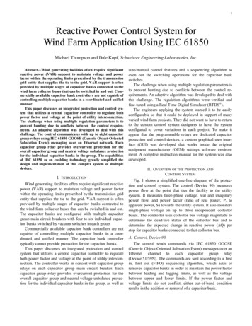
High-pass filter frequency response3dB below unitOutput equal to input at high frequencywhen ω 1/RC [rad]Goes to zero at low frequency.High-pass filter frequency response curveA high-pass filter circuit attenuates low frequency and “passes” the highfrequencies.The frequency at which the filter “turns the corner” (ie Vout/Vin 1/ 2 0.7) iscalled the 3dB point:f3dBoccurs when Zc R1 [Hz]2π RC25Use this in labotherwise factor 2π offNB: 3dB power ratio of ½ amplitude ratio of 0.7
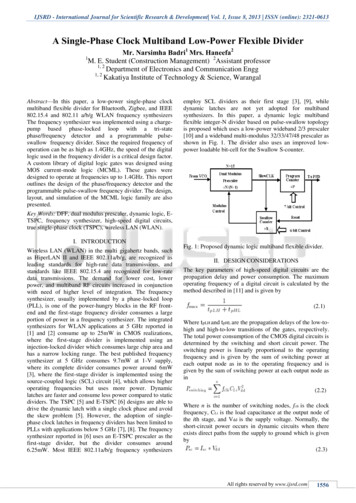
Low-pass filter26Now simply switch the order of the resistor and capacitor in the series circuit(same order as the integrator circuit earlier):impedance ofVout Vin1ωC R2 1 2 2 ω C lower-leg of divider12Magnitude ofimpedance of R & CA low-pass filter circuit attenuates high frequency and “passes” the low frequencies.3dB below unitLow-pass filter frequency response curve
Voltage Divider 2 The figure is called a voltage divider. It's one of the most useful and important circuit elements we will encounter. It is used to generate a particular voltage for a large fixed V in. Current (R 1 & R 2) Output voltage: V out can be used to drive a circuit that needs a voltage lower than V in. I V in R 1 R 2 V out IR 2 R .